EP0208077A1 - Procédé et dispositif de perforation de feuilles d'empaquetage pour aliments - Google Patents
Procédé et dispositif de perforation de feuilles d'empaquetage pour aliments Download PDFInfo
- Publication number
- EP0208077A1 EP0208077A1 EP86105988A EP86105988A EP0208077A1 EP 0208077 A1 EP0208077 A1 EP 0208077A1 EP 86105988 A EP86105988 A EP 86105988A EP 86105988 A EP86105988 A EP 86105988A EP 0208077 A1 EP0208077 A1 EP 0208077A1
- Authority
- EP
- European Patent Office
- Prior art keywords
- roll
- film
- perforating
- rolls
- blades
- Prior art date
- Legal status (The legal status is an assumption and is not a legal conclusion. Google has not performed a legal analysis and makes no representation as to the accuracy of the status listed.)
- Withdrawn
Links
- 235000013305 food Nutrition 0.000 title claims abstract description 29
- 238000000034 method Methods 0.000 title claims description 23
- 230000002093 peripheral effect Effects 0.000 claims abstract description 9
- 238000005520 cutting process Methods 0.000 claims description 23
- 235000013372 meat Nutrition 0.000 description 5
- 238000004519 manufacturing process Methods 0.000 description 4
- 235000013622 meat product Nutrition 0.000 description 4
- 238000004806 packaging method and process Methods 0.000 description 4
- 235000013580 sausages Nutrition 0.000 description 4
- 239000000463 material Substances 0.000 description 3
- 238000013022 venting Methods 0.000 description 3
- 229920000297 Rayon Polymers 0.000 description 2
- 239000000839 emulsion Substances 0.000 description 2
- 239000012530 fluid Substances 0.000 description 2
- 235000021178 picnic Nutrition 0.000 description 2
- 229920000642 polymer Polymers 0.000 description 2
- 238000012545 processing Methods 0.000 description 2
- 238000009738 saturating Methods 0.000 description 2
- 238000002791 soaking Methods 0.000 description 2
- 239000007787 solid Substances 0.000 description 2
- JOYRKODLDBILNP-UHFFFAOYSA-N Ethyl urethane Chemical compound CCOC(N)=O JOYRKODLDBILNP-UHFFFAOYSA-N 0.000 description 1
- 241000288147 Meleagris gallopavo Species 0.000 description 1
- 230000015572 biosynthetic process Effects 0.000 description 1
- 230000001112 coagulating effect Effects 0.000 description 1
- 238000007796 conventional method Methods 0.000 description 1
- 238000013461 design Methods 0.000 description 1
- 230000003028 elevating effect Effects 0.000 description 1
- 239000003925 fat Substances 0.000 description 1
- 239000002657 fibrous material Substances 0.000 description 1
- 235000011389 fruit/vegetable juice Nutrition 0.000 description 1
- 239000000499 gel Substances 0.000 description 1
- 235000015110 jellies Nutrition 0.000 description 1
- 239000008274 jelly Substances 0.000 description 1
- 239000011159 matrix material Substances 0.000 description 1
- 238000012986 modification Methods 0.000 description 1
- 230000004048 modification Effects 0.000 description 1
- 229920006280 packaging film Polymers 0.000 description 1
- 239000012785 packaging film Substances 0.000 description 1
- 238000012856 packing Methods 0.000 description 1
- 230000000149 penetrating effect Effects 0.000 description 1
- 239000004800 polyvinyl chloride Substances 0.000 description 1
- 229920000915 polyvinyl chloride Polymers 0.000 description 1
- 244000144977 poultry Species 0.000 description 1
- 235000013594 poultry meat Nutrition 0.000 description 1
- 235000013613 poultry product Nutrition 0.000 description 1
- 238000002360 preparation method Methods 0.000 description 1
- 229920002994 synthetic fiber Polymers 0.000 description 1
- 239000012815 thermoplastic material Substances 0.000 description 1
- 238000012546 transfer Methods 0.000 description 1
- XLYOFNOQVPJJNP-UHFFFAOYSA-N water Substances O XLYOFNOQVPJJNP-UHFFFAOYSA-N 0.000 description 1
Images


Classifications
-
- B—PERFORMING OPERATIONS; TRANSPORTING
- B26—HAND CUTTING TOOLS; CUTTING; SEVERING
- B26F—PERFORATING; PUNCHING; CUTTING-OUT; STAMPING-OUT; SEVERING BY MEANS OTHER THAN CUTTING
- B26F1/00—Perforating; Punching; Cutting-out; Stamping-out; Apparatus therefor
- B26F1/18—Perforating by slitting, i.e. forming cuts closed at their ends without removal of material
- B26F1/20—Perforating by slitting, i.e. forming cuts closed at their ends without removal of material with tools carried by a rotating drum or similar support
-
- B—PERFORMING OPERATIONS; TRANSPORTING
- B26—HAND CUTTING TOOLS; CUTTING; SEVERING
- B26D—CUTTING; DETAILS COMMON TO MACHINES FOR PERFORATING, PUNCHING, CUTTING-OUT, STAMPING-OUT OR SEVERING
- B26D5/00—Arrangements for operating and controlling machines or devices for cutting, cutting-out, stamping-out, punching, perforating, or severing by means other than cutting
- B26D5/08—Means for actuating the cutting member to effect the cut
-
- B—PERFORMING OPERATIONS; TRANSPORTING
- B26—HAND CUTTING TOOLS; CUTTING; SEVERING
- B26D—CUTTING; DETAILS COMMON TO MACHINES FOR PERFORATING, PUNCHING, CUTTING-OUT, STAMPING-OUT OR SEVERING
- B26D5/00—Arrangements for operating and controlling machines or devices for cutting, cutting-out, stamping-out, punching, perforating, or severing by means other than cutting
- B26D5/20—Arrangements for operating and controlling machines or devices for cutting, cutting-out, stamping-out, punching, perforating, or severing by means other than cutting with interrelated action between the cutting member and work feed
- B26D5/22—Arrangements for operating and controlling machines or devices for cutting, cutting-out, stamping-out, punching, perforating, or severing by means other than cutting with interrelated action between the cutting member and work feed having the cutting member and work feed mechanically connected
-
- Y—GENERAL TAGGING OF NEW TECHNOLOGICAL DEVELOPMENTS; GENERAL TAGGING OF CROSS-SECTIONAL TECHNOLOGIES SPANNING OVER SEVERAL SECTIONS OF THE IPC; TECHNICAL SUBJECTS COVERED BY FORMER USPC CROSS-REFERENCE ART COLLECTIONS [XRACs] AND DIGESTS
- Y10—TECHNICAL SUBJECTS COVERED BY FORMER USPC
- Y10T—TECHNICAL SUBJECTS COVERED BY FORMER US CLASSIFICATION
- Y10T83/00—Cutting
- Y10T83/04—Processes
- Y10T83/0515—During movement of work past flying cutter
-
- Y—GENERAL TAGGING OF NEW TECHNOLOGICAL DEVELOPMENTS; GENERAL TAGGING OF CROSS-SECTIONAL TECHNOLOGIES SPANNING OVER SEVERAL SECTIONS OF THE IPC; TECHNICAL SUBJECTS COVERED BY FORMER USPC CROSS-REFERENCE ART COLLECTIONS [XRACs] AND DIGESTS
- Y10—TECHNICAL SUBJECTS COVERED BY FORMER USPC
- Y10T—TECHNICAL SUBJECTS COVERED BY FORMER US CLASSIFICATION
- Y10T83/00—Cutting
- Y10T83/465—Cutting motion of tool has component in direction of moving work
- Y10T83/4728—Tool flies by engagement with the work
-
- Y—GENERAL TAGGING OF NEW TECHNOLOGICAL DEVELOPMENTS; GENERAL TAGGING OF CROSS-SECTIONAL TECHNOLOGIES SPANNING OVER SEVERAL SECTIONS OF THE IPC; TECHNICAL SUBJECTS COVERED BY FORMER USPC CROSS-REFERENCE ART COLLECTIONS [XRACs] AND DIGESTS
- Y10—TECHNICAL SUBJECTS COVERED BY FORMER USPC
- Y10T—TECHNICAL SUBJECTS COVERED BY FORMER US CLASSIFICATION
- Y10T83/00—Cutting
- Y10T83/465—Cutting motion of tool has component in direction of moving work
- Y10T83/4766—Orbital motion of cutting blade
- Y10T83/4795—Rotary tool
- Y10T83/4818—Interconnected work feeder and tool driver
-
- Y—GENERAL TAGGING OF NEW TECHNOLOGICAL DEVELOPMENTS; GENERAL TAGGING OF CROSS-SECTIONAL TECHNOLOGIES SPANNING OVER SEVERAL SECTIONS OF THE IPC; TECHNICAL SUBJECTS COVERED BY FORMER USPC CROSS-REFERENCE ART COLLECTIONS [XRACs] AND DIGESTS
- Y10—TECHNICAL SUBJECTS COVERED BY FORMER USPC
- Y10T—TECHNICAL SUBJECTS COVERED BY FORMER US CLASSIFICATION
- Y10T83/00—Cutting
- Y10T83/929—Tool or tool with support
- Y10T83/9314—Pointed perforators
-
- Y—GENERAL TAGGING OF NEW TECHNOLOGICAL DEVELOPMENTS; GENERAL TAGGING OF CROSS-SECTIONAL TECHNOLOGIES SPANNING OVER SEVERAL SECTIONS OF THE IPC; TECHNICAL SUBJECTS COVERED BY FORMER USPC CROSS-REFERENCE ART COLLECTIONS [XRACs] AND DIGESTS
- Y10—TECHNICAL SUBJECTS COVERED BY FORMER USPC
- Y10T—TECHNICAL SUBJECTS COVERED BY FORMER US CLASSIFICATION
- Y10T83/00—Cutting
- Y10T83/929—Tool or tool with support
- Y10T83/9372—Rotatable type
- Y10T83/9408—Spaced cut forming tool
Definitions
- the present invention relates to films used in packaging food products, and more particularly, to methods and apparatus for making perforated tubular food casings used in processing and packaging meat and sausage products.
- fibrous reinforced films are prepared by saturating a paper or other tubular web with a continuous matrix of a film forming polymer, like viscose which is then regenerated, washed, plasticized and dried.
- fibrous food casings are frequently prestuck by perforating with either multiple needle or circular punch size holes which allow venting of the casing during stuffing operations.
- perforations provide for shorter stuffing cycles since air can be more readily discharged through the casing sidewall. The perforations also operate to enhance and facilitate drainage of any water, fat or jelly pockets which might otherwise form during or after processing of the meat product.
- the size and shape of the perforations can be critical.
- food casings having vent holes which are either undersized, flared or have frayed edges experience statistically higher failure rates from rupturing during stuffing. Offsetting this ⁇ problem usually means slower stuffing cycles due to extended venting times.
- poor drainage can occur with undersized perforations leading to unappetizing fatty-gel deposits developing between the outer surface of the product and the inner sidewall of the casing. Similar undesirable results can also arise when perforations are oversized, in which case meat emulsion and desirable natural juices can be lost from the package.
- prestuck food casing films can be prepared with greater control over-the dimensions of perforations using the improved methods and apparatus of the present invention.
- the casing/workpiece being pulled through the apparatus provides the mechanical energy for operating the device to perforate the film with multiple small punctures, slits, etc.
- the perforations are formed by a rotatable perforating roll having multiple knife blades, etc., linked to and driven by a rotatable drive roll which turns the perforating roll at the same or substantially the same velocity as the drive roll.
- the apparatus is actuated by engaging the perforating roll and the drive roll with the film and advancing the film causing the drive roll to rotate and the blades to perforate the film.
- the perforating blades, etc., radially projecting from the surface of the perforating roll cooperate with a backup roll so as to enter a complimentary arrangement of slits or voids in the backup roll after perforating the-casing so the blades avoid making contact with the backup roll, thereby providing more efficient means for perforating the film and for cleaner, more uniform perforations which means, tubular film with greater reliability, as well as extended life expectancy of the blades, etc., and backup roll.
- a further aspect of the invention includes the use of multiple spaced knife blades radially mounted on the perforating roll.
- the blades preferably have a slanted or beveled cutting edge at their outermost terminal ends where the farthest extending point of each blade edge making contact with the film provides a piercing action followed by a slitting action as the balance of the blade edge penetrates through the film as the perforating roll turns.
- the slanted cutting edge minimizes flared, frayed or uneven perforations, as well as oversized perforations.
- FIG. 1 there is seen a finished prestuck film 10 made according to the present invention.
- the prestuck films 10 are nonedible, fibrous materials which have been formed by saturating a paper web or other cellulosic or noncellulosic manufactured fiber, etc., with viscose or other film forming polymer, which is usually regenerated in a coagulating bath, washed, -plasticized and dried before presticking operations.
- prestuck film 10 is illustrated in the form of flattened tubular material 12 the present invention also contemplates preparation of perforated materials as flat ribbon films prior to being seamed into tubular casing.
- the methods and apparatus described herein may be used in preparing nonfibrous, unreinforced food films they are especially desirable in preparing reinforced packaging films for heavier whole, chunk style and large size sausage and meat products, like whole hams, picnics and poultry products, including poultry parts, turkey rolls, deli loaves, bolognas and whenever strong, large size food casings are indicated.
- food casing films which are premoisturized and in ready-to-stuff condition with sufficient moisture content that additional soaking prior to stuffing can be eliminated before being used by food processors.
- prestuck food films moisturized by meat processors and premoisturized food casings moistened by casing manufacturers having multiple rows of perforations 14 preferably have a plurality of slits 16 rather than conventional pin or punch style holes where, for instance, perforations are formed by removing small pieces of casing film. It was found that the longitudinal slits are especially effective in venting air from the moistened casing with statistically fewer failures due to rupturing during filling operations. Shorter, more efficient stuffing cycles are achieved with slits ranging in length from about 1 mm to about 6 mm running parallel to the longitudinal axis of the film.
- the longer slits are most adaptable for casings used in packaging whole meat products like hams, whereas slits of shorter length are more suitable for stuffing meat emulsions for sausage products.
- the slits are introduced into the film with the apparatus described herein equipped with multiple knife blades described in greater detail below.
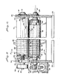
- FIG. 2 illustrates presticker apparatus 20 of the present invention for making perforated casings whereby the leading end of a flattened tubular film 18 is pulled through the apparatus, for example, by a collecting reel (not shown) located downstream of the apparatus.
- the apparatus includes a support base 22 and outer frame members 24 and 25 having an access opening 95'.
- the tubular film 18 is initially threaded between a pair of guide rolls 26 and 28 supported by bracket 34 and guide roll shafts 30 and 32.
- FIG. 3 best illustrates a first set of rotatable rolls comprising an upper perforating roll 36 and a lower backup roll 42.
- the perforating roll is equipped with multiple perforating members 102 selected from spaced knife blades, punches, piercing needles, etc., projecting radially from the surface of the roll.
- Rolls 36 and 42 cooperate to form a nip therebetween in which the film 75 is drawn.
- FIG. 4 illustrates a second set of rotatable rolls comprising an upper power roll 74 and lower squeeze roll 78.
- Rolls 74 and 78 cooperate to form a nipping surface therebetween for passage of film 75:
- the second set of rolls 74 and 78 are parallel to and aligned with the first set of rolls 36 and 42.
- the first and second sets of rolls are linked together such that advancement of film 75 through their respective nipping surfaces engages power roll 74 causing it to rotate and simultaneously turn perforating roll 36.
- film guides 21 and.23 (FIG. 2) are employed.
- a center film guide 66 (FIG. 2) positioned between the first and second sets of rolls may also be used.
- Guide rolls 27 and 29 (FIG. 2) positioned at the exiting end of the apparatus directing perforated film to the collection reel (not shown) are supported by bracket 35 and guide roll shafts 31 and 33.
- perforating roll 36 is mounted on shaft 44 between frame members 24 and 25. Shaft 44 and roll 36 are mounted for rotation on bearings 90 and supported by frame members 24 and 25, the shaft and roll turning when end pulley 40 keyed to slot 46 (FIG. 2) is rotated by drive belt.48 extending from power roll 74.
- the perforating roll 36 is preferably an assembly of separate holders 96 shaped in the form of annular discs of uniform dimension compressed into a unitary structure between nut 88 secured by threads 92 on shaft 44 (FIG. 3) and shaft shoulder 88' (Fig. 6).
- Perforating roll 36 is driven by power roll 74 with the objective that the peripheral speed of the power roll and the rotating perforating members 102 radially extending from the surface of roll 36 will be the same or substantially the same. Accordingly, the workpiece 18 passing between the nips of the first and second sets of rolls provides the mechanical energy for the apparatus turning the power roll 74 which drives the perforating roll and perforating members through the film. In other words, the peripheral speed of the rotating perforating members and the linear speed of the compressed casing 93 (Fig. 4) passing between the rolls will be equal or virtually the same.
- Power roll 74 like perforating roll 36 is mounted on a shaft 70 between frame members 24 and 25.
- Roll 74 drives shaft 70 through set screw 98 keyed to slot 100, rotating on bearings 71 when compressed casing 93 is advanced through the nip created by the roll 74 and lower squeeze roll 78.
- the rotation of shaft 70 also turns pulley 68 (FIG. 2) keyed through slot 72.
- drive belt 48 is shown as one means for transferring energy from power roll 74 to the perforating roll 36 it is understood that alternative means may be used, for instance, gears, including idlers in place of pulleys and drive belts to transfer energy to the perforating roll, so that the peripheral speed of the perforating roll will be equivalent to the linear speed of the workpiece passing between the rolls.
- FIG. 3 also illustrates comb 95 in the form of a bar running parallel to the rolls positioned above film 75 and downstream to roll 36.
- Comb 95 retains the film in a flattened condition as roll 36 turns and perforating members 102 are withdrawn from the film.
- Roll 42 (FIG. 3) serves as a backup to perforating roll 36 engaging tubular films 75 at the nip formed between said rolls compressing the film and providing a support surface for the film while the. perforating members 102 pass through both surfaces of the flatten tubular material.
- Backup roll 42 is equipped with terminal bearings 55 at each end of the roll which roll is mounted for rotation about shaft 50, the latter of which includes eccentric terminal stub shafts 76.
- Roll 42 and shaft 50 are pivotally mounted through their eccentric stub shafts 76 which pass through frame members 24 and 25 and rotate on bearings 54.
- the surface of backup roll 42 which may be polyvinyl chloride or other suitable thermoplastic material has a series of relatively narrow parallel slots or voids 97 for receiving the perforating members 102 protruding from the surface of roll 36.
- the dimensions of slots 97 should be at least equal to the length and width of the perforating members entering the slots so as to avoid making contact with the backup roll. This will also extend the serviceable life expectancy of the knives, punches or needlelike elements used in perforating the film and the rolls before replacement becomes necessary. With the apparatus of the present invention cutting. blades, punches, needles, etc., make contact only with workpiece 75, and therefore, the perforations are formed.with greater efficiency and without tearing or fraying the film in the process.
- Squeeze roll 78 (FIG. 4) operates with power roll 74 compressing film 93 as it is pulled through the apparatus.
- Roll 78 preferably may have outer urethane layer 104 to aid in frictional engagement of the rolls as the film advances through the apparatus.
- Squeeze roll 78 like backup roll 42, has terminal bearings 87 for rotation of the roll about a central shaft 81, the shaft including eccentric terminal stub shafts 67.
- Roll 78 and shaft 81 are pivotally mounted through eccentric stub shafts 67 which pass through frame members 24 and 25 and rotate on bearings 82.
- FIG. 2 illustrates the lower rolls in nipping engagement with the flattened film.
- rolls 42 and 78 may be lowered by turning their eccentric shafts 76 and 67. This may be performed by connecting terminal stub shafts 76 and 67 to disengaging and re-engaging means which generally include eccentric arms 60 and 80 (FIG. 2) and motor means 89 therefor.
- Eccentric arm 80 includes an upper arm 61, an extension of clamp 79, which grips eccentric terminal stub shaft 67 with the aid of locking bolt 83.
- the upper arm 61 is interconnected to eccentric arm 60 by tanged link 62 through linking pins 64 and 69 at narrowed sections 65 and 73.
- Eccentric arm 80 including a lower arm extension 59 is connected to rod 85 of fluid cylinder 84 through linking pin 52.
- Cylinder 84 such as a pneumatic or hydraulic fluid powered cylinder of conventional design may be used. Actuation of the cylinder is controlled through valve 86.
- perforating roll 36 includes a plurality of film perforating members 102 extending radially from the surface of the roll.
- the perforating members may include any film penetrating element, such as punches, needles, blades and the like.
- the present invention preferably utilizes a plurality of spaced knife blades 108 (FIG. 5) elevated and radially encircling the entire surface of perforating roll 36 with multiple rows of blades.
- the knife blades are positioned on the perforating roll so their respective cutting edges are parallel to the longitudinal axis of the film. By positioning the blades with their cutting edges in this direction tearing the film or expanding individual perforations is restricted. As best illustrated by FIG.
- Knife blades 108 are inserted between holders 96 with inner terminal ends 107 in abutting relationship with blade stop rings 94 restricting inward movement of the blades. The blades are locked into position by set screws 101. Knife blades 108 are of sufficient length as to protrude from the surface of roll 36 and enter slits 97 in backup roll 42, but without making contact with the inner surfaces of the slits.
- the knife blades 108 of the present invention may have a cutting edge which is substantially square or chisel shaped the cutting edge is preferably beveled or tapered such that when installed on the perforating roll knife edge 103 will extend further from the surface of the roll than knife edge 109.
- the cross section of blade 108 in region 106 of the cutting edge is preferably narrowed on both sides of the blade to form a sharp film slitting edge.
- FIG. 7 simulates diagramatically the arcing movement of a single knife blade 108 through tubular casing film 75.
- the cutting edge is positioned to permit the trailing end of cutting edge 103, the point furthest from the surface or axis of the roll (not shown) to make an initial puncture of the film.
- the cutting edge of the knife then penetrates further into the film by a slitting action until the entire cutting edge has penetrated through both film surfaces.
- the blade 108 continues its arcing path the shortest point 109 on the tapered cutting edge which is the leading edge of.the blade exits the perforation first without tearing or expanding the film followed finally by longer trailing edge 103.
- the beveled cutting edge of the knife is positioned parallel to the longitudinal axis of the film whereby the longer trailing edge of the knife enters the film first and exits the film last on.rotation of the blades.
- This cutting action operates to prevent or limit formation of oversized perforations and perforations which are prone to lead to ruptured casings during filling operations.
Landscapes
- Life Sciences & Earth Sciences (AREA)
- Forests & Forestry (AREA)
- Engineering & Computer Science (AREA)
- Mechanical Engineering (AREA)
- Perforating, Stamping-Out Or Severing By Means Other Than Cutting (AREA)
- Processing Of Meat And Fish (AREA)
Applications Claiming Priority (2)
| Application Number | Priority Date | Filing Date | Title |
|---|---|---|---|
| US749345 | 1985-06-26 | ||
| US06/749,345 US4635316A (en) | 1985-06-26 | 1985-06-26 | Methods and apparatus for perforating food casing film and casing produced thereby |
Publications (1)
| Publication Number | Publication Date |
|---|---|
| EP0208077A1 true EP0208077A1 (fr) | 1987-01-14 |
Family
ID=25013341
Family Applications (1)
| Application Number | Title | Priority Date | Filing Date |
|---|---|---|---|
| EP86105988A Withdrawn EP0208077A1 (fr) | 1985-06-26 | 1986-04-30 | Procédé et dispositif de perforation de feuilles d'empaquetage pour aliments |
Country Status (2)
| Country | Link |
|---|---|
| US (1) | US4635316A (fr) |
| EP (1) | EP0208077A1 (fr) |
Cited By (3)
| Publication number | Priority date | Publication date | Assignee | Title |
|---|---|---|---|---|
| WO1998053966A1 (fr) * | 1997-05-29 | 1998-12-03 | Moore U.S.A., Inc. | Procede et appareil d'execution selective de perforations longitudinales sur des materiaux en bande |
| ES2392087A1 (es) * | 2010-04-21 | 2012-12-04 | Francisco RUIZ BERNAL | Máquina de troquelado en frío para film de plástico |
| EP2628578B1 (fr) * | 2012-02-17 | 2017-04-05 | Jean-Marc Scherrer | Appareil de perforation d'une nappe en un matériau souple |
Families Citing this family (16)
| Publication number | Priority date | Publication date | Assignee | Title |
|---|---|---|---|---|
| US4913013A (en) * | 1987-04-14 | 1990-04-03 | Mobil Oil Corporation | Rotary cutting apparatus |
| US5038989A (en) * | 1988-09-12 | 1991-08-13 | Johnson & Johnson Inc. | Apparatus for partially slitting absorbent boards |
| DE4018467A1 (de) * | 1990-06-08 | 1991-12-12 | Windmoeller & Hoelscher | Verfahren und vorrichtung zum anbringen von randseitigen lochreihen an einem druckband fuer rotationsdruckmaschinen |
| CA2105203C (fr) * | 1992-10-30 | 1998-12-15 | Gale W. Huson | Methode et dispositif pour l'emballage d'objets oblongs; le mecanisme de perforation correspondant |
| US5671589A (en) * | 1996-02-28 | 1997-09-30 | Riverwood International Corporation | Tape perforating head assembly and method |
| US5842320A (en) * | 1997-12-11 | 1998-12-01 | Chiu; Shao-Yi | Packaging machine equipped with an improved hole punching device and adjustable sealing mechanism |
| US6062004A (en) * | 1998-12-29 | 2000-05-16 | Ag-Bag International Limited | Method and device for providing compost bagging machine with perforated conduit |
| US6119439A (en) * | 1999-01-12 | 2000-09-19 | R. A. Jones & Co. Inc. | Non-contact rotary knife perforator |
| DE19923593A1 (de) * | 1999-05-22 | 2000-11-23 | Gummi Jaeger Kg Gmbh & Cie | Verfahren zur Herstellung von feingeschlitzten Wasserbelüftern aus Gummi o. dgl. |
| ITRM20010331A1 (it) * | 2001-06-11 | 2002-12-11 | Micromec S N C Di Prataiola E | Apparato e metodo di perforazione. |
| US6878390B2 (en) * | 2001-10-12 | 2005-04-12 | Kraft Foods Holdings, Inc. | Segmented rolled food item |
| DE10319006A1 (de) * | 2003-04-25 | 2004-11-11 | Kalle Gmbh & Co. Kg | Nahrungsmittelhülle mit antimikrobieller Ausrüstung |
| WO2005011936A1 (fr) * | 2003-08-04 | 2005-02-10 | Pantex Sud S.R.L. | Dispositif et procede pour perforer des materiaux sous forme de bande |
| US20090205471A1 (en) * | 2008-02-14 | 2009-08-20 | Boyer Machine Inc. | Film perforation apparatus |
| US10988293B2 (en) * | 2011-03-17 | 2021-04-27 | The Jel Sert Company | Flexible tubular package for edible product |
| CN110639955B (zh) * | 2019-10-11 | 2020-10-27 | 台州市椒江蒙特智能装备有限公司 | 一种食品级金箔加工装置 |
Citations (2)
| Publication number | Priority date | Publication date | Assignee | Title |
|---|---|---|---|---|
| CH386228A (fr) * | 1963-01-23 | 1964-12-31 | Bobst Fils Sa J | Dispositif pour l'éjection de déchets découpés dans des feuilles de papier ou de carton |
| CH494095A (de) * | 1968-08-05 | 1970-07-31 | B Vereinigte Elektrobetr E Ger | Verfahren und Vorrichtung zum Perforieren von Werkstoffen |
Family Cites Families (19)
| Publication number | Priority date | Publication date | Assignee | Title |
|---|---|---|---|---|
| US94333A (en) * | 1869-08-31 | Improved machine for punching metal screens | ||
| US118327A (en) * | 1871-08-22 | Improvement in paper-cutting machines | ||
| US3126777A (en) * | 1964-03-31 | shabram | ||
| US1937499A (en) * | 1930-08-08 | 1933-12-05 | Gen Cable Corp | Punching machine |
| US2081280A (en) * | 1934-06-02 | 1937-05-25 | Barrett Co | Feeding device for shingle cutters |
| US2608488A (en) * | 1949-06-08 | 1952-08-26 | Jr Herbert Rumsey | Tubular casing |
| US3142216A (en) * | 1961-02-07 | 1964-07-28 | Carl F Rupnow | Slot cutting machine for continuously advancing strip material |
| US3120777A (en) * | 1961-08-10 | 1964-02-11 | Child Guidance Toys Inc | Socoring and cutting machine |
| FR1497723A (fr) * | 1966-10-14 | 1967-10-13 | Drapier Sa | Perforateur à rouleaux |
| CH451489A (de) * | 1967-03-07 | 1968-05-15 | Vinora Ag | Verfahren zum Perforieren von Folien |
| US3562368A (en) * | 1967-12-13 | 1971-02-09 | Tee Pak Inc | Gas release from cellulose casing by multiple perforations |
| US3546742A (en) * | 1968-03-27 | 1970-12-15 | Emanuel Kugler | Apparatus for perforating thermoplastic film |
| US3779285A (en) * | 1969-05-01 | 1973-12-18 | Union Carbide Corp | Method for obtaining perforated tubular food casings |
| US3682028A (en) * | 1970-06-18 | 1972-08-08 | Mobil Oil Corp | Highly permeable thermoplastic film perforating |
| US3669791A (en) * | 1970-12-11 | 1972-06-13 | Tee Pak Inc | Gas release from cellulose casing by multiple perforations |
| US3738209A (en) * | 1971-10-04 | 1973-06-12 | R Davis | Device for punching holes in metal tubes |
| BE794901A (fr) * | 1972-02-03 | 1973-08-02 | Cellu Prod Co | Appareil de fabrication d'une matiere tubulaire extensible d'emballage |
| US3760671A (en) * | 1972-06-01 | 1973-09-25 | H Jenkins | Punching apparatus |
| US3891494A (en) * | 1973-04-26 | 1975-06-24 | Goodyear Tire & Rubber | Pricker roll |
-
1985
- 1985-06-26 US US06/749,345 patent/US4635316A/en not_active Expired - Fee Related
-
1986
- 1986-04-30 EP EP86105988A patent/EP0208077A1/fr not_active Withdrawn
Patent Citations (2)
| Publication number | Priority date | Publication date | Assignee | Title |
|---|---|---|---|---|
| CH386228A (fr) * | 1963-01-23 | 1964-12-31 | Bobst Fils Sa J | Dispositif pour l'éjection de déchets découpés dans des feuilles de papier ou de carton |
| CH494095A (de) * | 1968-08-05 | 1970-07-31 | B Vereinigte Elektrobetr E Ger | Verfahren und Vorrichtung zum Perforieren von Werkstoffen |
Cited By (5)
| Publication number | Priority date | Publication date | Assignee | Title |
|---|---|---|---|---|
| WO1998053966A1 (fr) * | 1997-05-29 | 1998-12-03 | Moore U.S.A., Inc. | Procede et appareil d'execution selective de perforations longitudinales sur des materiaux en bande |
| US6050927A (en) * | 1997-05-29 | 2000-04-18 | Moore U.S.A., Inc. | On-demand skip perforating |
| US6460441B1 (en) | 1997-05-29 | 2002-10-08 | Moore North America, Inc. | On-demand skip perforating |
| ES2392087A1 (es) * | 2010-04-21 | 2012-12-04 | Francisco RUIZ BERNAL | Máquina de troquelado en frío para film de plástico |
| EP2628578B1 (fr) * | 2012-02-17 | 2017-04-05 | Jean-Marc Scherrer | Appareil de perforation d'une nappe en un matériau souple |
Also Published As
| Publication number | Publication date |
|---|---|
| US4635316A (en) | 1987-01-13 |
Similar Documents
| Publication | Publication Date | Title |
|---|---|---|
| US4635316A (en) | Methods and apparatus for perforating food casing film and casing produced thereby | |
| US3779285A (en) | Method for obtaining perforated tubular food casings | |
| US5363728A (en) | Two roll web cutter and method | |
| DE3324366C2 (de) | Vorrichtung zum Abtrennen von Umhüllungstreifen von einem Band für die Verbindung von Filter und Zigarette | |
| US6119439A (en) | Non-contact rotary knife perforator | |
| US6010090A (en) | Method of perforating a web | |
| KR880001040B1 (ko) | 소시지링크의 제조방법 및 그 장치 | |
| US4725261A (en) | Cutting carton blanks and cutters therefor | |
| EP1185398B1 (fr) | Unite d'acheminement de feuille intercalaire pour une machine a decouper un produit | |
| US5232430A (en) | Apparatus for piercing slits in plastic sheet material | |
| US4332327A (en) | Accurately placed stress concentrating aperture in flexible packages | |
| US4745835A (en) | Fine tooth perforation for webs | |
| CA2215092C (fr) | Emballages pour produits alimentaires et methode pour leur fabrication | |
| US3956956A (en) | Apparatus for continuously forming opposed C-shaped cuts in plastic film | |
| US5151077A (en) | Method and apparatus for perforating material | |
| US4885821A (en) | Method and apparatus for severing shirred tubular food casing and article | |
| DE4021573A1 (de) | Vorrichtung zum abfuehren und zerkleinern von beschnittstreifen kalandrierter folie | |
| GB2155758A (en) | Method and apparatus for maceration of meat and the product resulting therefrom | |
| US8033436B2 (en) | Method for separating a web material | |
| CA2071184C (fr) | Methode et dispositif pour le froncage-decoupage de boyaux a saucisse | |
| US2360728A (en) | Meat slitting machine | |
| US3938220A (en) | Zone regulation of casing inflation gas | |
| CA2082339C (fr) | Dispositif de coupe a deux cylindres et methode d'utilisation de celui-ci | |
| JP2005507322A (ja) | 食料品のスライス装置 | |
| JP3298000B2 (ja) | 切取構造を具えたpetボトルラップ用のフィルム並びにその製造方法並びにその製造装置 |
Legal Events
| Date | Code | Title | Description |
|---|---|---|---|
| PUAI | Public reference made under article 153(3) epc to a published international application that has entered the european phase |
Free format text: ORIGINAL CODE: 0009012 |
|
| AK | Designated contracting states |
Kind code of ref document: A1 Designated state(s): AT BE CH DE FR GB IT LI LU NL SE |
|
| STAA | Information on the status of an ep patent application or granted ep patent |
Free format text: STATUS: THE APPLICATION IS DEEMED TO BE WITHDRAWN |
|
| 18D | Application deemed to be withdrawn |
Effective date: 19870715 |
|
| RIN1 | Information on inventor provided before grant (corrected) |
Inventor name: TOWNE, CLINTON GEORGE Inventor name: STANLEY, THOMAS RALPH |