EP0208189A2 - Laser à fibre optique - Google Patents
Laser à fibre optique Download PDFInfo
- Publication number
- EP0208189A2 EP0208189A2 EP86108550A EP86108550A EP0208189A2 EP 0208189 A2 EP0208189 A2 EP 0208189A2 EP 86108550 A EP86108550 A EP 86108550A EP 86108550 A EP86108550 A EP 86108550A EP 0208189 A2 EP0208189 A2 EP 0208189A2
- Authority
- EP
- European Patent Office
- Prior art keywords
- laser
- etalon
- section
- output
- length
- Prior art date
- Legal status (The legal status is an assumption and is not a legal conclusion. Google has not performed a legal analysis and makes no representation as to the accuracy of the status listed.)
- Granted
Links
Images


Classifications
-
- H—ELECTRICITY
- H01—ELECTRIC ELEMENTS
- H01S—DEVICES USING THE PROCESS OF LIGHT AMPLIFICATION BY STIMULATED EMISSION OF RADIATION [LASER] TO AMPLIFY OR GENERATE LIGHT; DEVICES USING STIMULATED EMISSION OF ELECTROMAGNETIC RADIATION IN WAVE RANGES OTHER THAN OPTICAL
- H01S3/00—Lasers, i.e. devices using stimulated emission of electromagnetic radiation in the infrared, visible or ultraviolet wave range
- H01S3/09—Processes or apparatus for excitation, e.g. pumping
- H01S3/091—Processes or apparatus for excitation, e.g. pumping using optical pumping
- H01S3/094—Processes or apparatus for excitation, e.g. pumping using optical pumping by coherent light
- H01S3/0941—Processes or apparatus for excitation, e.g. pumping using optical pumping by coherent light of a laser diode
- H01S3/09415—Processes or apparatus for excitation, e.g. pumping using optical pumping by coherent light of a laser diode the pumping beam being parallel to the lasing mode of the pumped medium, e.g. end-pumping
-
- H—ELECTRICITY
- H01—ELECTRIC ELEMENTS
- H01S—DEVICES USING THE PROCESS OF LIGHT AMPLIFICATION BY STIMULATED EMISSION OF RADIATION [LASER] TO AMPLIFY OR GENERATE LIGHT; DEVICES USING STIMULATED EMISSION OF ELECTROMAGNETIC RADIATION IN WAVE RANGES OTHER THAN OPTICAL
- H01S3/00—Lasers, i.e. devices using stimulated emission of electromagnetic radiation in the infrared, visible or ultraviolet wave range
- H01S3/05—Construction or shape of optical resonators; Accommodation of active medium therein; Shape of active medium
- H01S3/06—Construction or shape of active medium
- H01S3/063—Waveguide lasers, i.e. whereby the dimensions of the waveguide are of the order of the light wavelength
- H01S3/067—Fibre lasers
-
- H—ELECTRICITY
- H01—ELECTRIC ELEMENTS
- H01S—DEVICES USING THE PROCESS OF LIGHT AMPLIFICATION BY STIMULATED EMISSION OF RADIATION [LASER] TO AMPLIFY OR GENERATE LIGHT; DEVICES USING STIMULATED EMISSION OF ELECTROMAGNETIC RADIATION IN WAVE RANGES OTHER THAN OPTICAL
- H01S3/00—Lasers, i.e. devices using stimulated emission of electromagnetic radiation in the infrared, visible or ultraviolet wave range
- H01S3/05—Construction or shape of optical resonators; Accommodation of active medium therein; Shape of active medium
- H01S3/08—Construction or shape of optical resonators or components thereof
- H01S3/08059—Constructional details of the reflector, e.g. shape
-
- H—ELECTRICITY
- H01—ELECTRIC ELEMENTS
- H01S—DEVICES USING THE PROCESS OF LIGHT AMPLIFICATION BY STIMULATED EMISSION OF RADIATION [LASER] TO AMPLIFY OR GENERATE LIGHT; DEVICES USING STIMULATED EMISSION OF ELECTROMAGNETIC RADIATION IN WAVE RANGES OTHER THAN OPTICAL
- H01S3/00—Lasers, i.e. devices using stimulated emission of electromagnetic radiation in the infrared, visible or ultraviolet wave range
- H01S3/10—Controlling the intensity, frequency, phase, polarisation or direction of the emitted radiation, e.g. switching, gating, modulating or demodulating
- H01S3/105—Controlling the intensity, frequency, phase, polarisation or direction of the emitted radiation, e.g. switching, gating, modulating or demodulating by controlling the mutual position or the reflecting properties of the reflectors of the cavity, e.g. by controlling the cavity length
-
- H—ELECTRICITY
- H01—ELECTRIC ELEMENTS
- H01S—DEVICES USING THE PROCESS OF LIGHT AMPLIFICATION BY STIMULATED EMISSION OF RADIATION [LASER] TO AMPLIFY OR GENERATE LIGHT; DEVICES USING STIMULATED EMISSION OF ELECTROMAGNETIC RADIATION IN WAVE RANGES OTHER THAN OPTICAL
- H01S3/00—Lasers, i.e. devices using stimulated emission of electromagnetic radiation in the infrared, visible or ultraviolet wave range
- H01S3/09—Processes or apparatus for excitation, e.g. pumping
- H01S3/091—Processes or apparatus for excitation, e.g. pumping using optical pumping
- H01S3/094—Processes or apparatus for excitation, e.g. pumping using optical pumping by coherent light
- H01S3/094038—End pumping
-
- H—ELECTRICITY
- H01—ELECTRIC ELEMENTS
- H01S—DEVICES USING THE PROCESS OF LIGHT AMPLIFICATION BY STIMULATED EMISSION OF RADIATION [LASER] TO AMPLIFY OR GENERATE LIGHT; DEVICES USING STIMULATED EMISSION OF ELECTROMAGNETIC RADIATION IN WAVE RANGES OTHER THAN OPTICAL
- H01S3/00—Lasers, i.e. devices using stimulated emission of electromagnetic radiation in the infrared, visible or ultraviolet wave range
- H01S3/09—Processes or apparatus for excitation, e.g. pumping
- H01S3/091—Processes or apparatus for excitation, e.g. pumping using optical pumping
- H01S3/094—Processes or apparatus for excitation, e.g. pumping using optical pumping by coherent light
- H01S3/0941—Processes or apparatus for excitation, e.g. pumping using optical pumping by coherent light of a laser diode
-
- H—ELECTRICITY
- H01—ELECTRIC ELEMENTS
- H01S—DEVICES USING THE PROCESS OF LIGHT AMPLIFICATION BY STIMULATED EMISSION OF RADIATION [LASER] TO AMPLIFY OR GENERATE LIGHT; DEVICES USING STIMULATED EMISSION OF ELECTROMAGNETIC RADIATION IN WAVE RANGES OTHER THAN OPTICAL
- H01S3/00—Lasers, i.e. devices using stimulated emission of electromagnetic radiation in the infrared, visible or ultraviolet wave range
- H01S3/10—Controlling the intensity, frequency, phase, polarisation or direction of the emitted radiation, e.g. switching, gating, modulating or demodulating
- H01S3/106—Controlling the intensity, frequency, phase, polarisation or direction of the emitted radiation, e.g. switching, gating, modulating or demodulating by controlling devices placed within the cavity
- H01S3/1062—Controlling the intensity, frequency, phase, polarisation or direction of the emitted radiation, e.g. switching, gating, modulating or demodulating by controlling devices placed within the cavity using a controlled passive interferometer, e.g. a Fabry-Perot etalon
Definitions
- This invention in general relates to optical radiation sources and in particular to improvements in lasers suitable for use in optical communication systems.
- the basic characteristics for a light source for use in communications applications, and those which govern achievable system performance, include the source spectral emission such as wavelength, line width, and wavelength stability, power output, physical size, power efficiency, life, coherence, cost, and modulatability.
- Source spectral emission must complement the optical fiber attenuation and dispersion properties if efficient use of source power is to be made. Attenuation characteristics of optical fiber waveguides varies as a function of wavelength, generally decreasing with increasing wavelength. Regions from 0.8 to 1.6 micrometers have attractive low-loss transmission. At the shorter wavelength end, loss is sufficiently low for many applications, but where maximum distance is to be covered between repeaters, the longer spectral region from 1.2 to 1.6 micrometers is more suitable.
- Source spectral width is also an important consideration since the refractive index of fiber material also varies with wavelength. This latter property, known as material dispersion, causes pulse spreading which reduces the data rate capacity of the fiber, and the pulse spreading is more severe with spectrally wider sources than with narrower. Consequentlyly, it is important that the spectral width of the source be as narrow as possible to be consistent with high data rate transmission. Inasmuch as the spectral emission characteristics of the source vary with temperature, it is important to keep in mind how these changes occur and to provide appropriate temperature control where necessary for the application in mind.
- the width of the spectral emission of the source be as narrow as possible to achieve a high density of multiplexing.
- the line width and its shape directy influence adjacent channel cross-talk levels.
- a set of sources with a narrow emission spectrum of a few tenths of a nanometer, forming a set of non-overlapping spectral sources, can be used effectively to achieve wavelength multiplexing within a spectral range. If these sources criterion would allow, selective filters can be used.
- the source spectral output should be in a region where fiber attenuation is low and should be of narrow bandwidth to minimize dispersion effects and maximize both channel density and bandwidth, all while being very stable.
- High signal power output is desirable because with higher power more attenuation can be tolerated before signal power level falls below a level for satisfactory detection.
- the power output distribution should be such that efficient coupling to the fiber is possible given its diameter and numerical aperture. At the other extreme, the power should not be so high as to exceed the material linearity limits unless for some special purpose that is intended.
- the power efficiency of the source determines how much input power is required of the pump and, hence, also the heat dissipation requirements. Poor efficiency means higher input power requirements for given power output. This can present power supply problems for remotely located equipment. Inefficiently converted source energy also results in excessive heating, requiring appropriate heat dissipation arrangements otherwise unnecessary.
- Coherence is a property of sources which gives an indication of the ability of different parts of the wave train emanating from the source to interfere with one another and is of two types, spatial coherence and temporal coherence.
- the temporal coherence of a wave reflects the narrowness of the frequency spectrum and coherent light is equivalent to a single-frequency wave train with a frequency spectrum that can be expressed by only a single, monochromatic line.
- a wave with several frequency components, or a wave that consists of superimposed random short wave trains is said to be incoherent. In practice, it is extremely difficult to achieve a completely coherent wave. Since maximum bandwidth depends on spectral width, it is important for the source temporal coherence to be as good as possible consistent with the objectives of the system.
- Cost is a comparative requirement, but it should not be so high that it overly burdens the overall system cost on a comparative basis with competitive systems and should take into consideration not only the cost of the basic device, but any equipment cost associated with the operation of the device itself.
- Carrier waves provided by optical sources like other carrier waves, have information imposed on them through the process of modulation. That is, some optical property of the carrier wave is modified in correspondence with a coding scheme, and the information is subsequently extracted from the carrier wave by suitable encoding techniques. If the output of the source has low temporal coherence, it is difficult to achieve phase and frequency modulation, but intensity modulation in analog and digital form is readily implemented and extensively used.
- Modulation can be either internal, i.e., within a light generating source, or external.
- the output of the carrier source such as a semiconductor laser
- the injection current typically serves as the electrical analog of the information signal.
- External modulators accept a source output as an input and then change some property of the source output for transmission along the fiber trunk line.
- the rate of modulation is determined by the speed of the drive circuits and the response time constants of the source or external modulator as the case may be. The faster the response time, the wider the bandwidth signal to be handled.
- the conditions for laser oscillation in the visible and infrared regions of the spectrum well understood. Fundamentally, these require that the laser material be capable of fluorescing and that an inversion in population take place between two different energy levels between which the fluorescent emission takes place. There is also the requirement that there be an adequate absorption of the pumping energy to permit pumping action by the light source. In addition, feedback is required through the resonant cavity containing the laserable material.
- a large number of gas lasers with outputs in the range from the far IR (infrared) to the UV (ultraviolet) are known. Important among these are heliumneon, argon, and krypton as well as several molecular gas systems such as carbon dioxide and molecular nitrogen (N2).
- Solid state semiconductor lasers are known where the electron current flowing across a junction between P- and N-type material produces extra electrons in a conduction band. These radiate upon their making a transition back to the valence band or lower-energy states. If the junction current is large enough, there will be more electrons near the edge of the conduction band than there are at the edge of the valence band and a population inversion may occur.
- This invention generally relates to optical sources and specifically to improvements in lasers particularly suitable for use in optical communications systems requiring high channel density and data transmission rates.
- the laser of the invention comprises an optical gain cavity in the form of a single mode optical fiber in which the laser gain material, preferably neodymium oxide, is present in the fiber core, which is preferably a host of silicate glass. Phosphate, germanate, and mixtures of these with silicate glasses are also suitable.
- Integrally formed on each end of the optical fiber gain cavity are reflection sections which operate to provide feedback for lasing action.
- One end section comprises an etalon, variable to intensity or frequency modulate the laser output and cause the output, in combination with the laser material to preferably lase at a single narrow line or group of adjacent narrowly separated resonant lines of the gain cavity which are themselves of narrow linewidth.
- Either or both end sections can contain electro-optic, acousto-optic, or piezo electric devices to tune or frequency modulate the laser output.
- Associated with these end section devices are conductive layers to selectively change their characteristics in response to externally applied voltages.
- the laser becomes mode locked to provide a comb of stable frequency lines suitable for use as channel carriers and which furthermore have their phases so adjusted to give an output of well-defined pulses separated by the time it takes for light to travel down and back through the total length of the laser.
- Pump power is preferably suppled by a laser diode and is preferably end coupled into the laser core via bulk optics.
- the inventive optical fiber laser is one which is highly stable and tunable with the capability of providing an output of one or more lines of narrow width and narrow spacing, if of more than one line. It also has features by which it can be modulated in intensity, phase, and frequency, or combinations thereof, and which allow it to be mode locked, all attributes which make it extremely desirable for use in communications systems requiring high channel density and data transmission capacity.
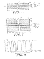
- inventive laser is designated generally at 10.
- the major components of laser 10 are a gain cavity in the form of a single mode optical fiber 12 which comprises a core 14 surrounded by a cladding 16.
- a variable etalon section 18 At the left end of optical fiber 12 is a variable etalon section 18, and at its right end a tuning and frequency modulation section 20, both of which can be integrally formed with the optical fiber 12. Both tuning and modulation could be at the same end.
- Energy from a pump source in the form of a laser diode 22 is preferably coupled into the end of the fiber core 14 through the tuning and frequency modulation section 20 by way of a bulk optical arrangement designated generally at 24.
- the pump source could also couple by a fiber optic element or be butt coupled.
- the laser optical fiber cavity 12 is structured to propagate just single mode over the desired output line width or line to eliminate the effects of modal dispersion known to reduce data transmission rates.
- the diameter of the core will be on the order of a few microns, more or less, while that of the cladding can be conveniently made larger and will be on the order of say, 80 to 100 micrometers, more or less.
- the core 14 and cladding 16 geometry can be non-circular and still be single mode propagating, but if it is of non-circular geometry, the previous equation is only approximately true and is to be applied accordingly.
- the core 14 Having assured that the core 14 propagates at only the wavelength or wavelengths of interest, it is provided with an effective length, L r , at the opposite ends of which are the variable etalon section 18 and the tuning and frequency modulation section 20, both of which are structured to provide feedback to the gain cavity of laser 10 and to modify the resonant characteristics of the gain cavity compared to what they would otherwise be with just ordinary mirrors.
- the output of laser 10 depends on the collective optical action attributable to its effective length.
- L r the reflectivity characteristics of the etalon section 18 and the tuning and frequency modulation section 20, the gain characteristics of the material of which the core 14 is made, and the pump energy level provided by the laser diode 22.
- the effective length, L r determines the frequency or wavelength of the resonances supported in the cavity and is an integral number N of half-wavelengths, i.e., where ⁇ is the free space wavelength and n e is the effective index of the core 14 at the resonant mode.
- the length of the single mode optical fiber 12 is approximated so that its resonant cavity core 14 will resonate at modes which contain the single mode, or adjacent group of modes, desired, keeping in mind that the reflection characteristics of sections 18 and 20 have an effect on the true effective length and thus on which of these modes are possible, particularly section 18, as will subsequently be seen.
- lasers according to the invention can reasonably be expected to range in length from say a few meters down to one millimeter.
- the variable etalon section 18 includes two spaced apart parallel filters, 28 and 30, which are separated by an electro-optical material 32 of nominal thickness, d.
- the electro-optic material 32 preferably is one which has a high electro-optic coefficient and is transparent to radiation at wavelengths desired as output from the laser 10.
- the filters, 28 and 30, are made dichroic so as not to transmit undesired wavelengths back to the fiber core 14 and, along with the electro-optic material 32, are arranged to be perpendiclar to the optical axis of ity, R, at normal incidence, wavelength ⁇ , thickness, d, and index of refraction n is given by: where ⁇ is equal to 2 ⁇ nd/ ⁇ and r1 and r2 are the reflectivities of the two filters, 28 and 30, neglecting phase displacements at the surfaces due to coatings from which the filters, 28 and 30, are preferably formed.
- the reflection characteristics of the individual filters, 28 and 30, are preferably achieved using well-known interference filter coatings.
- the tuning and frequency modulation section 34 and 36 which are also arranged to be perpendicular to the optical axis of the optical fiber core 14, and these filters are also separated by a very thin electrooptical material 38, preferably with conductive coatings for selectively applying electric fields for reasons to follow.
- the filters, 34 and 36 are also dichroic and, in the direction of incoming energy, are highly transmissive to the pump energy wavelength but highly reflective with respect to the output operating wavelength of the laser 10 so as to provide the necessary feedback for laser action.
- a satisfactory value for the joint reflectivity of the filters, 28 and 30, is 85% and individually 50% while 50% has been satisfactory for the filter 34, and for the filter 36, close to 100%.
- the optical fiber laser is placed inside of a glass capillary tube 26 and is potted there to remain fixed in place.
- the ends of this tube, along with the optical fiber 12 are ground and polished and the filter sections, 18 and 20, are then coupled to the polished ends in a well-known manner.
- the capillary tube 26 both aids in the fabrication of the end sections and provides a means for easily handling laser 10.
- the outside diameter of the capillary tube 26 is made to be several millimeters, or more, for convenience.
- an atomic medium with an inverted population is capable of amplifying an electromagnetic wave if the latter's frequency falls within the transition line shape. If the laser medium is placed inside an optical resonator, the electromagnetic wave bounces back and forth between the two reflectors and picks up an additional amount of energy on each pass between them. If the amplification exceeds the losses caused by imperfect reflection in the mirrors and scattering within the laser medium, the energy stored in the resonator will increase with time. This causes the amplification constant to decrease as a result of the gain saturation. The oscillation level will keep increasing until the saturated gain per pass just equals the losses. At this point, the net gain per pass is unit and no further increase in the radiation intensity is possible.
- the lasing medium be neodymium oxide incorporated into a silicate host glass serving as the base material for the fiber core 14.
- the cladding material is preferably a silicate, but can also be any other suitable material.
- a core material which has been found to be successful is one which is supplied by Schott Glass Technologies, Inc. and designated in their catalog with the identification, LG660 silicate. This is a silicate glass doped with 1 1/2% by weight of neodymium oxide.
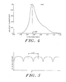
- the absorption spectrum for this material is given in Fig. 3 while its relative fluorescence or emission spectrum is shown in Fig. 4, where it can be seen that there is a peak fluorescent output line at a wavelength of 1.058 micrometers. This is the preferred output wavelength for the laser 10 and, as will be seen, it is possible to achieve this frequency or a small bandwidth of frequencies surrounding it.
- the relative fluorescence spectrum of the core material is quite broad in bandwidth. This is characteristic of a gain material incorporated in a glass base or host material and is a consequence of the amorphous structure of the glass. It is referred to in the art as inhomogeneous broadening and results at least in part from the fact that each ion of the laser material does not experience exactly the same environment within the host material.
- Laser diode 22 is preferably a well-known gallium aluminum arsenide type with a spectral output at approximately .8 micrometers and an emission line confin- ed to a wavelength interval less than 300 angstroms. Its power level is regulated by controlling its injection current, and the bulk optics 24 are preferably chosen to carefully match the NA (numerical aperture) of the laser diode 22 to the NA of the optical fiber 12 which is approximately 0.3, for example.
- these components represent a means by which it is possible to controllably couple energy into the fiber core 12 to cause the popula- tion inversion above threshold to provide lasing action in the cavity and thus satisfy one requirement for con- trolling the laser frequency output.
- the spectral line output of the laser diode 22 occurs at one of the peak absorption bands for the material in the region just above 0.8 micro- meters.
- the reflection characteristic of the etalon section 18 is shown in Fig. 5. As can be seen there, it is periodic in nature, repeating every integral number of wavelengths with maxima separated by one-half wavelength.
- the curve of Fig. 5 represents the reflection characteristic for a given nominal spacing, d. If the spacing, d, changes, then there is a shift in this reflection characteristic along the wavelength axis as shown in Fig. 10.
- Fig. 6 shows how the output of the laser 10 may be made to vary by changing the thickness, d, of the end section 18.
- the output intensity which is for all wavelengths, is represented as some value I0 which would be the output with only one mirror present in the end section 18.
- This output, I0 may be changed in the form of a decaying harmonic function as pictured in Fig. 6 with a maximum value occurring where the thickness, d, is 1/4 wavelength away from no thickness.
- the thickness, d is 1/4 wavelength away from no thickness.
- the thickness, d should be chosen so that it is still within the field location where the wavefronts from the fiber core 14 are still planar, but not so close as to be closer than 1/4 wavelength away from the outside surface of the reflector 30.
- the reflection function of the etalon section 18 has in form an inverted Fabry Perot characteristic which is selected by a careful choice of the design parameters so that, at one of its maximum reflection points, it is aligned with the peak emission line for the fluorescence spectrum of the fiber core material as shown in Fig. 8.
- the separation between maxima, or if you like minimum reflection points, is chosen so that within this bandwidth there exists a number of resonant orders for the fiber core resonant cavity. It has been discovered that orders of the fiber core resonant cavity which are in side orders of the end section 18 resonant filter characteristics are completely suppressed, even when the pumping energy exceeds laser threshold.
- the fiber resonant cavity is made shorter to increase the free spectral range between its resonant modes, it should be possible to even further reduce the number of orders which will resonate to to the point where it is believed that a single order can be achieved.
- the laser pump energy level is increased, more of the resonant orders of the fiber core will be excited and will thus be present, except that orders outside of the peak reflectance region centered on the peak spectral emission line will be excluded from lasing.
- a change in the thickness, d also results in a shift of the reflection characteristic curve of the etalon section 18 along the wavelength axis, and thus, there is a shift in the wavelength under the laser material gain curve at which the laser emits radiation. Consequently, one can also achieve wavelength shifts in the output of the laser by activating the electro-optic material 32. This, however, not only shifts wavelengths, but as also explained, changes intensity. A small amount of modulation could give useful frequency modulation without significant intensity variations.
- the end section 20 can be used as a means for either tuning the laser or as a means for frequency modulating its output without in any way disturbing its overall amplitude.
- use may be made of electronic feedback arrangements to further achieve stability at particular wavelengths.
- the reflectance characteristic for the filters 34 and 36 is shown in generalized form in Fig. 11 and for the particular example given had a high transmission with respect to energy coming from the laser pump system travelling towards the fiber core 14 and a high reflectance with respect to energy propagating in the core towards the end section 20.
- the transmission of the filter 34 is 50%, while that of the filter 36 is as high as possible, approximating 100%.
Landscapes
- Physics & Mathematics (AREA)
- Electromagnetism (AREA)
- Engineering & Computer Science (AREA)
- Plasma & Fusion (AREA)
- Optics & Photonics (AREA)
- Lasers (AREA)
Applications Claiming Priority (2)
| Application Number | Priority Date | Filing Date | Title |
|---|---|---|---|
| US750594 | 1985-07-01 | ||
| US06/750,594 US4680767A (en) | 1985-07-01 | 1985-07-01 | Optical fiber laser |
Publications (3)
| Publication Number | Publication Date |
|---|---|
| EP0208189A2 true EP0208189A2 (fr) | 1987-01-14 |
| EP0208189A3 EP0208189A3 (en) | 1988-12-07 |
| EP0208189B1 EP0208189B1 (fr) | 1994-06-01 |
Family
ID=25018484
Family Applications (1)
| Application Number | Title | Priority Date | Filing Date |
|---|---|---|---|
| EP86108550A Expired - Lifetime EP0208189B1 (fr) | 1985-07-01 | 1986-06-23 | Laser à fibre optique |
Country Status (5)
| Country | Link |
|---|---|
| US (1) | US4680767A (fr) |
| EP (1) | EP0208189B1 (fr) |
| JP (1) | JPH0744303B2 (fr) |
| CA (1) | CA1253947A (fr) |
| DE (2) | DE3689864T2 (fr) |
Cited By (8)
| Publication number | Priority date | Publication date | Assignee | Title |
|---|---|---|---|---|
| US4782491A (en) * | 1987-04-09 | 1988-11-01 | Polaroid Corporation | Ion doped, fused silica glass fiber laser |
| US4847851A (en) * | 1988-05-19 | 1989-07-11 | University Of South Florida | Butt-coupled single transverse mode diode pumped laser |
| GB2180392B (en) * | 1985-08-13 | 1989-10-11 | Robert Joseph Mears | Fibre-optic lasers and amplifiers |
| GB2241109A (en) * | 1990-01-19 | 1991-08-21 | Mitsubishi Electric Corp | A semiconductor-laser-pumped, solid-state laser |
| US5257277A (en) * | 1990-01-19 | 1993-10-26 | Mitsubishi Denki Kabushiki Kaisha | Semiconductor-laser-pumped, solid-state laser |
| US7576909B2 (en) | 1998-07-16 | 2009-08-18 | Imra America, Inc. | Multimode amplifier for amplifying single mode light |
| US7656578B2 (en) | 1997-03-21 | 2010-02-02 | Imra America, Inc. | Microchip-Yb fiber hybrid optical amplifier for micro-machining and marking |
| US8761211B2 (en) | 1998-11-25 | 2014-06-24 | Imra America, Inc. | Multi-mode fiber amplifier |
Families Citing this family (34)
| Publication number | Priority date | Publication date | Assignee | Title |
|---|---|---|---|---|
| JPH0740617B2 (ja) * | 1986-08-08 | 1995-05-01 | 日本電信電話株式会社 | 光フアイバレ−ザ |
| GB2202404B (en) * | 1987-03-13 | 1991-01-02 | Plessey Co Plc | Apparatus for optical wavelength division multiplexing |
| JP2662780B2 (ja) * | 1987-03-27 | 1997-10-15 | 憲一 植田 | 自由電子レーザ装置 |
| USRE33722E (en) * | 1987-04-28 | 1991-10-22 | Spectra Diode Laboratories, Inc. | Optical system with bright light output |
| US4763975A (en) * | 1987-04-28 | 1988-08-16 | Spectra Diode Laboratories, Inc. | Optical system with bright light output |
| US4818062A (en) * | 1987-04-28 | 1989-04-04 | Spectra Diode Laboratories, Inc. | Optical system with bright light output |
| US4922496A (en) * | 1987-12-17 | 1990-05-01 | Polaroid Corporation | Armonic generation in optical fibers |
| US4859015A (en) * | 1988-08-17 | 1989-08-22 | The Boeing Company | Optical receiver having optical gain medium and mode selector |
| US4971417A (en) * | 1989-08-23 | 1990-11-20 | The Boeing Company | Radiation-hardened optical repeater |
| US5022745A (en) * | 1989-09-07 | 1991-06-11 | Massachusetts Institute Of Technology | Electrostatically deformable single crystal dielectrically coated mirror |
| US5172391A (en) * | 1991-01-09 | 1992-12-15 | Massachusetts Institute Of Technology | Polarization controlling system for lasers |
| JP2693662B2 (ja) * | 1991-07-16 | 1997-12-24 | 株式会社東芝 | 光増幅装置 |
| US5283845A (en) * | 1992-07-20 | 1994-02-01 | Jds Fitel Inc. | Multi-port tunable fiber-optic filter |
| WO1994017575A1 (fr) * | 1993-01-22 | 1994-08-04 | Deutsche Forschungsanstalt für Luft- und Raumfahrt e.V. | Systeme laser fractal pilote en phase |
| US5425039A (en) * | 1994-02-24 | 1995-06-13 | Micron Optics, Inc. | Single-frequency fiber Fabry-Perot micro lasers |
| US6137812A (en) * | 1994-02-24 | 2000-10-24 | Micron Optics, Inc. | Multiple cavity fiber fabry-perot lasers |
| US5847853A (en) | 1995-12-29 | 1998-12-08 | Micron Technology, Inc. | Modulation and demodulation of light to facilitate transmission of information |
| DE19723267A1 (de) * | 1997-06-03 | 1998-12-10 | Heidelberger Druckmasch Ag | Verfahren und Anordnung zur Reduzierung des Pumplichts am Austritt eines Fiberlasers |
| US6016371A (en) * | 1997-12-19 | 2000-01-18 | Trw Inc. | Optical RF signal processing |
| JP3250609B2 (ja) * | 1998-07-01 | 2002-01-28 | 日本電気株式会社 | レーザ発振装置、レーザメス |
| CA2256963A1 (fr) * | 1998-12-23 | 2000-06-23 | Nigel Copner | Cavite optique resonante a trois ports |
| DE10018778A1 (de) * | 2000-04-15 | 2001-10-18 | Zeiss Carl Jena Gmbh | Verfahren und Anordnung zur Selbstkalibrierung eines diodengepumpten Festkörperlasers, insbesondere eines durchstimmbaren, diodengepumpten Festkörperlasers |
| US6636675B2 (en) | 2001-03-12 | 2003-10-21 | Verrillon, Inc. | Optical fiber with reduced cladding-mode loss |
| US6728274B1 (en) * | 2001-09-14 | 2004-04-27 | Multiwave Networks Portugal Lda | Multi-wavelength laser apparatus and method |
| US6816514B2 (en) | 2002-01-24 | 2004-11-09 | Np Photonics, Inc. | Rare-earth doped phosphate-glass single-mode fiber lasers |
| EP1558955A4 (fr) * | 2002-10-15 | 2006-04-19 | Micron Optics Inc | Filtres fabry-perot a fibre sans plaquette |
| KR20040047254A (ko) * | 2002-11-29 | 2004-06-05 | 한국전자통신연구원 | 에탈론 필터가 집적된 파장가변 레이저 다이오드 광학기구 |
| WO2004059357A1 (fr) * | 2002-12-20 | 2004-07-15 | Micron Optics, Inc. | Support de ferrule a compensation thermique pour un filtre fabry-perot a fibre |
| DE10302031A1 (de) * | 2003-01-21 | 2004-09-23 | Evotec Oai Ag | Faser-Laser |
| US7283242B2 (en) * | 2003-04-11 | 2007-10-16 | Thornton Robert L | Optical spectroscopy apparatus and method for measurement of analyte concentrations or other such species in a specimen employing a semiconductor laser-pumped, small-cavity fiber laser |
| US7633621B2 (en) * | 2003-04-11 | 2009-12-15 | Thornton Robert L | Method for measurement of analyte concentrations and semiconductor laser-pumped, small-cavity fiber lasers for such measurements and other applications |
| WO2005067110A2 (fr) * | 2003-09-02 | 2005-07-21 | Thornton Robert L | Appareil de spectroscopie optique et methode pour mesurer des concentrations d'analyte ou d'une autre espece dans un echantillon, au moyen d'un laser a fibre a petite cavite a pompage par laser semi-conducteur |
| US20050169339A1 (en) * | 2004-02-04 | 2005-08-04 | Cumbo Michael J. | Monolithic wafer-scale waveguide-laser |
| GB0520853D0 (en) * | 2005-10-14 | 2005-11-23 | Gsi Lumonics Ltd | Optical fibre laser |
Family Cites Families (8)
| Publication number | Priority date | Publication date | Assignee | Title |
|---|---|---|---|---|
| US4044315A (en) * | 1962-01-16 | 1977-08-23 | American Optical Corporation | Means for producing and amplifying optical energy |
| US3599106A (en) * | 1968-11-06 | 1971-08-10 | American Optical Corp | High intensity-high coherence laser system |
| CA944466A (en) * | 1970-01-26 | 1974-03-26 | Western Electric Company, Incorporated | Guided raman devices |
| US3725814A (en) * | 1971-09-10 | 1973-04-03 | Us Air Force | Apparatus for locking the frequency of a laser to an atomic absorption line |
| US3830557A (en) * | 1972-06-19 | 1974-08-20 | Trw Inc | Laser q-switching |
| US3958188A (en) * | 1974-12-11 | 1976-05-18 | Nasa | Fiber distributed feedback laser |
| US4001705A (en) * | 1975-05-20 | 1977-01-04 | Brett Jason Sinclair | Light scanning device |
| US4358851A (en) * | 1980-02-28 | 1982-11-09 | Xerox Corporation | Fiber optic laser device and light emitter utilizing the device |
-
1985
- 1985-07-01 US US06/750,594 patent/US4680767A/en not_active Expired - Lifetime
-
1986
- 1986-06-18 CA CA000511835A patent/CA1253947A/fr not_active Expired
- 1986-06-23 DE DE3689864T patent/DE3689864T2/de not_active Expired - Fee Related
- 1986-06-23 DE DE198686108550T patent/DE208189T1/de active Pending
- 1986-06-23 EP EP86108550A patent/EP0208189B1/fr not_active Expired - Lifetime
- 1986-06-30 JP JP61153962A patent/JPH0744303B2/ja not_active Expired - Lifetime
Cited By (15)
| Publication number | Priority date | Publication date | Assignee | Title |
|---|---|---|---|---|
| GB2180392B (en) * | 1985-08-13 | 1989-10-11 | Robert Joseph Mears | Fibre-optic lasers and amplifiers |
| US4782491A (en) * | 1987-04-09 | 1988-11-01 | Polaroid Corporation | Ion doped, fused silica glass fiber laser |
| US4847851A (en) * | 1988-05-19 | 1989-07-11 | University Of South Florida | Butt-coupled single transverse mode diode pumped laser |
| WO1989011742A1 (fr) * | 1988-05-19 | 1989-11-30 | University Of South Florida | Laser pompe par une diode a mode transversal simple et a accouplement en bout a bout |
| US5257277A (en) * | 1990-01-19 | 1993-10-26 | Mitsubishi Denki Kabushiki Kaisha | Semiconductor-laser-pumped, solid-state laser |
| US5159605A (en) * | 1990-01-19 | 1992-10-27 | Mitsubishi Denki Kabushiki Kaisha | Semiconductor-laser-pumped, solid-state laser |
| GB2241109A (en) * | 1990-01-19 | 1991-08-21 | Mitsubishi Electric Corp | A semiconductor-laser-pumped, solid-state laser |
| GB2241109B (en) * | 1990-01-19 | 1994-09-14 | Mitsubishi Electric Corp | A semiconductor-laser-pumped,solid-state laser |
| US7656578B2 (en) | 1997-03-21 | 2010-02-02 | Imra America, Inc. | Microchip-Yb fiber hybrid optical amplifier for micro-machining and marking |
| US7576909B2 (en) | 1998-07-16 | 2009-08-18 | Imra America, Inc. | Multimode amplifier for amplifying single mode light |
| US8761211B2 (en) | 1998-11-25 | 2014-06-24 | Imra America, Inc. | Multi-mode fiber amplifier |
| US9153929B2 (en) | 1998-11-25 | 2015-10-06 | Imra America, Inc. | Mode-locked multi-mode fiber laser pulse source |
| US9450371B2 (en) | 1998-11-25 | 2016-09-20 | Imra America, Inc. | Mode-locked multi-mode fiber laser pulse source |
| US9570880B2 (en) | 1998-11-25 | 2017-02-14 | Imra America, Inc. | Multi-mode fiber amplifier |
| US9595802B2 (en) | 1998-11-25 | 2017-03-14 | Imra America, Inc. | Multi-mode fiber amplifier |
Also Published As
| Publication number | Publication date |
|---|---|
| DE3689864T2 (de) | 1994-09-08 |
| DE3689864D1 (de) | 1994-07-07 |
| US4680767A (en) | 1987-07-14 |
| EP0208189A3 (en) | 1988-12-07 |
| JPH0744303B2 (ja) | 1995-05-15 |
| DE208189T1 (de) | 1987-04-30 |
| JPS6225481A (ja) | 1987-02-03 |
| EP0208189B1 (fr) | 1994-06-01 |
| CA1253947A (fr) | 1989-05-09 |
Similar Documents
| Publication | Publication Date | Title |
|---|---|---|
| US4680767A (en) | Optical fiber laser | |
| US4780877A (en) | Optical fiber laser | |
| EP1668751B1 (fr) | Commande de phase dans un laser accordable a cavite externe | |
| US7599405B2 (en) | Method and apparatus for coherently combining multiple laser oscillators | |
| US5243609A (en) | Laser with longitudinal mode selection | |
| US5255274A (en) | Broadband laser source | |
| CA2064488C (fr) | Laser en anneau a fibres electriquement accordable | |
| US7720117B2 (en) | Fast continuously wavelength tuning single frequency fiber laser using tunable polymer optical filters | |
| US5189676A (en) | Broadband laser source | |
| US6347104B1 (en) | Optical signal power monitor and regulator | |
| AU734315B2 (en) | Rare-earth doped lithium niobate DBR laser | |
| US8619824B2 (en) | Low white frequency noise tunable semiconductor laser source | |
| US5463647A (en) | Broadband multi-wavelength narrow linewidth laser source using an electro-optic modulator | |
| US20050147355A1 (en) | Optical coupling for whispering-gallery-mode resonators via waveguide gratings | |
| WO2004049525A1 (fr) | Lasers a verrouillage des modes actifs et autres dispositifs photoniques utilisant des resonateurs a modes de galerie electro-optiques | |
| EP0300790B1 (fr) | Laser à semi-conducteur | |
| US6628696B2 (en) | Multi-channel DWDM transmitter based on a vertical cavity surface emitting laser | |
| JPH0449793B2 (fr) | ||
| US6788715B1 (en) | Stabilized laser using multiphoton absorption to reduce intensity fluctuations | |
| US6816534B2 (en) | Tunable single frequency filter for lasers | |
| EP1087477B1 (fr) | Module laser à semi-conducteur | |
| Jones et al. | An injection-locked erbium fibre laser | |
| WO2004068652A2 (fr) | Procede et appareil pour combiner des oscillateurs a laser | |
| US6005877A (en) | Distributed-feedback fiber-laser with asymmetric output ports | |
| Gloag et al. | Tunable, single frequency erbium fiber laser using an overlay bandpass filter |
Legal Events
| Date | Code | Title | Description |
|---|---|---|---|
| PUAI | Public reference made under article 153(3) epc to a published international application that has entered the european phase |
Free format text: ORIGINAL CODE: 0009012 |
|
| AK | Designated contracting states |
Kind code of ref document: A2 Designated state(s): DE FR GB NL |
|
| TCNL | Nl: translation of patent claims filed | ||
| EL | Fr: translation of claims filed | ||
| DET | De: translation of patent claims | ||
| PUAL | Search report despatched |
Free format text: ORIGINAL CODE: 0009013 |
|
| AK | Designated contracting states |
Kind code of ref document: A3 Designated state(s): DE FR GB NL |
|
| 17P | Request for examination filed |
Effective date: 19890522 |
|
| 17Q | First examination report despatched |
Effective date: 19910703 |
|
| GRAA | (expected) grant |
Free format text: ORIGINAL CODE: 0009210 |
|
| AK | Designated contracting states |
Kind code of ref document: B1 Designated state(s): DE FR GB NL |
|
| ET | Fr: translation filed | ||
| REF | Corresponds to: |
Ref document number: 3689864 Country of ref document: DE Date of ref document: 19940707 |
|
| PLBE | No opposition filed within time limit |
Free format text: ORIGINAL CODE: 0009261 |
|
| STAA | Information on the status of an ep patent application or granted ep patent |
Free format text: STATUS: NO OPPOSITION FILED WITHIN TIME LIMIT |
|
| 26N | No opposition filed | ||
| REG | Reference to a national code |
Ref country code: FR Ref legal event code: TP |
|
| REG | Reference to a national code |
Ref country code: GB Ref legal event code: 732E |
|
| NLS | Nl: assignments of ep-patents |
Owner name: SDL, INC. |
|
| REG | Reference to a national code |
Ref country code: GB Ref legal event code: IF02 |
|
| PGFP | Annual fee paid to national office [announced via postgrant information from national office to epo] |
Ref country code: FR Payment date: 20020530 Year of fee payment: 17 |
|
| PGFP | Annual fee paid to national office [announced via postgrant information from national office to epo] |
Ref country code: NL Payment date: 20020610 Year of fee payment: 17 |
|
| PGFP | Annual fee paid to national office [announced via postgrant information from national office to epo] |
Ref country code: GB Payment date: 20020619 Year of fee payment: 17 |
|
| PGFP | Annual fee paid to national office [announced via postgrant information from national office to epo] |
Ref country code: DE Payment date: 20020620 Year of fee payment: 17 |
|
| NLS | Nl: assignments of ep-patents |
Owner name: JDS UNIPHASE CORPORATION |
|
| REG | Reference to a national code |
Ref country code: GB Ref legal event code: 732E |
|
| PG25 | Lapsed in a contracting state [announced via postgrant information from national office to epo] |
Ref country code: GB Free format text: LAPSE BECAUSE OF NON-PAYMENT OF DUE FEES Effective date: 20030623 |
|
| PG25 | Lapsed in a contracting state [announced via postgrant information from national office to epo] |
Ref country code: NL Free format text: LAPSE BECAUSE OF NON-PAYMENT OF DUE FEES Effective date: 20040101 Ref country code: DE Free format text: LAPSE BECAUSE OF NON-PAYMENT OF DUE FEES Effective date: 20040101 |
|
| GBPC | Gb: european patent ceased through non-payment of renewal fee |
Effective date: 20030623 |
|
| PG25 | Lapsed in a contracting state [announced via postgrant information from national office to epo] |
Ref country code: FR Free format text: LAPSE BECAUSE OF NON-PAYMENT OF DUE FEES Effective date: 20040227 |
|
| NLV4 | Nl: lapsed or anulled due to non-payment of the annual fee |
Effective date: 20040101 |
|
| REG | Reference to a national code |
Ref country code: FR Ref legal event code: ST |