EP0208302A1 - Markise für Verkaufsstände - Google Patents
Markise für Verkaufsstände Download PDFInfo
- Publication number
- EP0208302A1 EP0208302A1 EP86109332A EP86109332A EP0208302A1 EP 0208302 A1 EP0208302 A1 EP 0208302A1 EP 86109332 A EP86109332 A EP 86109332A EP 86109332 A EP86109332 A EP 86109332A EP 0208302 A1 EP0208302 A1 EP 0208302A1
- Authority
- EP
- European Patent Office
- Prior art keywords
- post
- shaft
- awning
- cloth
- roof
- Prior art date
- Legal status (The legal status is an assumption and is not a legal conclusion. Google has not performed a legal analysis and makes no representation as to the accuracy of the status listed.)
- Granted
Links
- 239000004744 fabric Substances 0.000 claims abstract description 44
- 230000001681 protective effect Effects 0.000 claims abstract description 4
- 125000006850 spacer group Chemical group 0.000 claims description 9
- CNQCVBJFEGMYDW-UHFFFAOYSA-N lawrencium atom Chemical compound [Lr] CNQCVBJFEGMYDW-UHFFFAOYSA-N 0.000 description 8
- 238000010276 construction Methods 0.000 description 4
- 230000001154 acute effect Effects 0.000 description 1
- 238000011109 contamination Methods 0.000 description 1
- 210000000629 knee joint Anatomy 0.000 description 1
- 210000002414 leg Anatomy 0.000 description 1
Images





Classifications
-
- B—PERFORMING OPERATIONS; TRANSPORTING
- B60—VEHICLES IN GENERAL
- B60P—VEHICLES ADAPTED FOR LOAD TRANSPORTATION OR TO TRANSPORT, TO CARRY, OR TO COMPRISE SPECIAL LOADS OR OBJECTS
- B60P3/00—Vehicles adapted to transport, to carry or to comprise special loads or objects
- B60P3/025—Vehicles adapted to transport, to carry or to comprise special loads or objects the object being a shop, cafeteria or display the object being a theatre or stage
- B60P3/0255—Vehicles adapted to transport, to carry or to comprise special loads or objects the object being a shop, cafeteria or display the object being a theatre or stage the object being a display, i.e. for displaying articles
-
- E—FIXED CONSTRUCTIONS
- E04—BUILDING
- E04H—BUILDINGS OR LIKE STRUCTURES FOR PARTICULAR PURPOSES; SWIMMING OR SPLASH BATHS OR POOLS; MASTS; FENCING; TENTS OR CANOPIES, IN GENERAL
- E04H1/00—Buildings or groups of buildings for dwelling or office purposes; General layout, e.g. modular co-ordination or staggered storeys
- E04H1/12—Small buildings or other erections for limited occupation, erected in the open air or arranged in buildings, e.g. kiosks, waiting shelters for bus stops or for filling stations, roofs for railway platforms, watchmen's huts or dressing cubicles
- E04H1/1205—Small buildings erected in the open air
- E04H1/1222—Sales kiosks
-
- E—FIXED CONSTRUCTIONS
- E04—BUILDING
- E04H—BUILDINGS OR LIKE STRUCTURES FOR PARTICULAR PURPOSES; SWIMMING OR SPLASH BATHS OR POOLS; MASTS; FENCING; TENTS OR CANOPIES, IN GENERAL
- E04H15/00—Tents or canopies, in general
- E04H15/02—Tents combined or specially associated with other devices
-
- E—FIXED CONSTRUCTIONS
- E04—BUILDING
- E04H—BUILDINGS OR LIKE STRUCTURES FOR PARTICULAR PURPOSES; SWIMMING OR SPLASH BATHS OR POOLS; MASTS; FENCING; TENTS OR CANOPIES, IN GENERAL
- E04H15/00—Tents or canopies, in general
- E04H15/32—Parts, components, construction details, accessories, interior equipment, specially adapted for tents, e.g. guy-line equipment, skirts, thresholds
- E04H15/58—Closures; Awnings; Sunshades
Definitions
- the present application relates to an awning roof for sales stands or the like with a rotatably mounted cloth shaft with two wound cloths, which are attached at their freely extractable edges to rods parallel to the cloth shaft, which can be moved symmetrically outwards when the cloth shaft is rotated by means of a drive with simultaneous handling of the two cloths, so that the cloths, when extended, form a protective roof that is inclined outwards from the center.
- an awning roof of the type mentioned at the outset has become known, which can be attached to the roof of a vehicle.
- the rods to which the fabric sheets are attached are moved outwards by means of several telescopically extendable rods.
- the extendable poles are mounted on four height-adjustable rigid posts on the vehicle roof.
- the system of the telescopically extendable rods is structurally very complex and also prone to contamination. Because the posts that support the awning roof are each arranged in the four corners of the available rectangular roof area, the awning roof can only be moved together until the rods abut the posts. The dismantling of the awning roof construction from the vehicle roof is also quite complex.
- the object of the present invention is therefore to improve an awning roof of the type mentioned in such a way that assembly and disassembly, handling and transport are facilitated and the two halves of the roof can be completely moved together.
- At least one post is provided below the axis of the fabric shaft for the awning roof according to the invention.
- the rods, to which the cloths are attached are extended by means of a system of toggle levers, which are in turn articulated to the support, which is located below the cloth shaft. In this way it is possible to completely move the opposite parallel rods and thus the two fabric sheets up to the fabric shaft.
- the awning roof according to the invention is intended for a mobile sales stand, for example a sales trailer that can be attached to a motor vehicle
- two posts are preferably provided on the front and on the back of the trailer. Due to the special design of the posts, it is possible to completely fold the awning roof up after moving the covers together, into a movable transport position in which the overall height of the sales trailer is only very low.
- the roof structure can be covered with a tarpaulin during transport. It is particularly advantageous that the construction of the post elements is such that one person can easily set up the awning roof, which is in the transport position can. How the posts are set up in detail is described in the figure description as an example.
- a further sheet of cloth is provided which can be attached to one long side of one of the two rods and which extends vertically downward.
- This awning also closes the back of the sales booth. So that the awning cloth does not flutter, a spacer is preferably provided on both ends of the sales stand, on which the awning is fixed, for example with a push button. The awning is thus kept under tension. If the sales stand is a mobile sales trailer, the spacer for the awning on the long side can also serve to support the sales trailer against tipping.
- the use of the awning roof according to the invention is not limited to mobile sales stands, but it can also be attached to a sales table, for example.
- the awning roof can also serve as a sun roof for a balcony or terrace. With the latter use, it is advantageous if only one post is provided below the fabric shaft. So that the largest possible area can be shielded against incident sunlight with such an awning roof, it is mounted in a suitable holder so that it can be rotated through 360 ° about its vertical axis.
- the carrier can be supported below the fabric shaft with an additional support that runs at an acute angle to the post.
- a base is provided in a manner known per se.
- Figure 1 shows an awning roof 10 on a sales cart 100 in the folded transport position.
- Fixed post elements 101, 111 are fastened to the end faces of the sales trailer 100 with rivets, screws or the like.
- joints 102, 112 At the upper end of these fixed post elements there are joints 102, 112 for the articulated connection to further post elements 103, 113, which in the position shown lie in a horizontal position on the sales trailer 100.
- the ends of the post elements 103, 113 are in turn connected via joints 104, 114 at their ends to further post elements 105, 115, which lie approximately congruently on the post elements 103, 113 in the transport position shown.
- the post elements 105, 115 are in turn connected at their ends via joints 106, 116 and tabs to the carrier 107 for the awning roof.
- the illustration is schematically simplified for the sake of clarity. The articulated connections are explained in more detail below with the aid of further figures.
- the fabric sheets 110 for the awning roof are here in the rolled-up state. If the awning roof is to be erected, the support 107 is first raised on one of the two sides in the direction of arrow A and the roof is pivoted upwards until the post elements 103, 105 are aligned with one another. Means are provided on the joint 104, which is shown in more detail in FIGS. 7 and 8, in order to fix the post elements 103, 105 so that there is a rigid connection between them.
- the awning roof is now in the position shown in Figure 2.
- the carrier 107 is now raised on the right side in the illustration in the direction of the arrow B and is pulled somewhat to the side away from the sales car.
- the post swings out of the post elements 103, 105 a little clockwise around the joint 102 in the direction of the arrow C.
- the post element 113 is pivoted about the joint 112, clockwise until it is in a vertical position and with the fixed post element 111 is aligned.
- FIG. 3 The position shown in FIG. 3 has now been reached.
- means 146 are provided which allow the post element 113 to be fixed in the vertical position on the post element 111.
- the awning roof on the right side in the illustration according to FIG. 3 is pivoted further in the direction of arrow D.
- the post element 115 pivots counterclockwise around the joint 114 until this post element 115 is also vertical and thus with the lower post element 113 is aligned.
- the post element 115 can then be fixed to the post element 113 by means of a locking screw 141 (FIG. 8) of the joint 114, which corresponds to the joint 104.
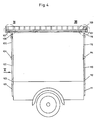
- FIG. 5 shows the awning roof according to the invention on a mobile sales trailer in an upright position in the side view of FIG. 4.
- the two wound fabrics 130, 131 which are at their freely removable edges are attached to rods 109, 119 parallel to the fabric shaft.
- the toggle levers 121, 125 are each connected via joints 123, 127 to the carrier 107 located under the fabric shaft 120.
- an additional sheet of fabric 132 is provided, which extends along a long side of the sales stand and is fixed to the rod 119 at its upper end.
- the sheet of cloth 132 is on the right and left by means of push buttons or the like fixed on a spacer and thus kept under tension.
- the spacer is approximately L-shaped in the side view and consists of two rods or tubes 134, 135.
- the rod 135 of the spacer is articulated to the trailer by means of a joint 136.
- the fastening 133 is released and the spacer is pivoted 180 ° clockwise around the joint 136, so that it is then in the position shown in broken lines.
- a bracket 137 is provided on the trailer, which receives the leg 134 of the spacer in this rest position.
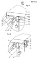
- the joint 104 between the two post elements 103 and 105 is shown in more detail in FIGS. 7 and 8.
- a plate 140 is provided, which is connected in its upper region to the upper post element 105 by means of a welded connection.
- the plate 140 has an internal thread 143 in its lower region.
- a bore 142 is provided in the post element 103 for a wing screw 141, so that when the two post elements 103, 105 are connected in a straight line, the plate 140 can be screwed against the post element 103 by means of the wing screw 141 . After loosening the screw 141, the post element 103 can be pivoted clockwise against the post element 105.
- a hinge pin 139 is provided for the joint, which is articulated in two brackets 138, 150, the brackets being firmly connected to the lower post element 103.
- the joint 102 is shown in more detail in FIGS. 9 and 10.
- Two tabs 144, 147 are provided, which are firmly connected to the post element 103 at the top and between which the lower post element 101 is recorded. At the bottom, the two tabs are connected by a plate 145.
- the plate 145 is fixed to this post element by means of the wing screw 146, for which a threaded bore 149 is provided in the post element 101. After loosening the screw 146, the post element 103 is rotated about the hinge pin 102.
- the lower post element 101 is fixed in the vertical position at the sales stand by fastening means 148.
- FIG. 1 Another preferred embodiment of the invention is shown in FIG.
- only one post 163 arranged below the fabric shaft is provided for the awning roof.
- the fabric shaft can be supported by an additional support arm 162.
- the post 163 is rotatably supported in a sleeve 160 or the like about its vertical axis. If necessary, the post 163 is rotated about this axis, depending on the direction of the sun, so that the awning roof can shield a larger area from the sun.
- a base 161 is provided in order to ensure the necessary stability of the awning roof according to this embodiment.
- the upper post member 105 is pivotally connected at its upper end around the horizontal axis 106 of a joint, which to 'he stands the axis of the cloth shaft 120 vertically d with the carrier (107).
- the carrier 107 On the carrier 107, two tabs 166 are attached, between which the post element 105 is received.
- the rotary movement takes place around a rotatably mounted hinge pin.
- the post element 105 has two further tabs 165, between which the lower post element 103 lies in the folded state (FIG. 1).
- the two joint forks 169, 170 are connected by means of a joint bolt in such a way that the joint fork 170 can rotate in the joint fork 169 about the horizontal joint axis 168.
- the articulated fork 170 is configured in a ring shape at its end facing the toggle lever 121 (not shown).
- another articulation pin is rotatably mounted, which in turn is firmly connected to the end of the toggle lever 121 by means of pins or the like. This allows the toggle lever 121 to rotate relative to the articulated fork 170 about the vertical articulated axis 167.
- connection between the toggle lever 121 and the carrier 107 is thus a type of universal joint, since on the one hand a rotation about the vertical axis 167 and on the other hand a rotation about the further horizontal axis 168, which is perpendicular to the first axis 167, can take place.
- the universal joint is necessary so that the rods 109, 119 can be extended laterally by means of the toggle levers 121, 122 or 125, 126. In the embodiment with two posts, a total of four such universal joints are required.
- the upper post element 115 is articulated in the same way as the post element 105 via two brackets 172 and a hinge pin at the upper end to the carrier 107.
- the cloth shaft 120 is lined with an aperture 164 and 176 at the end.
- the cloth shaft is driven manually by means of a rod 173 which engages with a hook in a ring at its upper end.
- the ring is fixedly connected to a bolt 175 which is rotatably mounted in a housing 174 about a vertical axis. Suitable gear means are provided (not by means of which the rotation of the pin 175 about its vertical axis is converted into a rotation of the cloth shaft 120 about its horizontal axis.
Landscapes
- Engineering & Computer Science (AREA)
- Architecture (AREA)
- Civil Engineering (AREA)
- Structural Engineering (AREA)
- Health & Medical Sciences (AREA)
- Public Health (AREA)
- Transportation (AREA)
- Mechanical Engineering (AREA)
- Tents Or Canopies (AREA)
- Building Awnings And Sunshades (AREA)
Abstract
Description
- Die vorliegende Anmeldung betrifft ein Markisendach für Verkaufsstände oder dergleichen mit einer drehbar gelagerten Tuchwelle mit zwei aufgewickelten Tüchern, die an ihren frei herausziehbaren Rändern an zur Tuchwelle parallelen Stäben befestigt sind, die bei Drehung der Tuchwelle mittels eines Antriebs symmetrisch nach außen fahrbar sind unter gleichzeitiger Abwicklung der beiden Tücher, so daß die Tücher im ausgefahrenen Zustand ein von der Mitte jeweils nach außen geneigtes Schutzdach bilden.
- Aus der US-Patentschrift 3952 758 ist ein Markisendach der eingangs genannten Art bekannt geworden, das auf dem Dach eines Fahrzeugs anbringbar ist. Bei dem bekannten Markisendach werden die Stäbe, an denen die Tuchbahnen befestigt sind, mittels mehrerer teleskopartig ausfahrbarer Stangen nach außen bewegt. Die ausfahrbaren Stangen sind auf vier höhenverstellbaren starren Pfosten auf dem Fahrzeugdach gelagert. Das System der teleskopartig ausfahrbaren Stangen ist konstruktiv sehr aufwendig und außerdem anfällig gegen Verschmutzung. Dadurch, daß die Pfosten, die das Markisendach tragen, jeweils in den vier Ecken der zur Verfügung stehenden rechteckigen Dachfläche angeordnet sind, kann das Markisendach nur so weit zusammengefahren werden, bis die Stäbe an den Pfosten anliegen. Auch ist die Demontage der Markisendachkonstruktion vom Fahrzeugdach recht aufwendig.
- Die Aufgabe der vorliegenden Erfindung besteht deshalb darin, ein Markisendach der eingangs genannten Art dahingehend zu verbessern, daß Auf- und Abbau, Handhabung und Transport erleichtert werden und das völlige Zusammenfahren der beiden Dachhälften möglich ist.
- Die Lösung dieser Aufgabe ergibt sich durch ein Markisendach mit den Merkmalen des Hauptanspruchs. Die in den Unteransprüchen genannten Merkmale beziehen sich auf vorteilhafte Ausführungsformen der Erfindung.
- Für das erfindungsgemäße Markisendach ist mindestens ein Pfosten unterhalb der Achse der Tuchwelle vorgesehen.
- Das Ausfahren der Stäbe, an denen die Tücher befestigt sind, geschieht mittels eines Systems von Kniehebeln, die wiederum mit dem Träger, der sich unterhalb der Tuchwelle befindet, gelenkig verbunden sind. Auf diese Weise ist es möglich die gegenüberliegenden parallelen Stäbe und damit die beiden Tuchbahnen bis an die Tuchwelle völlig zusammenzufahren.
- Wenn das erfindungsgemäße Markisendach für einen fahrbaren Verkaufsstand vorgesehen ist, beispielsweise einen an ein Kraftfahrzeug anhängbaren Verkaufsanhänger, sind vorzugsweise zwei Pfosten, an der Vorder- und an der Rückseite des Anhängers vorgesehen. Durch die besondere Ausbildung der Pfosten ist es möglich, das Markisendach nach dem Zusammenfahren der Tücher vollständig zusammenzuklappen, in eine verfahrbare Transportstellung, in der die Gesamthöhe des Verkaufsanhängers nur noch sehr gering ist. Zum Schutz kann die Dachkonstruktion beim Transport mit einer Plane abgedeckt werden. Es ist von besonderem Vorteil, daß die Konstruktion der Pfostenelemente so ist, daß eine Person allein ohne Mühe das Markisendach, das sich in der Transportstellung befindet,aufstellen kann. Wie das Aufstellen der Pfosten im einzelnen erfolgt, ist in der Figurenbeschreibung beispielhaft beschrieben.
- Gemäß einer bevorzugten Ausführungsform der Erfindung ist eine weitere Tuchbahn vorgesehen, die an einer Längsseite eines der beiden Stäbe anbringbar ist und sich vertikal nach unten erstreckt. Durch diese Markise ist zusätzlich auch die Rückseite des Verkaufsstandes geschlossen. Damit das Markisentuch nicht flattert, ist in bevorzugter Weise an beiden Stirnseiten des Verkaufsstands ein Abstandhalter vorgesehen, an dem die Markise beispielsweise mit einem Druckknopf festgelegt wird. Die Markise wird so auf Spannung gehalten. Wenn der Verkaufsstand ein fahrbarer Verkaufsanhänger ist, kann der Abstandhalter für die Markise an der Längsseite gleichzeitig dazu dienen, den Verkaufsanhänger gegen Kippen abzustützen.
- Die Verwendung des erfindungsgemäßen Markisendachs ist nicht auf fahrbare Verkaufsstände beschränkt, sondern es kann beispielsweise auch an einem Verkaufstisch angebracht werden. Ebenso kann das Markisendach als Sonnendach für einen Balkon oder eine Terrasse dienen. Bei letzterer Verwendung ist es von Vorteil, wenn unterhalb der Tuchwelle nur ein Pfosten vorgesehen ist. Damit mit einem solchen Markisendach eine möglichst große Fläche gegen einfallendes Sonnenlicht abgeschirmt werden kann, ist dieser in einer geeigneten Halterung um seine vertikale Achse um 360° drehbar gelagert.
- Bei dieser Ausführungsform kann der Träger unterhalb der Tuchwelle mit einer zusätzlichen Stütze, die spitzwinklig auf den Pfosten zuläuft, abgestützt werden. Um den Pfosten gegen Umkippen zu sichern, ist in an sich bekannter Weise ein Sockel vorgesehen.
- Im folgenden werden bevorzugte Ausführungsformen der Erfindung anhand der Zeichnungen näher beschrieben. Dabei zeigen
- Figur 1 einen Verkaufsanhänger mit erfindungsgemäßem Markisendach in der Transportstellung;
- Figur 2 das Markisendach gemäß Fig. 1 in der ersten Aufbauphase;
- Figur 3 das Markisendac-h gemäß den Figuren 1 und 2 in einer zweiten Aufbauphase;
- Figur 4 das Markisendach gemäß den Figuren 1 bis 3 in aufrechter Position;
- Figur 5 eine Seitenansicht gemäß dem Pfeil V von Figur 4;
- Figur 6 eine Seitenansicht mit ausgefahrener Markise;
- Figur 7 eine Detailansicht gemäß dem Ausschnitt VII von Figur 6;
- Figur 8 eine Seitenansicht in Richtung des Pfeils VIII von Fig. 7;
- Figur 9 einen vergrößerten Ausschnitt gemäß dem Pfeil IX in Figur 6;
- Figur 10 eine Ansicht in Richtung des Pfeils X von Figur 9;
- Figur 11 eine vergrößerte perspektivische Ansicht gemäß dem Ausschnitt XI von Figur 4;
- Figur 12 eine vergrößerte perspektivische Ansicht gemäß dem Ausschnitt XII von Figur 4;
- Figur 13 ein erfindungsgemäßes Markisendach mit einem Pfosten.
- Zunächst wird auf die Figuren 1 bis 4 Bezug genommen. Figur 1 zeigt ein Markisendach 10 auf einem Verkaufswagen 100 in der zusammengelegten Transportstellung. An den Stirnseiten des Verkaufsanhängers 100 sind jeweils feste Pfostenelemente 101, 111 mit Nieten, Schrauben oder dergleichen befestigt. Am oberen Ende dieser festen Pfostenelemente sind jeweils Gelenke 102, 112 für die gelenkige Verbindung zu weiteren Pfostenelementen 103, 113, die in der gezeigten Stellung in horizontaler Lage auf dem Verkaufsanhänger 100 liegen. Die Pfostenelemente 103, 113 sind wiederum über Gelenke 104, 114 an ihren Enden mit weiteren Pfostenelementen 105, 115 verbunden, die in der dargestellten Transportstellung etwa deckungsgleich auf den Pfostenelementen 103, 113 liegen. Die Pfostenelemente 105, 115 sind an ihren Enden wiederum über Gelenke 106, 116 und Laschen mit dem Träger 107 für das Markisendach verbunden. Die Darstellung ist der Ü-bersichtigkeit halber schematisch vereinfacht. Die Gelenkverbindungen werden weiter unten anhand weiterer Figuren näher erläutert. In der Darstellung sind außerdem die eingefahrenen Kniehebel 108, 118 sichtbar sowie der vordere Stab 109, an dem eines der beiden Tücher befestigt ist. Die Tuchbahnen 110 für das Markisendach befinden sich hier im eingerollten Zustand. Wenn das Markisendach aufgebaut werden soll, wird zunächst der Träger 107 an einer der beiden Seiten in Richtung des Pfeiles A angehoben und das Dach nach oben geschwenkt, bis die Pfostenelemente 103, 105 miteinander fluchten. An dem Gelenk 104, das in den Figuren 7 und 8 näher dargestellt ist, sind Mittel vorgesehen, um die Pfostenelemente 103,105 festzulegen, sodaß zwischen diesen eine starre Verbindung besteht.
- Das Markisendach befindet sich nun in der in Figur 2 dargestellten Position. Der Träger 107 wird nun auf der in der Darstellung rechten Seite in Richtung des Pfeils B angehoben und etwas seitlich vom Verkaufswagen weggezogen. Auf der linken Seite schwenkt dabei der Pfosten aus den Pfostenelementen 103, 105 um das Gelenk 102 ein Stück im Uhrzeigersinn in Richtung des Pfeils C. Das Pfostenelement 113 wird solange um das Gelenk 112 geschwenkt, im Uhrzeigersinn, bis dieses in vertikaler Position ist und mit dem festen Pfostenelement 111 fluchtet.
- Es ist nun die in Figur 3 dargestellte Position erreicht. Für das Gelenk 112, das mit dem Gelenk 102 identisch ist, sind wie in den Figuren 9 und 10 näher dargestellt, Mittel 146 vorgesehen, die ein Festlegen des Pfostenelementes 113 in vertikaler Position am Pfostenelement 111 ermöglichen. Nachdem dies geschehen ist, wird das Markisendach auf der in der Darstellung nach Figur 3 rechten Seite weiter geschwenkt in Richtung des Pfeiles D. Dabei schwenkt das Pfostenelement 115 im Gegenuhrzeigersinn um das Gelenk 114 solange, bis auch dieses Pfostenelement 115 senkrecht steht und somit mit dem unteren Pfostenelement 113 fluchtet. Es kann dann mittels einer Feststellschraube 141 (Figur 8) des Gelenks 114, das dem Gelenk 104 entspricht, das Pfostenelement 115 am Pfostenelement 113 festgelegt werden. Bei der Schwenkbewegung in Richtung des Pfeils D von Figur 3 schwenkt gleichzeitig der linke Pfosten aus den Pfostenelementen 103, 105 um das Gelenk 102 im Gegenuhrzeigersinn, bis sich auch der linke Pfosten in der aufrechten Position befindet. Das Pfostenelement 103 wird dann mit den Befestigungsmitteln 146 an dem festen Pfostenelement 101 festgelegt. Die beiden Pfosten aus den Pfostenelementen 103, 105 bzw. 113, 115 befinden sich nun jeweils in aufrechter Position, die in Figur 4 dargestellt ist. Es wird nun weiter Bezug genommen auf Figur 5. Figur 5 zeigt das erfindungsgemäße Markisendach auf einem fahrbaren Verkaufsanhänger in aufrechter Position in der Seitenansicht von Figur 4. Auf der Tuchwelle 120 befinden sich die beiden aufgewickelten Tücher 130, 131, die an ihren frei herausziehbaren Rändern an zur Tuchwelle parallelen Stäben 109, 119 befestigt sind. Bei Drehung der Tuchwelle mittels eines hier nicht näher dargestellten Antriebs werden die beiden Stäbe 109, 119 symmetrisch nach außen gefahren in Richtung der Pfeile F. Dabei werden gleichzeitig die beiden Tücher, eines oben und eines unten, von der Tuchwelle abgewickelt, sodaß sich im ausgefahrenen Zustand ein von der Mitte jeweils nach außen geneigtes Schutzdach ergibt. Der ausgefahrene Zustand ist in Figur 6 näher dargestellt. Jedem Pfosten ist dabei ein Kniehebelsystem mit auf jeder Seite jeweils zwei Kniehebeln 121, 122 bzw. 126, 125 zugeordnet. Die Kniegelenke der Kniehebel sind mit 124 bzw. 128 bezeichnet und hier nur schematisch dargestellt. An ihrem äußeren Ende sind die Kniehebel 122, 126 jeweils Ober Gelenke 129 mit den parallel zur Tuchwelle verlaufenden Stäben 109, 119 verbunden. An ihrem Ende sind die Kniehebel 121, 125 jeweils über Gelenke 123, 127 mit dem unter der Tuchwelle 120 befindlichen Träger 107 verbunden. Gemäß einer bevorzugten Ausführungsform der Erfindung ist eine zusätzliche Tuchbahn 132 vorgesehen, die sich entlang einer Längsseite des Verkaufsstands erstreckt und an ihrem oberen Ende an dem Stab 119 festgelegt ist. An ihrem unteren Ende ist die Tuchbahn 132 rechts und links jeweils mittels Druckknöpfen oder dergleichen an einem Abstandhalter festgelegt und somit auf Spannung gehalten. Der Abstandhalter ist hier in der Seitenansicht etwa L-förmig und besteht aus zwei Stäben oder Rohren 134, 135. Der Stab 135 des Abstandhalters ist mittels eines Gelenks 136 am Anhänger gelenkig befestigt. Beim Abbauen des Markisendachs wird die Befestigung 133 gelöst und der Abstandhalter um 180° im Uhrzeigersinn um das Gelenk 136 geschwenkt, sodaß er sich dann in der gestrichelt dargestellten Position befindet. Am Anhänger ist eine Halterung 137 vorgesehen, die den Schenkel 134 des Abstandhalters in dieser Ruhelage aufnimmt.
- Das Gelenk 104 zwischen den beiden Pfostenelementen 103 und 105 ist in den Figuren 7 und 8 näher dargestellt. Es ist eine Platte 140 vorgesehen, die in ihrem oberen Bereich mit dem oberen Pfostenelement 105 durch Schweißverbindung verbunden ist. Die Platte 140 hat in ihrem unteren Bereich ein Innengewinde 143. In dem Pfostenelement 103 ist eine Bohrung 142 vorgesehen für eine Flügelschraube 141, sodaß bei gerader Verbindung der beiden Pfostenelemente 103, 105 die Platte 140 mittels der Flügelschraube 141 am Pfostenelement 103 anliegend festgeschraubt werden kann. Nach dem Lösen der Schraube 141 kann das Pfostenelement 103 gegen das Pfostenelement 105 im Uhrzeigersinn verschwenkt werden. Für das Gelenk ist ein Gelenkbolzen 139 vorgesehen, der in zwei Laschen 138, 150 gelenkig gelagert ist, wobei die Laschen mit dem unteren Pfostenelement 103 fest verbunden sind.
- Das Gelenk 102 ist in den Figuren 9 und 10 näher dargestellt. Es sind zwei Laschen 144, 147 vorgesehen, die oben mit dem Pfostenelement 103 fest verbunden sind und zwischen denen das untere Pfostenelement 101 aufgenommen wird. Unten sind die beiden Laschen durch eine Platte 145 verbunden. Bei gerader Verbindung der beiden Pfostenelemente 101, 103 wird die Platte 145 mittels der Flügelschraube 146, für die eine Gewindebohrung 149 im Pfostenelement 101 vorgesehen ist, an diesem Pfostenelement festgelegt. Nach dem Lösen der Schraube 146 erfolgt die Drehung des Pfostenelementes 103 um den Gelenkbolzen 102. Dagegen ist das untere Pfostenelement 101 durch Befestigungsmittel 148 in lotrechter Stellung am Verkaufsstand fixiert.
- Eine andere bevorzugte Ausführungsform der Erfindung ist in Figur 13 dargestellt. Bei dieser Ausführungsform ist für das Markisendach nur ein unterhalb der Tuchwelle angeordneter Pfosten 163 vorgesehen. Die Tuchwelle kann durch einen zusätzlichen Stützarm 162 abgestützt werden. Der Pfosten 163 ist in einer Hülse 160 oder dergleichen um seine vertikale Achse drehbar gelagert. Bei Bedarf wird der Pfosten 163 je nach Sonnenrichtung um diese Achse gedreht, sodaß das Markisendach eine größere Fläche gegen Sonne abschirmen kann. Um die notwendige Standfestigkeit des Markisendachs nach dieser Ausführungsform zu sichern, ist ein Sockel 161 vorgesehen.
- Wie aus Figur 11 ersichtlich, ist das obere Pfostenelement 105 an seinem oberen Ende um die horizontale Achse 106 eines Gelenks, die senkrecht auf d'er Achse der Tuchwelle 120 steht, schwenkbar mit dem Träger (107) verbunden. An dem Träger 107 sind zwei Laschen 166 angebracht, zwischen denen das Pfostenelement 105 aufgenommen wird. Die Drehbewegung erfolgt um einen drehbar gelagerten Gelenkbolzen. Weiter unten hat das Pfostenelement 105 zwei weitere Laschen 165, zwischen denen im zusammengeklappten Zustand (Fig. 1) das untere Pfostenelement 103 liegt. Die Gelenkgabel 169,
- die auf dem Träger 107 sitzt, nimmt eine weitere Gelenkgabel 170 auf. Die beiden Gelenkgabeln 169, 170 sind mittels eines Gelenkbolzens so verbunden, daß sich die Gelenkgabel 170 in der Gelenkgabel 169 um die horizontale Gelenkachse 168 drehen kann. Die Gelenkgabel 170 ist an ihrem dem Kniehebel 121 zugewandten Ende ringförmig ausgestaltet (nicht dargestellt). In dem Ring der Gelenkgabel 170 ist ein weiterer Gelenkbolzen drehbar gelagert, der mittels Zapfen oder dergleichen wiederum mit dem Ende des Kniehebels 121 fest verbunden ist. Es wird so eine Drehung des Kniehebels 121 gegenüber der Gelenkgabel 170 um die vertikale Gelenkachse 167 ermöglicht. Die Verbindung zwischen dem Kniehebel 121 und dem Träger 107 ist also eine Art Kardangelenk, da zum einen eine Drehung um die vertikale Achse 167 und zum anderen eine Drehung um die weitere horizontale Achse 168, die auf der ersten Achse 167 senkrecht steht, erfolgen kann. Das Kardangelenk ist notwendig, damit die Stäbe 109, 119 mittels der Kniehebel 121, 122 bzw. 125, 126 seitlich ausgefahren werden können. Bei der Ausführungsform mit zwei Pfosten sind insgesamt vier derartige Kardangelenke erforderlich.
- Wie aus Figur 12 hervorgeht, ist das obere Pfostenelement 115 in gleicher Weise wie das Pfostenelement 105 über zwei Laschen 172 und einen Gelenkbolzen am oberen Ende mit dem Träger 107 gelenkig verbunden. Die Tuchwelle 120 ist stirnseitig jeweils mit einer Blende 164 bzw. 176 verkleidet. Der Antrieb der Tuchwelle erfolgt in dem dargestellten Ausführungsbeispiel von Hand mittels eines Stabs 173, der an seinem oberen Ende mit einem Haken in einen Ring eingreift. Der Ring ist fest verbunden mit einem Bolzen 175, der in einem Gehäuse 174 um eine vertikale Achse drehbar gelagert ist. Es sind geeignete Getriebemittel vorgesehen (nicht dargestellt), durch die die Drehung des Bolzens 175 um seine vertikale Achse in eine Drehung der Tuchwelle 120 um ihre horizontale Achse umgesetzt werden.
Claims (10)
Priority Applications (1)
| Application Number | Priority Date | Filing Date | Title |
|---|---|---|---|
| AT86109332T ATE38360T1 (de) | 1985-07-09 | 1986-07-08 | Markise fuer verkaufsstaende. |
Applications Claiming Priority (2)
| Application Number | Priority Date | Filing Date | Title |
|---|---|---|---|
| DE8519796U | 1985-07-09 | ||
| DE8519796U DE8519796U1 (de) | 1985-07-09 | 1985-07-09 | Markise für Verkaufsstände |
Publications (2)
| Publication Number | Publication Date |
|---|---|
| EP0208302A1 true EP0208302A1 (de) | 1987-01-14 |
| EP0208302B1 EP0208302B1 (de) | 1988-11-02 |
Family
ID=6782942
Family Applications (1)
| Application Number | Title | Priority Date | Filing Date |
|---|---|---|---|
| EP86109332A Expired EP0208302B1 (de) | 1985-07-09 | 1986-07-08 | Markise für Verkaufsstände |
Country Status (3)
| Country | Link |
|---|---|
| EP (1) | EP0208302B1 (de) |
| AT (1) | ATE38360T1 (de) |
| DE (2) | DE8519796U1 (de) |
Cited By (4)
| Publication number | Priority date | Publication date | Assignee | Title |
|---|---|---|---|---|
| EP0286556A1 (de) * | 1987-04-10 | 1988-10-12 | Etablissements Lauzier | Zusammenlegbarer Unterstand |
| DE3834613A1 (de) * | 1988-10-11 | 1990-04-12 | Peter Hofmayr | System zur versorgung der bevoelkerung mit kleinteiligen vielartigen, leicht verderblichen lebensmitteln |
| EP0514998A1 (de) * | 1991-05-23 | 1992-11-25 | van Wingerde, Vincent Johan | Gebäude, insbesondere ein Gewächshaus |
| DE202013009019U1 (de) * | 2013-10-11 | 2015-01-22 | Schmitz-Werke Gmbh + Co. Kg | Gebäudeunabhängige Markisenvorrichtung |
Families Citing this family (1)
| Publication number | Priority date | Publication date | Assignee | Title |
|---|---|---|---|---|
| FR2704590B1 (fr) * | 1993-04-28 | 1995-07-21 | Franciaflex | Abri de jardin avec toile a deux pentes enroulables. |
Citations (5)
| Publication number | Priority date | Publication date | Assignee | Title |
|---|---|---|---|---|
| GB352534A (en) * | 1930-04-10 | 1931-07-10 | Frederick William Manning | Improvements in and relating to tents and the like and to means for transporting thesame |
| FR1407131A (fr) * | 1964-06-15 | 1965-07-30 | Véhicule destiné à être remorqué et aménagé pour permettre des opérations devente sur un marché en plein air | |
| FR2033508A5 (de) * | 1969-02-26 | 1970-12-04 | Burnet Marcel | |
| FR2507552A1 (fr) * | 1981-06-10 | 1982-12-17 | Wegrzyn Jean Jacques | Remorque porte-baches depliables pour mise en oeuvre de surfaces couvertes deplacables |
| GB2134942A (en) * | 1983-01-24 | 1984-08-22 | Derek Thomas Smith | Portable shelter |
-
1985
- 1985-07-09 DE DE8519796U patent/DE8519796U1/de not_active Expired
-
1986
- 1986-07-08 DE DE8686109332T patent/DE3661061D1/de not_active Expired
- 1986-07-08 AT AT86109332T patent/ATE38360T1/de not_active IP Right Cessation
- 1986-07-08 EP EP86109332A patent/EP0208302B1/de not_active Expired
Patent Citations (5)
| Publication number | Priority date | Publication date | Assignee | Title |
|---|---|---|---|---|
| GB352534A (en) * | 1930-04-10 | 1931-07-10 | Frederick William Manning | Improvements in and relating to tents and the like and to means for transporting thesame |
| FR1407131A (fr) * | 1964-06-15 | 1965-07-30 | Véhicule destiné à être remorqué et aménagé pour permettre des opérations devente sur un marché en plein air | |
| FR2033508A5 (de) * | 1969-02-26 | 1970-12-04 | Burnet Marcel | |
| FR2507552A1 (fr) * | 1981-06-10 | 1982-12-17 | Wegrzyn Jean Jacques | Remorque porte-baches depliables pour mise en oeuvre de surfaces couvertes deplacables |
| GB2134942A (en) * | 1983-01-24 | 1984-08-22 | Derek Thomas Smith | Portable shelter |
Cited By (5)
| Publication number | Priority date | Publication date | Assignee | Title |
|---|---|---|---|---|
| EP0286556A1 (de) * | 1987-04-10 | 1988-10-12 | Etablissements Lauzier | Zusammenlegbarer Unterstand |
| FR2613749A1 (fr) * | 1987-04-10 | 1988-10-14 | Lauzier Sa | Abri repliable |
| DE3834613A1 (de) * | 1988-10-11 | 1990-04-12 | Peter Hofmayr | System zur versorgung der bevoelkerung mit kleinteiligen vielartigen, leicht verderblichen lebensmitteln |
| EP0514998A1 (de) * | 1991-05-23 | 1992-11-25 | van Wingerde, Vincent Johan | Gebäude, insbesondere ein Gewächshaus |
| DE202013009019U1 (de) * | 2013-10-11 | 2015-01-22 | Schmitz-Werke Gmbh + Co. Kg | Gebäudeunabhängige Markisenvorrichtung |
Also Published As
| Publication number | Publication date |
|---|---|
| ATE38360T1 (de) | 1988-11-15 |
| DE3661061D1 (en) | 1988-12-08 |
| DE8519796U1 (de) | 1985-09-05 |
| EP0208302B1 (de) | 1988-11-02 |
Similar Documents
| Publication | Publication Date | Title |
|---|---|---|
| DE2637215A1 (de) | In der hoehe einstellbare, ortsbewegliche buehne | |
| EP1808556A2 (de) | Zelt mit einem Vordachteil | |
| DE212023000404U1 (de) | Faltcontainer für den Fahrzeugtransport | |
| DE69203196T2 (de) | Automatisch zusammenklappbarer Turmkran. | |
| EP0208302B1 (de) | Markise für Verkaufsstände | |
| DE69314424T2 (de) | Hintere Kupplungsstange für einen Kran | |
| DE69601675T2 (de) | Lattenrost mit einem aufstellbaren und ausziehbaren Rückenabschnitt | |
| DE68903372T2 (de) | Zusammenlegbarer kran mit einem ausleger, bestehend aus zwei oder drei gelenkig miteinander verbundenen elementen. | |
| EP0224166B1 (de) | Landwirtschaftliche Feldspritze mit einem Spritzgestänge | |
| DE69702496T2 (de) | Zusammenfaltbare plattform und damit ausgerüstete mobile einheit | |
| DE102017110866B3 (de) | Sichtwand | |
| DE2848826A1 (de) | Auseinanderfaltbare vorrichtung zum vergroessern von fahrzeugen | |
| DE2162124A1 (de) | Zelt | |
| DE3416889A1 (de) | Vorrichtung zum ausbreiten und einziehen einer schutzplane | |
| DE3500221A1 (de) | Hoehenverstellbares abstuetzgeraet, insbesondere sattelaufliegerstuetze | |
| DE2012025C3 (de) | Faltschirm | |
| DE10243822C1 (de) | Tragrohrmarkise | |
| DE1455862A1 (de) | Zusammenlegbarer Wohnwagen | |
| DE2352556A1 (de) | Haartrockengeraet | |
| DE69702410T2 (de) | Leiterträger für Fahrzeuge | |
| EP0657599A1 (de) | Gelenkarmmarkise | |
| DE2949019C2 (de) | Transportabler Verkaufsanhänger | |
| DE29518568U1 (de) | Zusammenklappbares Traggestell für Werbeflächen | |
| EP0651938A1 (de) | Heuwerbungsmaschine | |
| DE6602991U (de) | Lastdrueckgeraet, insbesondere fuer hubkarren |
Legal Events
| Date | Code | Title | Description |
|---|---|---|---|
| PUAI | Public reference made under article 153(3) epc to a published international application that has entered the european phase |
Free format text: ORIGINAL CODE: 0009012 |
|
| AK | Designated contracting states |
Kind code of ref document: A1 Designated state(s): AT CH DE FR IT LI NL SE |
|
| 17P | Request for examination filed |
Effective date: 19870211 |
|
| 17Q | First examination report despatched |
Effective date: 19870921 |
|
| GRAA | (expected) grant |
Free format text: ORIGINAL CODE: 0009210 |
|
| AK | Designated contracting states |
Kind code of ref document: B1 Designated state(s): AT CH DE FR IT LI NL SE |
|
| PG25 | Lapsed in a contracting state [announced via postgrant information from national office to epo] |
Ref country code: SE Effective date: 19881102 |
|
| REF | Corresponds to: |
Ref document number: 38360 Country of ref document: AT Date of ref document: 19881115 Kind code of ref document: T |
|
| REF | Corresponds to: |
Ref document number: 3661061 Country of ref document: DE Date of ref document: 19881208 |
|
| ITF | It: translation for a ep patent filed | ||
| ET | Fr: translation filed | ||
| PG25 | Lapsed in a contracting state [announced via postgrant information from national office to epo] |
Ref country code: AT Effective date: 19890708 |
|
| PG25 | Lapsed in a contracting state [announced via postgrant information from national office to epo] |
Ref country code: LI Effective date: 19890731 Ref country code: CH Effective date: 19890731 |
|
| PLBE | No opposition filed within time limit |
Free format text: ORIGINAL CODE: 0009261 |
|
| STAA | Information on the status of an ep patent application or granted ep patent |
Free format text: STATUS: NO OPPOSITION FILED WITHIN TIME LIMIT |
|
| 26N | No opposition filed | ||
| PG25 | Lapsed in a contracting state [announced via postgrant information from national office to epo] |
Ref country code: NL Effective date: 19900201 |
|
| NLV4 | Nl: lapsed or anulled due to non-payment of the annual fee | ||
| PG25 | Lapsed in a contracting state [announced via postgrant information from national office to epo] |
Ref country code: FR Free format text: LAPSE BECAUSE OF NON-PAYMENT OF DUE FEES Effective date: 19900330 |
|
| REG | Reference to a national code |
Ref country code: CH Ref legal event code: PL |
|
| REG | Reference to a national code |
Ref country code: FR Ref legal event code: ST |
|
| PGFP | Annual fee paid to national office [announced via postgrant information from national office to epo] |
Ref country code: DE Payment date: 19940810 Year of fee payment: 9 |
|
| PG25 | Lapsed in a contracting state [announced via postgrant information from national office to epo] |
Ref country code: DE Effective date: 19960402 |
|
| PG25 | Lapsed in a contracting state [announced via postgrant information from national office to epo] |
Ref country code: IT Free format text: LAPSE BECAUSE OF NON-PAYMENT OF DUE FEES;WARNING: LAPSES OF ITALIAN PATENTS WITH EFFECTIVE DATE BEFORE 2007 MAY HAVE OCCURRED AT ANY TIME BEFORE 2007. THE CORRECT EFFECTIVE DATE MAY BE DIFFERENT FROM THE ONE RECORDED. Effective date: 20050708 |