EP0208411A2 - Vorrichtung zur Trennung von Mineralien aus einer wässerigen Trübe durch Schaumflotation - Google Patents
Vorrichtung zur Trennung von Mineralien aus einer wässerigen Trübe durch Schaumflotation Download PDFInfo
- Publication number
- EP0208411A2 EP0208411A2 EP86304261A EP86304261A EP0208411A2 EP 0208411 A2 EP0208411 A2 EP 0208411A2 EP 86304261 A EP86304261 A EP 86304261A EP 86304261 A EP86304261 A EP 86304261A EP 0208411 A2 EP0208411 A2 EP 0208411A2
- Authority
- EP
- European Patent Office
- Prior art keywords
- water
- compartment
- flotation
- stream
- aerated water
- Prior art date
- Legal status (The legal status is an assumption and is not a legal conclusion. Google has not performed a legal analysis and makes no representation as to the accuracy of the status listed.)
- Withdrawn
Links
Images

Classifications
-
- B—PERFORMING OPERATIONS; TRANSPORTING
- B03—SEPARATION OF SOLID MATERIALS USING LIQUIDS OR USING PNEUMATIC TABLES OR JIGS; MAGNETIC OR ELECTROSTATIC SEPARATION OF SOLID MATERIALS FROM SOLID MATERIALS OR FLUIDS; SEPARATION BY HIGH-VOLTAGE ELECTRIC FIELDS
- B03D—FLOTATION; DIFFERENTIAL SEDIMENTATION
- B03D1/00—Flotation
- B03D1/14—Flotation machines
- B03D1/1431—Dissolved air flotation machines
-
- B—PERFORMING OPERATIONS; TRANSPORTING
- B03—SEPARATION OF SOLID MATERIALS USING LIQUIDS OR USING PNEUMATIC TABLES OR JIGS; MAGNETIC OR ELECTROSTATIC SEPARATION OF SOLID MATERIALS FROM SOLID MATERIALS OR FLUIDS; SEPARATION BY HIGH-VOLTAGE ELECTRIC FIELDS
- B03D—FLOTATION; DIFFERENTIAL SEDIMENTATION
- B03D1/00—Flotation
- B03D1/14—Flotation machines
- B03D1/1443—Feed or discharge mechanisms for flotation tanks
- B03D1/1456—Feed mechanisms for the slurry
-
- B—PERFORMING OPERATIONS; TRANSPORTING
- B03—SEPARATION OF SOLID MATERIALS USING LIQUIDS OR USING PNEUMATIC TABLES OR JIGS; MAGNETIC OR ELECTROSTATIC SEPARATION OF SOLID MATERIALS FROM SOLID MATERIALS OR FLUIDS; SEPARATION BY HIGH-VOLTAGE ELECTRIC FIELDS
- B03D—FLOTATION; DIFFERENTIAL SEDIMENTATION
- B03D1/00—Flotation
- B03D1/14—Flotation machines
- B03D1/1443—Feed or discharge mechanisms for flotation tanks
- B03D1/1468—Discharge mechanisms for the sediments
-
- B—PERFORMING OPERATIONS; TRANSPORTING
- B03—SEPARATION OF SOLID MATERIALS USING LIQUIDS OR USING PNEUMATIC TABLES OR JIGS; MAGNETIC OR ELECTROSTATIC SEPARATION OF SOLID MATERIALS FROM SOLID MATERIALS OR FLUIDS; SEPARATION BY HIGH-VOLTAGE ELECTRIC FIELDS
- B03D—FLOTATION; DIFFERENTIAL SEDIMENTATION
- B03D1/00—Flotation
- B03D1/14—Flotation machines
- B03D1/1493—Flotation machines with means for establishing a specified flow pattern
-
- B—PERFORMING OPERATIONS; TRANSPORTING
- B03—SEPARATION OF SOLID MATERIALS USING LIQUIDS OR USING PNEUMATIC TABLES OR JIGS; MAGNETIC OR ELECTROSTATIC SEPARATION OF SOLID MATERIALS FROM SOLID MATERIALS OR FLUIDS; SEPARATION BY HIGH-VOLTAGE ELECTRIC FIELDS
- B03D—FLOTATION; DIFFERENTIAL SEDIMENTATION
- B03D1/00—Flotation
- B03D1/14—Flotation machines
- B03D1/24—Pneumatic
- B03D1/245—Injecting gas through perforated or porous area
-
- Y—GENERAL TAGGING OF NEW TECHNOLOGICAL DEVELOPMENTS; GENERAL TAGGING OF CROSS-SECTIONAL TECHNOLOGIES SPANNING OVER SEVERAL SECTIONS OF THE IPC; TECHNICAL SUBJECTS COVERED BY FORMER USPC CROSS-REFERENCE ART COLLECTIONS [XRACs] AND DIGESTS
- Y10—TECHNICAL SUBJECTS COVERED BY FORMER USPC
- Y10S—TECHNICAL SUBJECTS COVERED BY FORMER USPC CROSS-REFERENCE ART COLLECTIONS [XRACs] AND DIGESTS
- Y10S261/00—Gas and liquid contact apparatus
- Y10S261/75—Flowing liquid aspirates gas
Definitions
- This invention relates to particulate separation of material from an aqueous slurry by a dissolved air flotation system, and more particularly to a system wherein flotation air is introduced by flowing pressurized air through an eductor and venturi to aspirate a low volume flow rate of water thereinto.
- froth flotation involves conditioning an aqueous slurry or pulp of the mixture of mineral and gangue particles with one or more flotation reagents which will promote flotation of either the mineral or the gangue constituents of the pulp when the pulp is aerated.
- the conditioned pulp is aerated by introducing into the pulp a plurality of minute air bubbles which tend to become attached either to the mineral particles or the gangue particles of the pulp, thereby causing one category of these particles, a float fraction, to rise to the surface of the body of pulp and form thereat a froth which overflows or is withdrawn from the flotation apparatus.
- the other category of particles, a non-float fraction tends to gravitate downwardly through the aqueous pulp, and it may be withdrawn at an underflow outlet from the flotation apparatus.
- Typical examples of such flotation apparatus for accomplishing the foregoing are disclosed in U.S. Patent Nos. 2,753,045; 2,758,714; 3,298,519; 3,371,779; 4,287,054 and 4,394,258.
- the conditioned pulp is introduced into a flotation compartment containing a relatively quiescent body of aqueous pulp and aerated water is introduced into the lower portion of the flotation compartment through orifices formed in the bottom wall of the flotation compartment.
- An overflow fraction containing floated particles of the pulp is withdrawn from the top of the body of aqueous pulp and an underflow or non-float fraction containing non-floated particles of the pulp is withdrawn from the pulp in the lower portion of the flotation compartment.
- the aerated water is produced by first introducing, by injection, a frother or surfactant into the water, which mixture is then passed through an eductor wherein air is aspirated into the water.
- a high flow rate of water typically in excess of 1,000 gallons per minute, must be passed through the eductor. While recirculation systems have been devised to minimize the amount of "new" water added to the system, a significant expenditure in energy is required to move such large quantities of water.
- Phosphates for example, do not typically require extensive grinding in order to liberate the desired mineral components of the pulp.
- the aqueous slurry or pulp fed to the flotation apparatus typically consists of approximately seventy-five percent (75%) solids and twenty-five percent (25%) water.
- Sulfides on the other hand, approach the obverse extreme and typically require extensive beneficiation through grinding the material to a very fine state in order to gain liberation of the desired minerals from the gangue.
- apparatus for separation of minerals by froth flotation from an aqueous pulp containing a mixture of mineral and gangue particles comprising means for removing a froth of a float fraction of the aqueous pulp at a substantially continuous rate, a hydraulic compartment wherein aerated water is distributed substantially uniformly to provide levitating air bubbles for upward passage through said aqueous pulp producing said froth, means for providing a controllably flowing stream of pressurized air, water supply means, means for aspirating a controllable quantity of water into said flowing stream of said pressurized air, said aspiration resulting from the flow of said stream of pressurized air, means for controllably introducing a flow of surfactant into said quantity of water aspirated, and means for turbulently mixing said flowing stream of pressurized air, said aspirated water, and said surfactant to produce a stream of aerated water for delivery to said hydraulic compart
- apparatus comprising a flotation compartment adapted to contain a relatively quiescent body of aqueous pulp, a pulp feed well, disposed near the top of the flotation compartment, to which an aqueous pulp is introduced and disbursed into the flotation compartment, a froth overflow launder, disposed adjacent to the upper end of the flotation compartment, into which a float fraction containing floated particles of the aqueous pulp is discharged, a hydraulic compartment, disposed beneath the flotation compartment, adapted to contain a body of aerated water maintained at a higher static pressure than that of the aqueous pulp in the lower portion of the flotation compartment, a constriction plate separating the flotation compartment from the hydraulic compartment, the constriction plate having a plurality of spaced orifices for uniformly distributing aerated water therethrough from the hydraulic compartment in transit to the flotation compartment, an underflow outlet for discharging a nonfloat fraction of the aqueous pulp from the flotation compartment,
- the preferred method and apparatus for producing the aerated water of the flotation apparatus in accordance with the present invention includes flowing pressurized air through an eductor, aspirating water into the air at the eductor, and, if desired, an injection port for introducing a surfactant or frother into the water prior to the aspiration thereof.
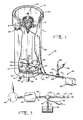
- the flotation apparatus 10 can be noted to have a plurality of elements which may be grouped, for convenience, into a flotation cylinder, wherein an aqueous slurry of suspended mineral and gangue particles is separated into a float fraction and a non-float fraction, an aerated water distribution system, and an aerated water production subsystem.
- a flotation cylinder wherein an aqueous slurry of suspended mineral and gangue particles is separated into a float fraction and a non-float fraction, an aerated water distribution system, and an aerated water production subsystem.
- the flotation cylinder is formed as an upright circular cylinder having a vertical wall 11 and a bottom wall 12.
- the flotation cylinder is typically open at an upper end 13 thereof.
- Both the flotation compartment 17 and the hydraulic compartment 18 are adapted to contain relatively quiescent bodies of liquid, with the orifices 16 in the constriction plate 14 serving as communicating passages between the hydraulic compartment 18 and the flotation compartment 17.
- a pulp feed well 19 is supported substantially centrally within the upper end portion 13 of the flotation compartment 17.
- a feed tube 20, from an external source of aqueous slurry, is generally provided to deliver a controllable quantity of the aqueous slurry to the feed well 19.
- the feed well 19 has a plurality of apertures 21 therethrough, which may include baffles (not illustrated) such that the aqueous slurry fed into the feed well 19 becomes distributed throughout the flotation compartment 17.
- the hydraulic compartment 18 contains a relatively quiescent body of aerated water which is substantially uniformly distributed throughout the volume of the hydraulic compartment 18 by a distribution manifold 22. Details of the preferred embodiment of the distribution manifold will be set forth below.
- the introduction of a flow of aerated water into the hydraulic compartment 18 through the distribution manifold 22 tends to produce a higher static pressure of the aerated water within the hydraulic compartment 18 than that obtained within the body of aqueous slurry within the flotation compartment 17 immediately above the constriction plate 14.
- This difference in static pressure causes a portion of the aerated water contained in the hydraulic compartment 18 to flow upwardly through the orifices 16 in the constriction plate 14, thereby inhibiting any downward flow of aqueous slurry, or the particulate matter suspended therein, through said orifices 16 into the hydraulic compartment 18.
- An aerated water feed line 23 enters the hydraulic compartment 18 through the cylinder wall 11 and conveys aerated water from the production subsystem to the distibution manifold 22.
- the aerated water within the compartment 18 contains a multitude of minute air bubbles which levitate through the aqueous slurry within the flotation compartment 17.
- an appropriate one of a number of known reagents commonly known as surfactants or frothers
- either the particles of the desired valuable mineral or the particles of gangue suspended in the aqueous slurry are captured, as a float fraction, by the rising air bubbles and carried to the surface at the upper end 13 of the flotation compartment 17 in the form of a froth.
- An overflow launder 24 is affixed annularly to the upper end 13 of the cylinder wall 11 into which the resulting froth overflows from the flotation compartment 17.
- An output conduit 26 is provided to convey the overflowing froth from the launder 24 to further processing or storage apparatus external to the flotation apparatus 10.
- the constriction plate 14 has a downwardly concave upper surface 27.
- the continued gravitation of the solid non-float fraction particles therefore continues along the upper surface 27 of the constriction plate 14 until the lowest portion thereof, disposed substantially centrally of the cylinder, is reached. It is to be re-emphasized that the upward flow of aerated water through the orifices 16 in the constriction plate 14 inhibits such particles from gravitating downwardly through the orifices 16.
- a hole 28 is formed through the constriction plate 14 at its central area into which the gravitating non-float fraction may enter.
- An underflow duct 29 is rigidly affixed to the rim of the hole 28 and depends therefrom to sealably pass through the bottom wall 12 of the cylinder.
- a valve (not illustrated) may be incorporated at the lower end of the underflow duct 29 to control the outflow of water and non-float fraction of the aqueous pulp. It is contemplated that in the flotation apparatus in accordance with the present invention, the valve controlling the outflow through the underflow duct 29 need be opened only as required to remove the non-float fraction, since no continuous liquid flow is necessary. Additionally, cleaning entry ports 30 may be incorporated in the bottom wall 12 of the cylinder to enable cleaning of the hydraulic compartment 18 from time to time.
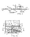
- the aerated water feed line 23 upon entering the hydraulic compartment 18 through the cylinder wall 11, is coupled to a distribution chamber 31.
- the distribution chamber 31 annularly surrounds the underflow duct 29 and may be formed as a pair of half cylinders coupled together by a flange 32 to form an annular enclosure around the circumference of the underflow duct 29.
- the aerated water feed line 23 enters the chamber 31 at its lower portion in a location substantially tangential to the outer wall of the underflow duct 29 so that the aerated water will circulate through the chamber 31.
- a plurality of distribution pipes extend outwardly from the upper portion of the distribution chamber 31 in a manner providing for introduction of aerated water into the hydraulic compartment 18 below the constriction plate 14 at a plurality of horizontally spaced positions.
- two sets of distribution pipes are utilized.
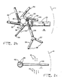
- a plurality of distribution pipes of a first type 33 extend substantially tangentially outwardly in a horizontal plane from the uppermost portion of the distribution chamber 31, each terminating in an upwardly directed nozzle 34.
- the plurality of nozzles 34 are located substantially equiangularly about a horizontal circle having a diameter substantially half that of the hydraulic compartment 18.
- six distribution pipes of the first type 33 having nozzles 34 are utilized, although any convenient number may be incorporated so as to evenly distribute the aerated water.
- a like plurality of distribution pipes of a second type 36 are disposed to extend substantially tangentially outward from the distribution chamber 31 at a vertical elevation on the distribution chamber 31 below that at which the distribution pipes of the first type 33 are disposed and above that at which the aerated water feed line 23 enters the distribution chamber 31.
- Each of the distribution pipes of the second type 36 branch through an outwardly extending Y extension into two arms 37 and 38, each terminating in an upwardly directed nozzle 39.
- the lengths of the arms 37 and 38 are adapted such that the nozzles 39 are substantially equiangularly spaced about a horizontal circle having a radius approximately eighty percent (80%) of the radius of the hydraulic compartment 18.
- the substantially tangential coupling of the aerated water feed line 23 to the distribution chamber 31 tends to cause the aerated water entering the chamber 31 to circulate in a substantially clockwise annular flow when viewed from the top.
- the substantially tangential coupling of the distribution pipes of the first type and the second type 36 to the distribution chamber 31 provides that such clockwise annular flow will tend to be introduced into each of the distribution pipes 33 and 36 in approximately equal amounts.
- three additional nozzles 40 are coupled to an upper face 41 of the distribution chamber 31 to provide for distribution of aerated water in the central portion of the hydraulic compartment 18 surrounding the underflow duct 29.
- the nozzles 40 may be canted with respect to a vertical axis so that the aforesaid clockwise annular flow aerated water within the distribution chamber 31 may more readily enter said nozzles 40.
- an auxiliary aerated water distribution cylinder 42 may be incorporated within the lower portion of the flotation compartment 17.
- the cylinder 42 has a horizontal diameter approximately equal to but greater than the diameter of the hole 28.
- the cylinder 42 is provided with a supply of aerated water by a secondary aerated water feed line 44 entering through the cylinder wall 11 from a coupling with the aerated water feed line 23 external of the cylinder of the flotation apparatus 10.
- the cylinder 42 is provided with a plurality of upwardly directed apertures 46 adapted to provide a distribution of levitating air bubbles within the aforesaid portion of the flotation compartment 17 disposed vertically over the hole 28 in the constriction plate 14.
- the aerated water feed line 23 may include a further branch 48 external of the cylinder of the flotation apparatus 10, which branch 48 may be directed to the feed well 19 near the top of the flotation compartment 17.
- the supply of aerated water to the feed well 19 in this manner is well understood and is described more fully in U.S. Patent No. 4,394,258.
- an isolated shematic representation of the aerated water production subsystem illustrated the interrelationships of the several components forming such a subsystem.
- the primary flow medium is compressed air, nominallyly at a pressure of approximately twenty pounds per square inch.
- Atmospheric air is compressed in a compressor 49 of a known, typically electric, type and the compressed air may then be stored in an accumulator or reservoir 50.
- An enclosed air flow passage typically in the form of a tube 51, directs the compressed air from the reservoir 50 through a flow controlling valve 52 to an eductor 53.
- the tube 51 is, in the preferred embodiment, formed of appropriately coupled pipe segments having a nominal diameter of from one or six inches, dependent upon cell size, with lengths commensurate to the particular installation of the apparatus 10, a diameter of about one inch for a cell of thirty inches, two inches for a cell of five and one-half feet, and three inches for a cell of eight feet.
- the compressed air flows past an aspirating opening (not illustrated) to which an input water line 54, also having a nominal six inch diameter, is attached.
- Input water nominally at atmospheric pressure, is drawn by aspiration induced by the air flowing through the eductor 53 past the opening, into the input line 54 from an external water source 56.
- the input water line 54 may include a valve 57 to control the water flow, as necessary.
- a quantity of a desired surfactant or frother may be flowingly introduced into the water at a controllable rate through a valve port 58 so as to enter and mix with the flowing aspirated water in the input water line 54.
- the flowing air, aspirated water and the surfactant are then passed through a venturi region 59 of the eductor 53 in which the flow rate and pressure relationship common to venturi-type devices are employed to turbulently combine the air into the aspirated water and, if present, surfactant so as to form a multitude of small bubbles in the aerated water.
- the aerated water is then conveyed via a pipe 60, through a valve 61, to the aerated water feed line 23 for delivery to the distribution manifold 22 (FIG. 2a) and elsewhere as previously described.
- the preferred embodiment incorporates a parallel arrangement of two eductors 53, such that the air from the reservoir 50 flows through the tube 51 which branches into two tubes, each containing a valve 52, an eductor 53, and a flow control valve 61, before again uniting to form the aerated water feed line 23.
- the input water line 54 is branched into a pair of parallel lines through valves 57 to enter each eductor 53, respectively. This arrangement is illustrated in FIG. 6.
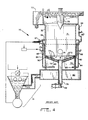
- the flotation apparaus 70 comprises a flotation compartment 71 adapted to contain a body of aqueous pulp to be separated into float and nonfloat fractions, a hydraulic compartment 72 disposed directly below the flotation compartment 71 and adapted to contain a body of aerated water that is introduced to the flotation compartment through orifices 73 formed in a constriction plate 74 which as the bottom wall of the flotation compartment 71.
- An apertured pulp feed well 76 is provided adjacent to an upper end of the apparatus for introducing an aqueous pulp into the flotation compartment 71.
- An annular frother overflow launder 77 is provided adjacent to the upper end of the flotation compartment 71 for withdrawing the float fraction therefrom.
- a low velocity underflow discharge duct 78 is provided adjacent to the lower end of the flotation compartment 71 for withdrawing underflow or non-float material from the flotation compartment 71.
- the flotation compartment 71 and the hydraulic compartment 72 are contained within a common cylindrical wall 75.
- a second constriction plate 79 having a similar set of orifices 73, is spaced below and extends parallel to the constriction plate 74 so as to form a volume therebetween.
- a water collecting or recovery compartment 80 is disposed beneath the hydraulic compartment 72.
- a plurality of apertures are provided to enable fluid communication between the collecting compartment 80 and the hydraulic compartment 72.
- the undeflow discharge duct 78 is substantially centered and is sealingly secured at its upper end to an opening 81 through the constriction plate 74.
- constriction plate 79, the interface between the hydraulic compartment 72 and the collecting compartment 80, and the bottom wall of the apparatus are sealingly secured to the outer periphery of duct 78.
- a valve 82 is disposed for movement within the lower end of the duct 78 to control the rate of discharge of water and non-float fraction from the flotation compartment 71.
- the hydraulic compartment 72 Since the hydraulic compartment 72 should, for proper operation of the flotation apparatus 70, contain a uniformly aerated body of water maintained at a slightly higher static pressure than that of the aqueous pulp in the flotation compartment 71, the hydraulic compartment 72 is provided with a plurality of radially inwardly directed aerated water feed pipes 83 of several differing lengths introducing aerated water thereinto. These pipes 83 are externally connected to pipes 84 leading to an annular water manifold 86 having a fitting 87 to which water at a pressure of, for example, twenty-five to fifty pounds per square inch is connected. In series with each of the pipes 84 is a conventional aspirator 88. Such aspirators, serving to introduce air into the flowing water, may be the same as that shown and described in U.S. Patent No. 3,371,779.
- Another pipe 89 may be connected at one end to the manifold 86 and at the other end to the feed well 76.
- An aspirator 88 is connected in series with the pipe 89.
- a further plurality of pipes 90, without aspirators, are directed from the annular manifold 86 radially into the aforesaid volume between the constriction plates 74 and 79 and serve to provide additional static pressure in said volume. This added water, known as seal water, aids in precluding the downward migration of non-float fraction particles through the orifices 73.
- water In order to minimize the quantity of additional water necessary during operation of the flotation apparatus 70, water, generally free of aeration, migrates downwardly from the hydraulic compartment 72 through the apertures into the collecting compartment 80 from whence water is recirculated through a pumping system 91 to the fitting 87 on the annular manifold 86. "New" water is added at the pumping system 91 as may be necessary to replace that leaving the system through the overflow launder 77 and the underflow duct 78.
- an example of an alternate approach to the production of aerated water for use in the previously described flotation apparatus 70 utilizes one or more parallelly disposed eductors 92, disposed external to the flotation compartment 71 of FIG. 4.
- Water comprising an appropriate combination of recirculating water 93, withdrawn from the collecting compartment 80, and new water 94, added from a source external to the system, is delivered by a pump 96 at a substantially high flow rate, typically of the order of one thousand gallons per minute or greater, to each eductor 92.
- an appropriate quantity of one of the usual surfactants, frothers, or other flotation reagents may be introduced to the water flow through an injection device 97 disposed at a point in the flow path subsequent to the pump 96 but before the eductor 92.
- an injection device 97 disposed at a point in the flow path subsequent to the pump 96 but before the eductor 92.
- atmospheric air 98 is aspirated by water flowing through the eductor 92, the air entering through appropriate ports 99.
- a valve 100 and a valve 101 may be incorporated to control the water and air flow rates, respectively.
- an aqueous slurry fed thereto is typically of a high water concentration, wherein the solid particulate matter, consisting of both the float and non-float fractions, is generally of the order of ten percent (10%) by volume.
- the addition of quantitites of water, as is typical of prior known systems, will substantially further reduce the solid matter concentration.
- the present invention significantly reduces the loss of valuable minerals in the above stated manner by limiting the quantity of water introduced to the flotation compartment 17 to that aspirated at the eductor 53 and transported as aerated water therefrom to the flotation compartment 17.
- the water flow rate will be approximately one hundred gallons per minute, which is roughly equivalent to the rate of removal of the float fraction through the overflow launder 24, disposed at the top of the flotation compartment 17.
- the rate of flow of air into the eductor 53 may be varied over a significant range of flow rates without significantly altering the flow rate of the water into the eductor 53 and thence into the flotation compartment 17.
- the concentration of air bubbles in the aerated water emanating from the eductor 53 may be closely controlled by varying the flow rate of aerated water varying only slightly in response to a change in the air flow rate.
- the valve 61 may be adjusted appropriately to further control the flow rate of aerated water to the flotation compartment 17.
- Such gangue particles are thus diverted from their downward paths so as to reach the constriction plate 16 at regions adjacent the orifices 16 whereat they will tend to migrate to the hole 28 and thence into the underflow duct 29 for removal from the system. Since the underflow duct 29 is not primarily required for the withdrawal of excess water, as may be necessary in the high water flow rate systems previously known, the removal of gangue may be accomplished on an "as required" rather than continuous basis. Additionally, should any gangue particles inadvertently gravitate downwardly through the orifices 16 in the constriction plate 14, they will not be drawn from the hydraulic chamber 18 since no recirculation of water is contemplated.
- the volumes of water necessary to be moved and aerated through prior known systems typically are at a rate exceeding twleve hundred gallons per minute, requiring the expenditure of significant energy through motors driving the pumps associated with moving the water, while in the flotation apparatus of the present invention, the energy input required is limited to that necessary to drive the air compressor 49.
- an experimental system in accordance with the present invention modified from an existing system of the type described in U.S. Patent No.
- the air compressor is operated by an electric motor rated at twenty-five horsepower, whereas the electric motor driving the pump of the prior system typically required in excess of sixty horsepower to provide an essentially identical flow of air bubbles through the flotation chamber.
- a flotation apparatus in accordance with the present invention has utilized, as an example, the flotation separation of an aqueous slurry containing nominally ten percent particulate matter by volume, as exemplified by sulfides, the apparatus will function as described for the efficient separation of slurries having a solid particulate concentration of approximately twenty-five percent or greater, by volume, which is within the range of slurries encompassing coal.
- Aqueous slurries having higher volumetric densities of particulate matter, such as the phosphates, in which the solid particles form nominally seventy-five percent of the volume may be subjected to flotation separation by the apparatus of the present invention by merely diluting the pulp with additional water to bring the slurry within the volumetric density range set forth herein, such dilution occurring prior to feeding the pulp to the flotation compartment.
Landscapes
- Life Sciences & Earth Sciences (AREA)
- Engineering & Computer Science (AREA)
- Biotechnology (AREA)
- Paper (AREA)
Applications Claiming Priority (2)
| Application Number | Priority Date | Filing Date | Title |
|---|---|---|---|
| US752465 | 1985-07-05 | ||
| US06/752,465 US4639313A (en) | 1985-07-05 | 1985-07-05 | Floatation apparatus for concentration of minerals from high water content aqueous slurries |
Publications (2)
| Publication Number | Publication Date |
|---|---|
| EP0208411A2 true EP0208411A2 (de) | 1987-01-14 |
| EP0208411A3 EP0208411A3 (de) | 1987-12-02 |
Family
ID=25026440
Family Applications (1)
| Application Number | Title | Priority Date | Filing Date |
|---|---|---|---|
| EP86304261A Withdrawn EP0208411A3 (de) | 1985-07-05 | 1986-06-04 | Vorrichtung zur Trennung von Mineralien aus einer wässerigen Trübe durch Schaumflotation |
Country Status (8)
| Country | Link |
|---|---|
| US (1) | US4639313A (de) |
| EP (1) | EP0208411A3 (de) |
| AU (1) | AU580498B2 (de) |
| CA (1) | CA1252232A (de) |
| ES (1) | ES8707303A1 (de) |
| FI (1) | FI862485A7 (de) |
| PH (1) | PH22865A (de) |
| ZA (1) | ZA863974B (de) |
Cited By (6)
| Publication number | Priority date | Publication date | Assignee | Title |
|---|---|---|---|---|
| EP0275626A3 (de) * | 1987-01-21 | 1988-10-05 | The Deister Concentrator Co., Inc. | Verfahren zur Mineralabtrennung durch Schaumflotation |
| CN109794361A (zh) * | 2019-03-12 | 2019-05-24 | 广州市丹爵通讯科技有限公司 | 一种用于有色金属选矿的便于收集的浮选设备 |
| CN111375495A (zh) * | 2020-03-23 | 2020-07-07 | 合肥市恒昌自动化控制有限责任公司 | 一种智能浮选加药装置 |
| CN111389600A (zh) * | 2020-03-23 | 2020-07-10 | 合肥市恒昌自动化控制有限责任公司 | 一种智能浮选加药系统 |
| CN113318866A (zh) * | 2021-06-01 | 2021-08-31 | 合肥皖燃新材料科技有限公司 | 高白超细型物理法氢氧化镁阻燃剂及其制备方法 |
| CN114700182A (zh) * | 2021-07-22 | 2022-07-05 | 中国矿业大学 | 一种梯度进气的粗颗粒流态化浮选装置及方法 |
Families Citing this family (29)
| Publication number | Priority date | Publication date | Assignee | Title |
|---|---|---|---|---|
| US4822493A (en) * | 1987-11-27 | 1989-04-18 | Universite Laval, Cite Universitaire | Method for separation of coarse particules |
| US5167375A (en) * | 1988-04-04 | 1992-12-01 | Datta Rabinder S | Apparatus for mineral matter separation |
| US4964576A (en) * | 1988-04-04 | 1990-10-23 | Datta Rabinder S | Method and apparatus for mineral matter separation |
| FI79953C (fi) * | 1988-04-28 | 1990-04-10 | Svi Distec Oy | Apparatur foer flotationsanrikning. |
| US5078921A (en) * | 1988-10-21 | 1992-01-07 | The Deister Concentrator Company, Inc. | Froth flotation apparatus |
| US5116487A (en) * | 1990-07-27 | 1992-05-26 | University Of Kentucky Research Foundation | Froth flotation method for recovery of ultra-fine constituent |
| US5341938A (en) * | 1991-03-20 | 1994-08-30 | Servicios Corporativos Frisco, S.A. De C.V. | Method of separating materials in a flotation reactor |
| US5234112A (en) * | 1991-10-02 | 1993-08-10 | Servicios Corporativos Frisco S.A. De C.V. | Flotation reactor with external bubble generator |
| US5266240A (en) * | 1991-03-20 | 1993-11-30 | Servicios Corporativos Frisco, S.A. De C.V. | Flotation reactor with external bubble generator |
| JP2872829B2 (ja) * | 1991-07-31 | 1999-03-24 | オルガノ株式会社 | 超純水の製造のための曝気装置及び方法 |
| SE503894C2 (sv) * | 1995-01-19 | 1996-09-30 | Norrtaelje Kommun | Anordning för distribution och dispersion av luftmättat vatten |
| US5670093A (en) * | 1996-02-14 | 1997-09-23 | Atlantic Richfield Company | Fluid distribution system and method utilizing a radial splitter |
| US7510083B2 (en) * | 2004-06-28 | 2009-03-31 | The Mosaic Company | Column flotation cell for enhanced recovery of minerals such as phosphates by froth flotation |
| US20070012597A1 (en) * | 2005-07-13 | 2007-01-18 | Crystal Filtration Company | Process and apparatus for filtering metal working fluid containing metal fines |
| US7537674B1 (en) | 2006-06-12 | 2009-05-26 | Narayanasamy Seenivasan | Closed floatation de-inking module for recycled paper |
| US7544271B1 (en) | 2006-06-12 | 2009-06-09 | Narayanasamy Seenivasan | Open flotation de-inking module for recycled paper |
| US7562777B1 (en) | 2006-06-12 | 2009-07-21 | Narayanasamy Seenivasan | Flotation cell injector assembly for use with open or closed flotation deinking modules for recycled paper |
| CA2676776C (en) | 2007-04-12 | 2015-03-31 | Eriez Manufacturing Company | Flotation separation device and method |
| CN102847613B (zh) * | 2012-09-25 | 2015-05-06 | 北矿机电科技有限责任公司 | 一种浮选柱 |
| CN103386372B (zh) * | 2013-08-08 | 2015-03-11 | 中冶北方(大连)工程技术有限公司 | 浮选机底部加药装置 |
| CN109310958B (zh) * | 2016-06-15 | 2021-12-14 | 安斋聪 | 养殖用或排水处理用超微细气泡产生装置 |
| CN109746113B (zh) * | 2018-12-28 | 2021-03-02 | 河南科技大学 | 一种颗粒物料水选装置 |
| CN109772594B (zh) * | 2019-02-25 | 2021-10-12 | 郑州大学 | 一种强剪切脉冲气流成泡的控制系统 |
| CN113198622B (zh) * | 2021-05-18 | 2022-02-11 | 中南大学 | 一种微泡二次矿化浮选设备及浮选方法 |
| CN114345210B (zh) * | 2022-01-10 | 2024-06-11 | 三河市来金涂料工程有限公司 | 一体化水性涂料生产装置 |
| EP4743229A1 (de) * | 2023-07-14 | 2026-05-20 | Metso Finland Oy | Versorgungsanordnung für vergastes fluid und flotationszelle |
| FI20235824A1 (en) * | 2023-07-14 | 2025-01-15 | Metso Finland Oy | Feeding arrangement for gasified liquid and flotation cell |
| CN116851132A (zh) * | 2023-07-27 | 2023-10-10 | 中国矿业大学 | 一种基于流态化浮选机的粗颗粒煤泥回收系统及工艺 |
| CN117380381B (zh) * | 2023-11-16 | 2026-07-03 | 西北矿冶研究院 | 一种提高氧化锌精选作业效率的方法 |
Family Cites Families (10)
| Publication number | Priority date | Publication date | Assignee | Title |
|---|---|---|---|---|
| US1598858A (en) * | 1923-04-02 | 1926-09-07 | William E Greenawalt | Apparatus for treating liquids with gases |
| US2883167A (en) * | 1954-06-05 | 1959-04-21 | Svenska Flaektfabriken Ab | Apparatus for supplying and mixing a liquid into a gaseous medium |
| US2883169A (en) * | 1955-04-29 | 1959-04-21 | Mining Process & Patent Co | Aerating apparatus for flotation pulps |
| US3371779A (en) * | 1965-06-24 | 1968-03-05 | Borden Co | Concentration of minerals |
| US3642617A (en) * | 1970-01-29 | 1972-02-15 | Fmc Corp | Foam flotation concentrator |
| US4054619A (en) * | 1974-02-22 | 1977-10-18 | Coverston George C | Atomizing and mixing apparatus |
| US4287054A (en) * | 1980-05-05 | 1981-09-01 | The Deister Concentrator Co., Inc. | Flotation apparatus for concentration of minerals |
| US4328107A (en) * | 1980-11-28 | 1982-05-04 | Synergo, Inc. | Process and apparatus for forming dispersions |
| US4431531A (en) * | 1981-06-08 | 1984-02-14 | The Deister Concentrator Company, Inc. | Concentration of minerals by flotation apparatus |
| US4394258A (en) * | 1981-06-25 | 1983-07-19 | The Diester Concentrator Co., Inc. | Froth flotation apparatus with water recovery and method |
-
1985
- 1985-07-05 US US06/752,465 patent/US4639313A/en not_active Expired - Fee Related
-
1986
- 1986-05-13 CA CA000508979A patent/CA1252232A/en not_active Expired
- 1986-05-28 ZA ZA863974A patent/ZA863974B/xx unknown
- 1986-06-04 EP EP86304261A patent/EP0208411A3/de not_active Withdrawn
- 1986-06-11 AU AU58551/86A patent/AU580498B2/en not_active Withdrawn - After Issue
- 1986-06-11 FI FI862485A patent/FI862485A7/fi not_active Application Discontinuation
- 1986-06-17 ES ES556139A patent/ES8707303A1/es not_active Expired
- 1986-06-30 PH PH33968A patent/PH22865A/en unknown
Cited By (10)
| Publication number | Priority date | Publication date | Assignee | Title |
|---|---|---|---|---|
| EP0275626A3 (de) * | 1987-01-21 | 1988-10-05 | The Deister Concentrator Co., Inc. | Verfahren zur Mineralabtrennung durch Schaumflotation |
| CN109794361A (zh) * | 2019-03-12 | 2019-05-24 | 广州市丹爵通讯科技有限公司 | 一种用于有色金属选矿的便于收集的浮选设备 |
| CN109794361B (zh) * | 2019-03-12 | 2020-12-29 | 烟台市瑞凯环保材料有限公司 | 一种用于有色金属选矿的便于收集的浮选设备 |
| CN111375495A (zh) * | 2020-03-23 | 2020-07-07 | 合肥市恒昌自动化控制有限责任公司 | 一种智能浮选加药装置 |
| CN111389600A (zh) * | 2020-03-23 | 2020-07-10 | 合肥市恒昌自动化控制有限责任公司 | 一种智能浮选加药系统 |
| CN111375495B (zh) * | 2020-03-23 | 2021-11-26 | 合肥市恒昌自动化控制有限责任公司 | 一种智能浮选加药装置 |
| CN111389600B (zh) * | 2020-03-23 | 2021-11-30 | 合肥市恒昌自动化控制有限责任公司 | 一种智能浮选加药系统 |
| CN113318866A (zh) * | 2021-06-01 | 2021-08-31 | 合肥皖燃新材料科技有限公司 | 高白超细型物理法氢氧化镁阻燃剂及其制备方法 |
| CN113318866B (zh) * | 2021-06-01 | 2023-02-10 | 合肥皖燃新材料科技有限公司 | 高白超细型物理法氢氧化镁阻燃剂加工用曝气式浮选机 |
| CN114700182A (zh) * | 2021-07-22 | 2022-07-05 | 中国矿业大学 | 一种梯度进气的粗颗粒流态化浮选装置及方法 |
Also Published As
| Publication number | Publication date |
|---|---|
| ES8707303A1 (es) | 1987-07-16 |
| ZA863974B (en) | 1987-01-28 |
| EP0208411A3 (de) | 1987-12-02 |
| FI862485A0 (fi) | 1986-06-11 |
| ES556139A0 (es) | 1987-07-16 |
| US4639313A (en) | 1987-01-27 |
| FI862485A7 (fi) | 1987-01-06 |
| AU580498B2 (en) | 1989-01-12 |
| PH22865A (en) | 1989-01-19 |
| AU5855186A (en) | 1987-01-08 |
| CA1252232A (en) | 1989-04-04 |
Similar Documents
| Publication | Publication Date | Title |
|---|---|---|
| US4639313A (en) | Floatation apparatus for concentration of minerals from high water content aqueous slurries | |
| US4735709A (en) | Method and apparatus for concentration of minerals by froth flotation using dual aeration | |
| US3371779A (en) | Concentration of minerals | |
| US3400818A (en) | Froth flotation | |
| US5397001A (en) | Apparatus for the separation of hydrophobic and hydrophilic particles using microbubble column flotation together with a process and apparatus for generation of microbubbles | |
| US4287054A (en) | Flotation apparatus for concentration of minerals | |
| FI122471B (fi) | Menetelmä ja laitteisto vaahdotusta varten leijupetissä | |
| US4431531A (en) | Concentration of minerals by flotation apparatus | |
| US5814210A (en) | Apparatus and process for the separation of hydrophobic and hydrophilic particles using microbubble column flotation together with a process and apparatus for generation of microbubbles | |
| US3428175A (en) | Process and apparatus for froth flotation | |
| US7624877B2 (en) | Separate size flotation device | |
| CN1310260A (zh) | 用于进行充气分散的方法和设备 | |
| US4394258A (en) | Froth flotation apparatus with water recovery and method | |
| US4220612A (en) | Flotation cell feed duct | |
| WO2000015343A1 (en) | Internal recycle apparatus and process for flotation column cells | |
| US5591328A (en) | Gas particle formation | |
| US4613431A (en) | Froth flotation separation apparatus | |
| US4450072A (en) | Air flotation cell | |
| US5762781A (en) | Flotation apparatus and process | |
| EP0364654A2 (de) | Verfahren und Vorrichtung zur Erzeugung von Mikroblasen in Schaumflotation-Mineralaufbereitungssystemen | |
| FI79953B (fi) | Apparatur foer flotationsanrikning. | |
| US4613430A (en) | Froth flotation separation method and apparatus | |
| US20250121308A1 (en) | In-line air separator and fluid deceleration method and apparatus | |
| CN223393604U (zh) | 浆料供给装置和浮选池 | |
| CN113304890A (zh) | 一种强化矿化气泡与矿浆离析的射流微泡浮选机 |
Legal Events
| Date | Code | Title | Description |
|---|---|---|---|
| PUAI | Public reference made under article 153(3) epc to a published international application that has entered the european phase |
Free format text: ORIGINAL CODE: 0009012 |
|
| AK | Designated contracting states |
Kind code of ref document: A2 Designated state(s): DE FR GB IT SE |
|
| PUAL | Search report despatched |
Free format text: ORIGINAL CODE: 0009013 |
|
| AK | Designated contracting states |
Kind code of ref document: A3 Designated state(s): DE FR GB IT SE |
|
| 17P | Request for examination filed |
Effective date: 19880215 |
|
| 17Q | First examination report despatched |
Effective date: 19890428 |
|
| STAA | Information on the status of an ep patent application or granted ep patent |
Free format text: STATUS: THE APPLICATION IS DEEMED TO BE WITHDRAWN |
|
| 18D | Application deemed to be withdrawn |
Effective date: 19910129 |
|
| RIN1 | Information on inventor provided before grant (corrected) |
Inventor name: ZIPPERIAN, DONALD E. |