EP0208445A2 - Rückblickspiegel - Google Patents
Rückblickspiegel Download PDFInfo
- Publication number
- EP0208445A2 EP0208445A2 EP86304746A EP86304746A EP0208445A2 EP 0208445 A2 EP0208445 A2 EP 0208445A2 EP 86304746 A EP86304746 A EP 86304746A EP 86304746 A EP86304746 A EP 86304746A EP 0208445 A2 EP0208445 A2 EP 0208445A2
- Authority
- EP
- European Patent Office
- Prior art keywords
- rear view
- view mirror
- mirror according
- casing
- toothed wheel
- Prior art date
- Legal status (The legal status is an assumption and is not a legal conclusion. Google has not performed a legal analysis and makes no representation as to the accuracy of the status listed.)
- Withdrawn
Links
Images



Classifications
-
- B—PERFORMING OPERATIONS; TRANSPORTING
- B60—VEHICLES IN GENERAL
- B60R—VEHICLES, VEHICLE FITTINGS, OR VEHICLE PARTS, NOT OTHERWISE PROVIDED FOR
- B60R1/00—Optical viewing arrangements; Real-time viewing arrangements for drivers or passengers using optical image capturing systems, e.g. cameras or video systems specially adapted for use in or on vehicles
- B60R1/02—Rear-view mirror arrangements
- B60R1/08—Rear-view mirror arrangements involving special optical features, e.g. avoiding blind spots, e.g. convex mirrors; Side-by-side associations of rear-view and other mirrors
- B60R1/083—Anti-glare mirrors, e.g. "day-night" mirrors
- B60R1/086—Anti-glare mirrors, e.g. "day-night" mirrors using a mirror angularly movable between a position of use and a non-glare position reflecting a dark field to the user, e.g. situated behind a transparent glass used as low-reflecting surface; Wedge-shaped mirrors
- B60R1/087—Anti-glare mirrors, e.g. "day-night" mirrors using a mirror angularly movable between a position of use and a non-glare position reflecting a dark field to the user, e.g. situated behind a transparent glass used as low-reflecting surface; Wedge-shaped mirrors with remote or automatic control means
Definitions
- This invention relates to a rear view mirror for vehicles with an adjustable mirror surface to prevent the effects of glare.
- Rear view mirrors with a mirror surface which is automatically adjusted by an electric motor in conditions of incresed light intensity have become known in various embodiments.
- the' embodiments known so far have certain drawbacks with regard to practical use. In particular it appeared that relatively strong motors were required and these created excessive noise.
- the previous automatic rear view mirrors could not be manufactured at a suitable price.
- the object of the present invention is therefore to improve a rear view mirror as described in the introduction in such a way that it is inexpensive to manufacture, is largely maintenance-free and does not wear very easily, while the tilting movement is carried out quietly and within small spacial dimensions.
- the mirror surface is adjustably connected to an actuator which is engaged in a cam surface formation, the various profile heights of which correspond to various angles of adjustment in respect of the mirror.
- the intensity of the light falling on the mirror is measured by a photoelectric cell.
- the mirror is then adjusted in accordance with the determined light intensity over a predetermined light intensity threshold value in order to thus prevent the driver being dazzled.
- the adjusting movements are preferably carried out with the aid of a toothed wheel which carries the cam surface formation, and are transferred from an electric motor onto the actuator which is connected to a casing containing the mirror surface.
- the design of the cam formation ensures that the motor need only revolve in the same direction and all toothing of the drive is always engaged. Early wear and undesirable impacts inside the drive can thus be avoided.
- the dimensions of the electric motor can be relatively small as it only needs to produce the small amounts of power which are required to overcome bearing friction. Due to the structural design of the connection between the parts which are adjusted in respect of each other the elctric motor need to do hardly any lifting work.
- the light intensity threshold value which causes the rear view mirror to be adjusted can be regulated with the aid of an adjusting wheel.
- the rear view mirror can therefore be adjusted by drivers to suit various light intensity levels and sensitivities to light.
- the casing of the rear view mirror is designed in such a way that depending on purpose and availability various sizes of mirror glasses can be inserted into the casing.
- a rear view mirror essentially comprises a main casing 1, a mirror casing 3 containing a mirror surface 2 and also a bearing arm 4.
- the rear view mirror is fastened to a vehicle (not shown) by means of the bearing arm 4, and specifically above the windscreen within the vehicle.
- the bearing arm 4 is arranged in a recess 6 of casing 1.
- the casing 1 can thus be turned vis a vis the bearing arm 4 which is firmly fixed to the vehicle and can be adjusted according to the various heights and sitting positions of different drivers of the vehicle.
- the casing 3 is connected to an actuator 8 by means of coupling projections 7.
- the coupling projections 7 are rotatingly arranged in recesses 9 of the actuator 8.
- the actuator 8 has a further recess 10 into which a toothed wheel 11 engages.
- the toothed wheel 11 is rotatingly arranged in casing 1 and fastened in a guide 13 by means of threaded screw 12.
- the guide 13 is integral with the forward wall 14 of casing 1.
- a disk 17 is provided between the head 15 of the threaded screw 12 and the side surface 16 of the toothed wheel 11 extending parallel to the forward casing wall 14.
- the toothed wheel 11 engages in a helical thread 19 on the drive axle 20 of a motor 21. Whereby when the motor 21 is supplied with power through leads 22, the toothed wheel 11 rotates. The rotational plane 23 is thereby parallel to the forward casing wall 14.
- the toothed wheel 11 has a raised cam surface portion 26 in its outer area 25 relative to the axis of rotation 24.
- the cam portion 26 is such that the outer area zone 25 is the same size i.e. same height over the total circumference of the toothed wheel 11 measured normal from the plane of rotation 23.
- the surfaces 27, 28 Figs 10, 11 of the outer area zone 25 extending parallel to the plane of rotation 23 vary in distance 29, 30 from the forward casing wall 14 throughout the circumference of the toothed wheel 11 due to the design of the raised cam portion 26.
- the cam portion 26 is such that the outer area zone 25 for a quarter of its extent along the circumference of the toothed wheel 11 comprises surfaces 27, 28 at constant distances 29, 30 respectively from the forward parallel casing wall 14. In the remaining portion of outer area zone 25 the distance of the surfaces to the casing part 14 continually increases or decreases.
- the actuator 8 is guided by virtue of points 31 acting on the surfaces 27, 28 and the intermediate rising and falling surface parts. In addition the actuator 8 is further guided in a slit 32 in the casing wall 14. Due to the rotating movement of the toothed wheel 11 the actuator 8 is mvoed normally towards or away from the forward casing part 14 through the slit 32 in accordance with the course of the cam portion 26.
- casing 3 Due to the coupling 7, 9 of the casing 3 with the actuator 8, the casing 3 in the area of the coupling projections 7 is at varying distances from casing 1.
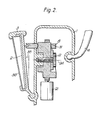
- casing 3 is adjustably guided in recesses 34 of the forward casing wall 14 by means of rounded coupling parts 33. Because of the geometric arrangement of the coupling parts 7, 33 a movement of the actuator 8 out of the casing 1 brought about as a result of rotation of the toothed wheel 11 causes the mirror surface 2 to be tilted, and the actuator 8 moving into the casing 1 results in the mirror surface 2 moving to a more vertical position. When the mirror surface 2 is in the normal position shown in fig. 2, the mirror surface 2 is at an angle to the casing wall 14.
- the mirror surface 2 extends parallel to the wall 14 with the cam portion 26 at a maximum distance 30 from the casing wall 14. If the mirror had previously been adjusted so that the driver could observe following traffic due to the mirror effect, the light failing on the mirror surface is now reflected onto an area of the vehicle roof. However, so that the driver is also able to obtain information about the following traffic when the mirror surfacd is in this position, a glass sheet 36 is additionally provided in casing 3. In contrast to the mirror surface 2 the glass sheet is adjusted at a fixed angle 37, which is equal to the maximum angle of adjust ment 35 between mirror surface 2 and casing wall 14.
- the glass sheet 36 is therefore at the same angle with respect to the casing wall 14 as the mirror surface 2 is in fig.. 2.
- the glass surface also has reflective properties either the intensively reflected light from the mirror surface 2 reaches the driver's eyes, or the driver can obtain information about the following traffic through the considerably weaker image reflected from the surface of the glass sheet 36 when the rear view mirror is in the adjusted position.
- Adjustment to the angle 35 is always useful whenever the driver is being dazzled by following traffic or when the sun is low in the sky behind the vehicle.
- the intense light falling on the rear view mirror in such conditions is measured by means of a photosensor 38 which is located in the casing 1 behind an aperture 39.
- the intensity of the light falling on the photosensor 38 can be regulated by means of a screen 40 provided with a slit 41.
- the slit 41 is formed in such a way that in an area 42 of its length it is adapted to the rounded shape of the aperture 39 but with a larger cross-section than the latter.
- the slit is formed in such a way that it tapers away from the area 42 to end in a point.
- the screen 40 is part of an adjusting wheel 44 which rotatably arranged in casing 1 and a section of the circumference 46 of which projects out of the casing 1 through an opening 45.
- Area 46 of the adjusting wheel 44 is knurled 47 which facilitates the driver to turn the adjusting wheel 44 and thereby regulate the amount of light falling on the photosensor 38.
- the knurling 47 significantly improves the transfer of force from the driver's finger to the adjusting wheel 44 compared with a smooth design of area 46.
- the adjusting wheel 44 also has notches 48.
- casing 1 has a stopper 49 which engages in the notches 48.
- the stopper 49 exerts a force on the adjusting wheel 44 which on the one hand opposes the turning force and on the other hand has a component which is directed towards the mid-point of wheel 44.
- the adjusting wheel 44 has a relief slit 50.
- the force component acting on the mid-point of the adjusting wheel elastically compresses the adjusting wheel 44 in the area of the relief slit 50 and therefore the adjusting wheel 44 can be turned past the stopper 49 and is nevertheless fixed in an adjustable position without the effects of external forces.
- the adjusting wheel has two cams 53. These cams 53 limit together with the stopper 49 the rotation of the adjusting wheel 44 in its end position. In one direction of rotation the end position is reached when area 42 of the screen slit 41 is over the aperture 39 allowing maximum light to pass through. In the other direction of rotation the end position is reached when screen 40 completely covers aperture 39. In the latter position a switching cam 51 on the adjusting wheel 44 switches off the power supply of a threshold switch 55 (see Fig. 12) via an alternating switch 52 and the rear mirror is returned to its resting position by means of lead 60.
- the alternating switch 52 is preferably a microswitch.
- the power supply can be provided by a vehicle battery 54 in which the power is taken from the circuit for the vehicle interior lighting. It is however also conceivable to provide a separate battery or accumulator which is preferably arranged in casing 1. The accumulator could for example be charged by means of solar cells.
- the light falling on the photosensor 38 affects the power into the threshold switch 55. Over a certain light intensity the power is so great.that the threshold switch 55 produces a control signal which is led via lead 57 and alternating switch 59 to a switch amplifier 56.
- the switch amplifier 56 processes this signal and controls a motor 21 via leads 22.
- the thus controlled motor 21 causes the toothed wheel 11 to rotate.
- the opposing forces produced by the motor 21 driving the toothed wheel 11 are transferred onto members 63 of casing 1 through pins 61 which project out of both casing shields 62 of motor 21.
- the pins 61 are located in recesses 64 of the members 63.
- the casing 65 of the motor 21 is adjacent to further members 66 of casing 1.
- the actuator 8 When the toothed wheel 11 rotates, the actuator 8 is pulled into casing 1. Due to the form of the recess 32 it is guided vertically to the forward casing wall 14. The toothed wheel 11 rotates until one of the switching cams 67 on the toothed wheel 11 switches over the switch 59. Switch 59 is now connected with lead 58.
- the switching cam 67 is arranged on the toothed wheel 11 in such a way that the motor power is interrupted when the drive points 31 of the actuator 8 are guided in the centre of area 25 of the toothed wheel 11 extending parallel to the forward casing wall at distance 30.
- the driver is now able to observe the traffic following him by means of the weak image reflected from the surface of the glass sheet 36.
- the threshold switch 55 When the intensity of the light falling on the rear view mirror decreases, the threshold switch 55 reverts to its original position below a certain light intensity. This causes a control signal to be produced on lead 58 which reaches the switch amplifier 56 via the alternating switch 59 which is still in its other position, and the switch amplifier controls the motor 21. Rotation of the toothed wheel 11 is continued and the actuator 8 is pushed out of the casing 1. Rotation of the toothed wheel 11 is interrupted when another switch cam 69 located on the toothed wheel 11 switches the alternating switch 59 back into its other position and thereby breaks the connection between lead 58 and switch amplifier 56.
- the driver can adopt the brightness, which causes the rear view mirror to tilt, to the external lighting conditions and his own sensitivity to light. If the surrounding lighting conditions are bright only very great light intensity should cause the rear view mirror to tilt. In conditions of darkness the mirror should tilt even in weaker light as otherwise a strong dazzle effect will occur.
- Both the casings 1 and 3 can be made either of metal of synthetic material and the bearing arm 4 also can be made of such materials. It would be possible to have the casings 1 and 3 combined in a single integral casing.
Landscapes
- Engineering & Computer Science (AREA)
- Multimedia (AREA)
- Mechanical Engineering (AREA)
- Rear-View Mirror Devices That Are Mounted On The Exterior Of The Vehicle (AREA)
- Optical Elements Other Than Lenses (AREA)
- Mounting And Adjusting Of Optical Elements (AREA)
Applications Claiming Priority (2)
| Application Number | Priority Date | Filing Date | Title |
|---|---|---|---|
| DE19853522204 DE3522204A1 (de) | 1985-06-21 | 1985-06-21 | Rueckspiegel |
| DE3522204 | 1985-06-21 |
Publications (2)
| Publication Number | Publication Date |
|---|---|
| EP0208445A2 true EP0208445A2 (de) | 1987-01-14 |
| EP0208445A3 EP0208445A3 (de) | 1988-03-30 |
Family
ID=6273815
Family Applications (1)
| Application Number | Title | Priority Date | Filing Date |
|---|---|---|---|
| EP86304746A Withdrawn EP0208445A3 (de) | 1985-06-21 | 1986-06-20 | Rückblickspiegel |
Country Status (6)
| Country | Link |
|---|---|
| US (1) | US4838650A (de) |
| EP (1) | EP0208445A3 (de) |
| JP (1) | JPS6250248A (de) |
| AU (1) | AU600668B2 (de) |
| CA (1) | CA1306128C (de) |
| DE (1) | DE3522204A1 (de) |
Cited By (5)
| Publication number | Priority date | Publication date | Assignee | Title |
|---|---|---|---|---|
| GB2204544A (en) * | 1987-04-23 | 1988-11-16 | Mittelhaeuser Bernhard | Remote control external rear view mirror for motor vehicles |
| EP0400589A3 (de) * | 1989-06-01 | 1991-09-25 | Hohe Kg | Abblendbarer Spiegel |
| EP0857719A1 (de) * | 1997-02-06 | 1998-08-12 | Hüls Aktiengesellschaft | Kontinuierliches Verfahren zur Herstellung von 4-Aminopiperidinen |
| EP1155911A3 (de) * | 2000-05-16 | 2006-01-18 | Donnelly Corporation | System vom Rückblickspiegel mit Speicher für Fahrzeug |
| FR2943013A1 (fr) * | 2009-03-16 | 2010-09-17 | Peugeot Citroen Automobiles Sa | Procede et systeme pour bloquer le demarrage d'un vehicule |
Families Citing this family (47)
| Publication number | Priority date | Publication date | Assignee | Title |
|---|---|---|---|---|
| DE3727033C1 (de) * | 1987-08-13 | 1988-10-06 | Brinckmann Frank | Vorrichtung zum Verschwenken eines Kraftfahrzeugspiegels aus einer Normalstellung in eine Abblendstellung |
| US4948242A (en) * | 1988-03-22 | 1990-08-14 | Donnelly Mirrors Limited | Vehicle rearview mirror assembly |
| US5148014A (en) * | 1990-08-10 | 1992-09-15 | Donnelly Corporation | Mirror system with remotely actuated continuously variable reflectant mirrors |
| US5122647A (en) * | 1990-08-10 | 1992-06-16 | Donnelly Corporation | Vehicular mirror system with remotely actuated continuously variable reflectance mirrors |
| US5193029A (en) * | 1991-11-19 | 1993-03-09 | Donnelly Corporation | Single sensor adaptive drive circuit for rearview mirror system |
| US6822563B2 (en) | 1997-09-22 | 2004-11-23 | Donnelly Corporation | Vehicle imaging system with accessory control |
| US5670935A (en) | 1993-02-26 | 1997-09-23 | Donnelly Corporation | Rearview vision system for vehicle including panoramic view |
| US5550677A (en) * | 1993-02-26 | 1996-08-27 | Donnelly Corporation | Automatic rearview mirror system using a photosensor array |
| US7339149B1 (en) | 1993-02-26 | 2008-03-04 | Donnelly Corporation | Vehicle headlight control using imaging sensor |
| US5877897A (en) | 1993-02-26 | 1999-03-02 | Donnelly Corporation | Automatic rearview mirror, vehicle lighting control and vehicle interior monitoring system using a photosensor array |
| US6891563B2 (en) | 1996-05-22 | 2005-05-10 | Donnelly Corporation | Vehicular vision system |
| IL117403A (en) | 1996-03-07 | 2000-06-29 | Rogozinksi Joseph | Systems for the prevention of traffic blinding |
| US7655894B2 (en) | 1996-03-25 | 2010-02-02 | Donnelly Corporation | Vehicular image sensing system |
| US5969870A (en) * | 1997-09-18 | 1999-10-19 | Anvik Corporation | Remotely adjustable, anti-glare vehicle mirror system |
| US7697027B2 (en) | 2001-07-31 | 2010-04-13 | Donnelly Corporation | Vehicular video system |
| US6882287B2 (en) | 2001-07-31 | 2005-04-19 | Donnelly Corporation | Automotive lane change aid |
| AU2003225228A1 (en) | 2002-05-03 | 2003-11-17 | Donnelly Corporation | Object detection system for vehicle |
| US7308341B2 (en) | 2003-10-14 | 2007-12-11 | Donnelly Corporation | Vehicle communication system |
| US7526103B2 (en) | 2004-04-15 | 2009-04-28 | Donnelly Corporation | Imaging system for vehicle |
| US7881496B2 (en) | 2004-09-30 | 2011-02-01 | Donnelly Corporation | Vision system for vehicle |
| US7720580B2 (en) | 2004-12-23 | 2010-05-18 | Donnelly Corporation | Object detection system for vehicle |
| WO2008024639A2 (en) | 2006-08-11 | 2008-02-28 | Donnelly Corporation | Automatic headlamp control system |
| EP3624086B1 (de) | 2007-01-25 | 2025-07-09 | Magna Electronics Inc. | Radarerfassungssystem für fahrzeug |
| US7914187B2 (en) | 2007-07-12 | 2011-03-29 | Magna Electronics Inc. | Automatic lighting system with adaptive alignment function |
| US8017898B2 (en) | 2007-08-17 | 2011-09-13 | Magna Electronics Inc. | Vehicular imaging system in an automatic headlamp control system |
| WO2009036176A1 (en) | 2007-09-11 | 2009-03-19 | Magna Electronics | Imaging system for vehicle |
| US8446470B2 (en) | 2007-10-04 | 2013-05-21 | Magna Electronics, Inc. | Combined RGB and IR imaging sensor |
| US20100020170A1 (en) | 2008-07-24 | 2010-01-28 | Higgins-Luthman Michael J | Vehicle Imaging System |
| US9126525B2 (en) | 2009-02-27 | 2015-09-08 | Magna Electronics Inc. | Alert system for vehicle |
| US8874317B2 (en) | 2009-07-27 | 2014-10-28 | Magna Electronics Inc. | Parking assist system |
| US9495876B2 (en) | 2009-07-27 | 2016-11-15 | Magna Electronics Inc. | Vehicular camera with on-board microcontroller |
| EP2473871B1 (de) | 2009-09-01 | 2015-03-11 | Magna Mirrors Of America, Inc. | Abbildungs- und anzeigesystem für fahrzeuge |
| US20110051268A1 (en) * | 2009-09-03 | 2011-03-03 | Patrick Martin | Blind spot mirror |
| EP2340966B1 (de) * | 2009-12-30 | 2013-12-25 | SMR Patents S.à.r.l. | Rückspiegel für ein Fahrzeug mit einem Antennenmodul und elektronisches Anzeigemodul |
| US8890955B2 (en) | 2010-02-10 | 2014-11-18 | Magna Mirrors Of America, Inc. | Adaptable wireless vehicle vision system based on wireless communication error |
| US9117123B2 (en) | 2010-07-05 | 2015-08-25 | Magna Electronics Inc. | Vehicular rear view camera display system with lifecheck function |
| WO2012075250A1 (en) | 2010-12-01 | 2012-06-07 | Magna Electronics Inc. | System and method of establishing a multi-camera image using pixel remapping |
| US9264672B2 (en) | 2010-12-22 | 2016-02-16 | Magna Mirrors Of America, Inc. | Vision display system for vehicle |
| US9085261B2 (en) | 2011-01-26 | 2015-07-21 | Magna Electronics Inc. | Rear vision system with trailer angle detection |
| WO2013016409A1 (en) | 2011-07-26 | 2013-01-31 | Magna Electronics Inc. | Vision system for vehicle |
| US9446713B2 (en) | 2012-09-26 | 2016-09-20 | Magna Electronics Inc. | Trailer angle detection system |
| US9558409B2 (en) | 2012-09-26 | 2017-01-31 | Magna Electronics Inc. | Vehicle vision system with trailer angle detection |
| US10160382B2 (en) | 2014-02-04 | 2018-12-25 | Magna Electronics Inc. | Trailer backup assist system |
| US9694752B2 (en) * | 2014-11-07 | 2017-07-04 | Gentex Corporation | Full display mirror actuator |
| US10875403B2 (en) | 2015-10-27 | 2020-12-29 | Magna Electronics Inc. | Vehicle vision system with enhanced night vision |
| US10132971B2 (en) | 2016-03-04 | 2018-11-20 | Magna Electronics Inc. | Vehicle camera with multiple spectral filters |
| CN111964003A (zh) * | 2020-07-15 | 2020-11-20 | 无锡市宜佳乐网络科技有限公司 | 一种防反光功能的内置转向灯 |
Family Cites Families (15)
| Publication number | Priority date | Publication date | Assignee | Title |
|---|---|---|---|---|
| DE7900784U1 (de) * | 1979-04-05 | Car Mate Mfg. Co. Ltd., Tokio | Zusatzinnenspiegel, insbesondere Abblendspiegel, für Kraftfahrzeuge | |
| US2964999A (en) * | 1953-12-31 | 1960-12-20 | Libbey Owens Ford Glass Co | Rear view mirror assembly |
| US3158076A (en) * | 1962-11-30 | 1964-11-24 | Frank G Back | Control device for zoom lens systems |
| US3722984A (en) * | 1971-06-29 | 1973-03-27 | Baldwin Co D H | Day-night mirror for vehicles |
| GB1422411A (en) * | 1973-01-12 | 1976-01-28 | Baldwin Co D H | Day-night rear view mirror assembly for vehicles |
| FR2334145A1 (fr) * | 1975-12-03 | 1977-07-01 | Peugeot | Dispositif de commande simultanee des retroviseurs d'un vehicule automobile |
| US4281898A (en) * | 1979-02-07 | 1981-08-04 | Murakami Kaimeido Co., Ltd. | Automatic antiglare rearview mirror |
| JPS5937396Y2 (ja) * | 1980-05-08 | 1984-10-17 | 株式会社東海理化電機製作所 | 自動車のアウタ−ミラ−の角度調整装置 |
| US4494420A (en) * | 1981-05-08 | 1985-01-22 | Koito Seisakusho Co., Ltd. | Rotary-to-linear converter mechanism for a remotely controlled rearview mirror tilting device or the like |
| US4443057A (en) * | 1981-06-01 | 1984-04-17 | Gentex Corporation | Automatic rearview mirror for automotive vehicles |
| DE3234157A1 (de) * | 1981-09-23 | 1983-03-31 | Anthony Gourock Renfrewshire Scotland Stewart | Rueckspiegel |
| DE3147281A1 (de) * | 1981-11-28 | 1983-06-09 | Stewart, Anthony, Gourock, Renfrewshire,Scotland | Rueckspiegel fuer kraftfahrzeuge |
| JPS58126246U (ja) * | 1982-02-19 | 1983-08-27 | 株式会社東海理化電機製作所 | 防眩ミラ−の傾動装置 |
| IT1169828B (it) * | 1983-09-15 | 1987-06-03 | Sirio Tronic Sas | Dispositivo per la variazione automatica di posizione particolarmente per specchi, fari di veicoli o simili |
| JPS60163747A (ja) * | 1984-02-02 | 1985-08-26 | Nippon Denso Co Ltd | サイドミラ−駆動装置 |
-
1985
- 1985-06-21 DE DE19853522204 patent/DE3522204A1/de not_active Withdrawn
-
1986
- 1986-06-20 AU AU59129/86A patent/AU600668B2/en not_active Ceased
- 1986-06-20 US US06/877,004 patent/US4838650A/en not_active Expired - Fee Related
- 1986-06-20 CA CA000512020A patent/CA1306128C/en not_active Expired - Lifetime
- 1986-06-20 EP EP86304746A patent/EP0208445A3/de not_active Withdrawn
- 1986-06-20 JP JP61143145A patent/JPS6250248A/ja active Pending
Cited By (7)
| Publication number | Priority date | Publication date | Assignee | Title |
|---|---|---|---|---|
| GB2204544A (en) * | 1987-04-23 | 1988-11-16 | Mittelhaeuser Bernhard | Remote control external rear view mirror for motor vehicles |
| GB2204544B (en) * | 1987-04-23 | 1991-05-01 | Bernhard Mittelhaeuser | External rear view mirror for a motor vehicle |
| EP0400589A3 (de) * | 1989-06-01 | 1991-09-25 | Hohe Kg | Abblendbarer Spiegel |
| EP0857719A1 (de) * | 1997-02-06 | 1998-08-12 | Hüls Aktiengesellschaft | Kontinuierliches Verfahren zur Herstellung von 4-Aminopiperidinen |
| EP1155911A3 (de) * | 2000-05-16 | 2006-01-18 | Donnelly Corporation | System vom Rückblickspiegel mit Speicher für Fahrzeug |
| US7104663B2 (en) | 2000-05-16 | 2006-09-12 | Donnelly Corporation | Memory mirror system for vehicle |
| FR2943013A1 (fr) * | 2009-03-16 | 2010-09-17 | Peugeot Citroen Automobiles Sa | Procede et systeme pour bloquer le demarrage d'un vehicule |
Also Published As
| Publication number | Publication date |
|---|---|
| AU600668B2 (en) | 1990-08-23 |
| AU5912986A (en) | 1986-12-24 |
| CA1306128C (en) | 1992-08-11 |
| JPS6250248A (ja) | 1987-03-04 |
| US4838650A (en) | 1989-06-13 |
| EP0208445A3 (de) | 1988-03-30 |
| DE3522204A1 (de) | 1987-01-02 |
Similar Documents
| Publication | Publication Date | Title |
|---|---|---|
| EP0208445A2 (de) | Rückblickspiegel | |
| EP0498143B1 (de) | Aktive Antiblendvorrichtung für Autofahrer oder andere Kraftfahrzeuge | |
| US6142639A (en) | Remotely adjustable, anti-glare vehicle mirror system with driver identification | |
| JPS5828702A (ja) | 自動車用バツクミラ− | |
| US6568738B1 (en) | Optical glare limiter | |
| US5226034A (en) | Electrically remote-controlled type mirror assembly | |
| US4834522A (en) | Outside mirror for motor vehicles with programmer means responsive to starting viewing angle | |
| JP3224913B2 (ja) | 投射型自動車用ヘッドランプ | |
| JP3103270B2 (ja) | 車両用自動サンバイザ | |
| KR20010007485A (ko) | 자동차용 외측 미러 | |
| KR0182211B1 (ko) | 자동차 헤드 램프 빔의 기울기 자동 조절 장치 | |
| EP0463563A1 (de) | Elektrisch fernbedienbarer Rückspiegel | |
| KR0120058Y1 (ko) | 차량 전조등의 반사경 각도조절장치 | |
| KR100488781B1 (ko) | 자동차의헤드램프조사각조절장치 | |
| JPH0582678U (ja) | 車両用バックミラー | |
| CN213056638U (zh) | 一种可调节使用角度的汽车用挡光板 | |
| JPS598544A (ja) | ヘツドランプ傾動装置 | |
| KR0130671Y1 (ko) | 오토 선 바이저 | |
| KR100301405B1 (ko) | 차량 전조등의 광조사폭 조절장치 | |
| CN121977186A (en) | Adjustable energy-saving solar street lamp | |
| KR19980020303A (ko) | 승강되는 자동차의 후사경 | |
| CN120667668A (zh) | 一种可调节角度的汽车大灯 | |
| KR0165779B1 (ko) | 자동차의 룸미러 | |
| KR19980022435A (ko) | 눈부심 방지용 미러장치 | |
| GB2233468A (en) | Electronic reduction of glare |
Legal Events
| Date | Code | Title | Description |
|---|---|---|---|
| PUAI | Public reference made under article 153(3) epc to a published international application that has entered the european phase |
Free format text: ORIGINAL CODE: 0009012 |
|
| AK | Designated contracting states |
Kind code of ref document: A2 Designated state(s): DE FR GB IT NL SE |
|
| PUAL | Search report despatched |
Free format text: ORIGINAL CODE: 0009013 |
|
| AK | Designated contracting states |
Kind code of ref document: A3 Designated state(s): DE FR GB IT NL SE |
|
| 17P | Request for examination filed |
Effective date: 19880930 |
|
| 17Q | First examination report despatched |
Effective date: 19881207 |
|
| STAA | Information on the status of an ep patent application or granted ep patent |
Free format text: STATUS: THE APPLICATION IS DEEMED TO BE WITHDRAWN |
|
| 18D | Application deemed to be withdrawn |
Effective date: 19940104 |
|
| RIN1 | Information on inventor provided before grant (corrected) |
Inventor name: SCHUKEY, JUERGEN Inventor name: STEWART, ANTHONY |