EP0208526A2 - Procédé et appareil frigorifique - Google Patents
Procédé et appareil frigorifique Download PDFInfo
- Publication number
- EP0208526A2 EP0208526A2 EP86305218A EP86305218A EP0208526A2 EP 0208526 A2 EP0208526 A2 EP 0208526A2 EP 86305218 A EP86305218 A EP 86305218A EP 86305218 A EP86305218 A EP 86305218A EP 0208526 A2 EP0208526 A2 EP 0208526A2
- Authority
- EP
- European Patent Office
- Prior art keywords
- refrigerant
- temperature
- sub
- liquid
- fluid
- Prior art date
- Legal status (The legal status is an assumption and is not a legal conclusion. Google has not performed a legal analysis and makes no representation as to the accuracy of the status listed.)
- Withdrawn
Links
Images


Classifications
-
- F—MECHANICAL ENGINEERING; LIGHTING; HEATING; WEAPONS; BLASTING
- F25—REFRIGERATION OR COOLING; COMBINED HEATING AND REFRIGERATION SYSTEMS; HEAT PUMP SYSTEMS; MANUFACTURE OR STORAGE OF ICE; LIQUEFACTION SOLIDIFICATION OF GASES
- F25B—REFRIGERATION MACHINES, PLANTS OR SYSTEMS; COMBINED HEATING AND REFRIGERATION SYSTEMS; HEAT PUMP SYSTEMS
- F25B25/00—Machines, plants or systems, using a combination of modes of operation covered by two or more of the groups F25B1/00 - F25B23/00
-
- F—MECHANICAL ENGINEERING; LIGHTING; HEATING; WEAPONS; BLASTING
- F25—REFRIGERATION OR COOLING; COMBINED HEATING AND REFRIGERATION SYSTEMS; HEAT PUMP SYSTEMS; MANUFACTURE OR STORAGE OF ICE; LIQUEFACTION SOLIDIFICATION OF GASES
- F25B—REFRIGERATION MACHINES, PLANTS OR SYSTEMS; COMBINED HEATING AND REFRIGERATION SYSTEMS; HEAT PUMP SYSTEMS
- F25B40/00—Subcoolers, desuperheaters or superheaters
- F25B40/02—Subcoolers
Definitions
- This invention relates to a refrigeration method and apparatus.
- Mechanical refrigeration is widely used for industrial purposes, for example the refrigeration or freezing of food.
- Conventional mechanical refrigeration plant operates a cycle in which refrigerant vapour is compressed, the resulting compressed gas is condensed by heat exchange with cold water or air, the condensed refrigerant is expanded through an expansion valve, and the resultant expanded fluid is evaporated, whereby heat is extracted from (and hence refrigeration provided for) a body or fluid to be refrigerated.
- the evaporated refrigerant provides the vapour for compression so that the mechanical refrigeration cycle is endless.
- Such a refrigeration plant is conventionally operated with the inlet of the compressor receiving refrigerant vapour at its evaporation temperature under the prevailing pressure and with the expansion valve receiving condensed refrigerant at its condensation temperature. It is found that the volumic work of compression and hence the power required to drive the compressor increases markedly with increasing condensation temperature without there being a corresponding increase in the volumic refrigeration effect. Condensation is typically effected by heat exchanging the refrigerant vapour with water or air at ambient temperatures. In summer, therefore, when ambient temperatures rise considerably above average, difficulties are typically created in maintaining a given condensation temperature and pressure, and frequently the operator of the mechanical refrigeration plant has to allow the condensation temperature to rise at the expense of a markedly increased power consumption. Moreover, since an increased condensation pressure entails an increased operating pressure in the compressor, compressor wear tends to be accelerated and as a result a more frequent servicing of the compressor is required to maintain pressure.
- the present invention comprises sub-cooling the condensed refrigerant by heat exchange with a second fluid typically comprising a liquefied atmospheric gas or cold gas evolved therefrom.
- a mechanical refrigeration method comprising the steps of compressing a refrigerant in its vapour state, condensing the refrigerant, sub-cooling the condensed refrigerant to a chosen tempprature, reducing the pressure to which said sub-cooled refrigerant is subjected, evaporating the refrigerant and thereby extracting heat from a heat load to be refrigerated, and returning the evaporated refrigerant for compression, wherein sub-cooling of the refrigerant is effected by direct or indirect heat exchange with a second fluid comprising a cryogenic medium or cold gas formed by evaporating a cryogenic liquid and said temperature is chosen such that at least 90% by volume of the sub-cooled liquid refrigerant remains in the liquid state upon completion of the pressure reduction.
- the method according to the present invention may be performed on an established mechanical refrigeration plant by retro-fitting a suitable heat exchanger.
- apparatus may be built to custom to perform the method according to the invention.
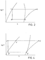
- the specific refrigerating effect provided by the refrigerant is thus h a - h c where ha is the specific enthalpy at point a and h c is the specific enthalpy at point c.
- the volumic refrigerating effect provided by the refrigerant is (h a - h c )/Va where Va is the specific volume of the refrigerant at point a (i.e. the inlet of the compressor 2).
- the specific refrigerating effect is related to the amount of refrigeration provided per unit mass of refrigerant by the refrigeration circuit shown in Figure 1, whereas the volumic refrigeration effect is related to the refrigeration provided per unit power consumed by the compressor 2 and is thus a function of the efficiency with which the refrigeration is provided.
- the method according to the present invention enables the refrigerant to enter the evaporator 8 entirely in the liquid state. This end can be achieved relatively simply without necessitating the provision of extra compression and without the need to reduce the flow rate of refrigerant through the circuit by diverting refrigerant therefrom.
- a sub-ccoler 12 in the form of a heat exchanger is provided intermediate the condenser 4 and the valve 6.
- the heat exchanger 12 has an inlet 16 for liquid nitrogen communicating with a source 14 of liquid nitrogen and an outlet 18 for nitrogen vapour.
- the heat exchanger 12 may for example be of the shell and tube type.
- liquid refrigerant may be of a kind in which cold gas is employed to effect the heat exchange, such cold gas being formed by evaporating liquid nitrogen or other liquid atmospheric gas (for example liquid air).
- Sub-cooled liquid refrigerant thus enters the expansion valve 6.
- the liquid refrigerant is sub-cooled to a temperature such that at the prevailing pressure downstream of the expansion valve 6 not more than 5% by volume of the liquid entering the expansion valve 6 is converted to flash gas, and preferably such that none of the liquid entering the expansion valve 6 is converted to flash gas.
- the liquid entering the expansion valve 6 will typically be at a temperature not substantially below O O C.
- the passage through the expansion valve 6 is utilised to create the necessary evaporating temperature.
- flash gas is formed the proportion of flash gas that is formed increases with increasing temperature drop.
- the proportion of flash gas that is formed can be kept to less than 10% by volume of the refrigerant entering the expansion valve even at low evaporating temperatures.
- the temperature drop across the expansion valve 6 can be eliminated and thus no flash gas formed.
- the volumic refrigerating effect (ha' - hc')/Va' associated with the Figure 3 circuit is similarly greater than the volumic refrigerating effect (ha - hc)/Va associated with the Figure 1 plant.
- the total increase in the specific refrigerating effect is therefore hc'- hx' and the percentage increase in the specific refrigerating effect is (hc' - hx')/(ha' - hx') x 100%.
- Va equals Va'
- the total increase in the volumic refrigerating effect is hc' - hx' and Va'
- increases in the specific and volumic refrigerating effects of at least 10% may be achieved when ammonia is the refrigerant and greater increases can be achieved when a Freon (RTM) is the refrigerant.
- RTM Freon
- the percentage increase gained typically approximates to the percentage increase in the volume of liquid refrigerant leaving the valve when the liquid refrigerant is sub-cooled to the maximum temperature at which the liquid remains enterely in the liquid phase.
- increased heat load may be met without an increase in evaporating temperature since the sub-cooling that is effected in accordance with the invention inherently provides extra refrigeration.
- the condensed refrigerant may, if desired, be sub-cooled to a temperature below the maximum at which the refrigerant remains entirely in the liquid phase. Thus the temperature at which the refrigerant leaves the expansion valve 6 may be lower than that at which it starts to evaporate. This extra sub-cooling makes available additional refrigeration for the chamber 10.
- the liquid refrigerant does not in such an example start to evaporate immediately upon its entry into the evaporator 8. As it flows through the evaporator 8 so the liquid refrigerant is raised in temperature until it beings to evaporate.
- any additional sub-cooling will have the effect of reducing the evaporating pressure in the evaporator 8 and the suction pressure of the compressor 2.
- additional sub-cooling will produce an increase in the specific refrigerating effect over its value at the said point, there will be a decrease in the volumic refrigerating effect in consequence of the fall in the suction pressure of the compressor 2.
- Whether and to what extent such a fall in the volumic refrigerating effect is tolerable will vary according to circumstances, and any such fall may be offset against the increase in the volumic refrigerating effect gained by the sub-cooling of the liquid refrigerant to said point.
- valves such as the expansion valve 6, that is a device which has a passage therethrough and means for opening and closing the passage.
- a simple orifice plate or other such means may be employed.
- the liquid receiver enables a reservoir of liquid refrigerant to be stored in the circuit during periods in which the compressor 2 is not operated.
- the sub-cooler 12 may, instead of being provided intermediate the condenser 4 and the liquid receiver 22, be positioned upstream of the expansion valve 6 and downstream of the receiver 22.
- the plant shown in Figure 5 is provided with a surge drum 24 associated with the evaporator 8.
- the outlet of the expansion valve 6 communicates with a lower inlet to the surge drum 24 and the outlet of the evaporator 8 communicates with another inlet above the lower inlet.
- the surge drum 24 further has an outlet for vapour above said inlets, which outlet communicates with the inlet of the compressor 2.
- the surge drum 24 In operation, typically not all of the liquid refrigerant is evaporated in the evaporator, unevaporated liquid being returned to the surge drum 24. Thus a level of liquid refrigerant is maintained in the surge drum 24.
- the surge drum 24 is provided with upper and lower level sensors 26 with which the expansion valve 6 is operatively associated. The arrangement is such that with normal heat loads in the chamber 10, and without operation of the sub-cooler 12, the liquid level is the surge drum 24 remains below that of the upper sensor 26 so that the expansion valve 6 remains open. In the event of the heat load in the chamber 10 becoming less, there is a tendency for more liquid refrigerant to be returned to the surge drum 24. The level of the liquid in the surge drum 24 therefore rises to that of the upper sensor 26.
- the sensor 26 then generates a signal effective to close the expansion valve 6.
- the surge drum 24 then becomes the only source of liquid refrigerant for the evaporator 8 so that the level of liquid refrigerant in the surge drum 24 falls to that of the lower sensor 26.
- the expansion valve 6 is caused to open and normal operation of the refrigeration circuit resumes.
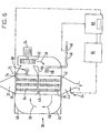
- the heat exchanger shown in Figure 6 is provided with a conduit 46 having a valve 48 disposed therein at a location outside the chamber 30.
- the conduit 46 extends into the chamber 30 and terminates in a liquid nitrogen spray nozzle 50.
- the conduit 46 communicates with a source of liquid nitrogen (not shown in Figure 6).
- a fan 52 is located within the chamber 30 and is able to be driven by means of an external motor 54.
- the chamber is provided with deflectors or baffles 56 which promote circulation of cold gas within the chamber 30 as shown by the arrows 58 when the fan 52 is operated.
- liquid nitrogen is sprayed into the chamber 30 through spray nozzle 50.
- the resulting evaporated nitrogen merges with the circulating gas flow created by operation of the fan 52.
- the cold nitrogen gas that is thus formed passes over the heat exchange tubes 34 and 36 and over the heat exchanger plates 38, 40 and 42 thereby effecting the required sub-cooling of the liquid refrigerant entering the inlet 32 from the condenser 4.
- Cold nitrogen gas leaves the chamber 30 thrr ' jgh an outlet 60. It is then typically vented to the atmosphere at a location where no hazard to people is created. If desired, the cold nitrogen leaving the chamber 30 via the outlet 60 may be used to provide additional cooling for the condenser 4 so as to utilise any residual cold in the vented nitrogen.
- the heat exchanger shown in Figure 6 is provided with temperature control means to enable the spraying of liquid nitrogen through the nozzle 50 to be controlled so as to enable the temperature of the sub-cooled liquid leaving the heat exchanger through the outlet 34 to be kept at or close to a chosen temperature.
- temperature control means to enable the spraying of liquid nitrogen through the nozzle 50 to be controlled so as to enable the temperature of the sub-cooled liquid leaving the heat exchanger through the outlet 34 to be kept at or close to a chosen temperature.
- a first temperature sensor 64 is adapted to transmit a signal representative of the temperature of the liquid in the outlet 44 to a master controller 66 which generates a control signal and transmits it to a slave controller 68 so as to select a set point for the slave controller 68.
- the slave controller 68 also receive an input from a second temperature sensor 70 located in the outlet 60.
- the slave controller 68 generates a control signal for the valve 48. Any changes in the temperature of the liquid condensate entering the inlet 32 of the heat exchanger result in the master controller 66 receiving a signal indicative of this change from the first temperature sensor 64.
- the master controller 66 calls for an appropriate change in the rate of introduction of liquid nitrogen into the chamber 30 so as to provide more or less refrigeration as the case demands to return the sensed temperature to the chosen value.
- the temperature control system may also be provided with means effective to close the valve 48 once the expansion valve 6 shown in Figure 5 is shut for any reason. Similarly, the temperature control system may be provided with means for reopening the valve 48 upon the expansion valve 6 being re-opened.
Landscapes
- Engineering & Computer Science (AREA)
- Physics & Mathematics (AREA)
- Mechanical Engineering (AREA)
- Thermal Sciences (AREA)
- General Engineering & Computer Science (AREA)
- Devices That Are Associated With Refrigeration Equipment (AREA)
- Compressor (AREA)
- Heating, Cooling, Or Curing Plastics Or The Like In General (AREA)
Applications Claiming Priority (2)
| Application Number | Priority Date | Filing Date | Title |
|---|---|---|---|
| GB8517445A GB2177786B (en) | 1985-07-10 | 1985-07-10 | Refrigeration method and apparatus |
| GB8517445 | 1985-07-10 |
Publications (2)
| Publication Number | Publication Date |
|---|---|
| EP0208526A2 true EP0208526A2 (fr) | 1987-01-14 |
| EP0208526A3 EP0208526A3 (fr) | 1989-10-04 |
Family
ID=10582080
Family Applications (1)
| Application Number | Title | Priority Date | Filing Date |
|---|---|---|---|
| EP86305218A Withdrawn EP0208526A3 (fr) | 1985-07-10 | 1986-07-07 | Procédé et appareil frigorifique |
Country Status (5)
| Country | Link |
|---|---|
| EP (1) | EP0208526A3 (fr) |
| JP (1) | JPS6266063A (fr) |
| AU (1) | AU5989086A (fr) |
| GB (1) | GB2177786B (fr) |
| ZA (1) | ZA865039B (fr) |
Cited By (9)
| Publication number | Priority date | Publication date | Assignee | Title |
|---|---|---|---|---|
| NL1000899C2 (en) * | 1994-12-09 | 1996-08-28 | Kempen Koudetechniek B V Van | Cooling system e.g. for refrigerated storage - uses under-cooled refrigerant whose pressure is held constant by regulating pump and valves irrespective of ambient temperature and pressure |
| EP0763848A3 (fr) * | 1995-09-15 | 1998-06-03 | L'air Liquide, Societe Anonyme Pour L'etude Et L'exploitation Des Procedes Georges Claude | Système de réfrigération et méthode de refroidissement d'un suscepteur utilisant ledit système |
| EP0787957A3 (fr) * | 1996-01-30 | 1998-09-09 | The Boc Group, Inc. | Méthode et appareil de refroidissement |
| WO1999013277A1 (fr) * | 1997-09-05 | 1999-03-18 | Fisher & Paykel Limited | Systeme de refrigeration a sous refroidissement variable |
| GB2374666A (en) * | 2001-01-26 | 2002-10-23 | Visteon Global Tech Inc | Measuring and modifying the noise contribution of induction and exhaust systems to engine noise heard by vehicle occupants |
| EP1276215A2 (fr) | 2001-07-12 | 2003-01-15 | General Electric Company | Installation de refroidissement cryogénique pour rotor comportant un enroulement d'excitation supraconducteur à haute température |
| CN102393107A (zh) * | 2011-08-16 | 2012-03-28 | 北京航空航天大学 | 负压液氮过冷器装置及其降低液氮温度的方法 |
| US9605666B2 (en) | 2000-10-17 | 2017-03-28 | Fisher & Paykel Appliances Limited | Linear compressor |
| GB2640543A (en) * | 2024-04-23 | 2025-10-29 | Clean Cold Power Uk Ltd | Improvements in cooling systems |
Families Citing this family (5)
| Publication number | Priority date | Publication date | Assignee | Title |
|---|---|---|---|---|
| DE69205546T2 (de) * | 1991-11-20 | 1996-03-21 | Air Prod & Chem | Kältegerät und Kälteverfahren. |
| JPH11248264A (ja) | 1998-03-04 | 1999-09-14 | Hitachi Ltd | 冷凍装置 |
| GB2371107A (en) * | 2001-01-15 | 2002-07-17 | Air Prod & Chem | Freezing products |
| US20150033771A1 (en) * | 2013-08-02 | 2015-02-05 | Emerald Environmental Technologies | Modular refrigeration and heat reclamation chiller |
| CN113466286B (zh) * | 2021-06-30 | 2023-04-14 | 中国科学院西北生态环境资源研究院 | 模拟混凝土超低温-大温差冻融过程的冻融试验设备 |
Family Cites Families (3)
| Publication number | Priority date | Publication date | Assignee | Title |
|---|---|---|---|---|
| US4286437A (en) * | 1979-07-13 | 1981-09-01 | Tyler Refrigeration Corporation | Energy saving refrigeration system |
| US4285205A (en) * | 1979-12-20 | 1981-08-25 | Martin Leonard I | Refrigerant sub-cooling |
| DE3322474A1 (de) * | 1983-06-22 | 1985-01-17 | Linde Ag, 6200 Wiesbaden | Verfahren zum betreiben eines kaeltemittelkreislaufs und kaeltemittelkreislauf zur durchfuehrung des verfahrens |
-
1985
- 1985-07-10 GB GB8517445A patent/GB2177786B/en not_active Expired
-
1986
- 1986-07-07 EP EP86305218A patent/EP0208526A3/fr not_active Withdrawn
- 1986-07-07 ZA ZA865039A patent/ZA865039B/xx unknown
- 1986-07-09 AU AU59890/86A patent/AU5989086A/en not_active Abandoned
- 1986-07-10 JP JP61162912A patent/JPS6266063A/ja active Pending
Cited By (13)
| Publication number | Priority date | Publication date | Assignee | Title |
|---|---|---|---|---|
| NL1000899C2 (en) * | 1994-12-09 | 1996-08-28 | Kempen Koudetechniek B V Van | Cooling system e.g. for refrigerated storage - uses under-cooled refrigerant whose pressure is held constant by regulating pump and valves irrespective of ambient temperature and pressure |
| EP0763848A3 (fr) * | 1995-09-15 | 1998-06-03 | L'air Liquide, Societe Anonyme Pour L'etude Et L'exploitation Des Procedes Georges Claude | Système de réfrigération et méthode de refroidissement d'un suscepteur utilisant ledit système |
| EP0787957A3 (fr) * | 1996-01-30 | 1998-09-09 | The Boc Group, Inc. | Méthode et appareil de refroidissement |
| WO1999013277A1 (fr) * | 1997-09-05 | 1999-03-18 | Fisher & Paykel Limited | Systeme de refrigeration a sous refroidissement variable |
| US6351950B1 (en) | 1997-09-05 | 2002-03-05 | Fisher & Paykel Limited | Refrigeration system with variable sub-cooling |
| US9605666B2 (en) | 2000-10-17 | 2017-03-28 | Fisher & Paykel Appliances Limited | Linear compressor |
| GB2374666A (en) * | 2001-01-26 | 2002-10-23 | Visteon Global Tech Inc | Measuring and modifying the noise contribution of induction and exhaust systems to engine noise heard by vehicle occupants |
| GB2374666B (en) * | 2001-01-26 | 2003-06-18 | Visteon Global Tech Inc | Method of tuning a vehicle |
| EP1276215A2 (fr) | 2001-07-12 | 2003-01-15 | General Electric Company | Installation de refroidissement cryogénique pour rotor comportant un enroulement d'excitation supraconducteur à haute température |
| EP1276215A3 (fr) * | 2001-07-12 | 2006-06-07 | General Electric Company | Installation de refroidissement cryogénique pour rotor comportant un enroulement d'excitation supraconducteur à haute température |
| CN102393107A (zh) * | 2011-08-16 | 2012-03-28 | 北京航空航天大学 | 负压液氮过冷器装置及其降低液氮温度的方法 |
| CN102393107B (zh) * | 2011-08-16 | 2013-07-03 | 北京航空航天大学 | 负压液氮过冷器装置及其降低液氮温度的方法 |
| GB2640543A (en) * | 2024-04-23 | 2025-10-29 | Clean Cold Power Uk Ltd | Improvements in cooling systems |
Also Published As
| Publication number | Publication date |
|---|---|
| AU5989086A (en) | 1987-01-15 |
| JPS6266063A (ja) | 1987-03-25 |
| GB2177786B (en) | 1989-11-08 |
| GB2177786A (en) | 1987-01-28 |
| EP0208526A3 (fr) | 1989-10-04 |
| ZA865039B (en) | 1987-02-25 |
| GB8517445D0 (en) | 1985-08-14 |
Similar Documents
| Publication | Publication Date | Title |
|---|---|---|
| US3852974A (en) | Refrigeration system with subcooler | |
| US5245836A (en) | Method and device for high side pressure regulation in transcritical vapor compression cycle | |
| JP2865844B2 (ja) | 冷凍システム | |
| US4599873A (en) | Apparatus for maximizing refrigeration capacity | |
| EP3446049B1 (fr) | Système condenseur évaporateur destiné aux systèmes frigorifiques | |
| GB2177786A (en) | Refrigeration method and apparatus | |
| US20020033024A1 (en) | Utilization of harvest and/or melt water from an ice machine for a refrigerant subcool/precool system and method therefor | |
| JPH0771829A (ja) | 蓄熱装置を有する液体冷凍回路の予備冷却装置及び比例制御装置 | |
| CN118328573A (zh) | 一种超低温制冷系统及其控制方法 | |
| JPH0320570A (ja) | 冷却システム及び空気冷却法 | |
| US20100251760A1 (en) | System for refrigeration, heating or air-conditioning technology, particularly refrigeration systems | |
| KR102609998B1 (ko) | 가습기 겸용 유니트 쿨러 | |
| JPH0996476A (ja) | 過冷却水式冷水製造装置 | |
| EP0543194B1 (fr) | Appareil frigorifique et procédé de réfrigération | |
| GB1578966A (en) | Heat exchange arrangements | |
| US4240267A (en) | System for vaporizing carbon dioxide utilizing the heat by-product of the refrigeration system as a heat source | |
| SU1521998A1 (ru) | Каскадна холодильна установка | |
| JPS5829827Y2 (ja) | 冷凍装置の温度制御装置 | |
| KR100249195B1 (ko) | 냉장고 | |
| JPH11316038A (ja) | 空気調和システム | |
| JPH025320Y2 (fr) | ||
| JPH08159584A (ja) | ヘリウム液化冷凍装置及びその運転方法 | |
| WO1996041106A1 (fr) | Refroidissement liquide d'un compresseur | |
| JPS646389B2 (fr) | ||
| JPH053851U (ja) | 冷凍機の凝縮圧力制御装置 |
Legal Events
| Date | Code | Title | Description |
|---|---|---|---|
| PUAI | Public reference made under article 153(3) epc to a published international application that has entered the european phase |
Free format text: ORIGINAL CODE: 0009012 |
|
| AK | Designated contracting states |
Kind code of ref document: A2 Designated state(s): BE DE FR IT NL SE |
|
| PUAL | Search report despatched |
Free format text: ORIGINAL CODE: 0009013 |
|
| AK | Designated contracting states |
Kind code of ref document: A3 Designated state(s): BE DE FR IT NL SE |
|
| 17P | Request for examination filed |
Effective date: 19900330 |
|
| 17Q | First examination report despatched |
Effective date: 19900731 |
|
| STAA | Information on the status of an ep patent application or granted ep patent |
Free format text: STATUS: THE APPLICATION IS DEEMED TO BE WITHDRAWN |
|
| 18D | Application deemed to be withdrawn |
Effective date: 19910212 |
|
| RIN1 | Information on inventor provided before grant (corrected) |
Inventor name: MILLER, JEREMY PAUL |