EP0208553A2 - Appareil de pliage de papier - Google Patents
Appareil de pliage de papier Download PDFInfo
- Publication number
- EP0208553A2 EP0208553A2 EP86305330A EP86305330A EP0208553A2 EP 0208553 A2 EP0208553 A2 EP 0208553A2 EP 86305330 A EP86305330 A EP 86305330A EP 86305330 A EP86305330 A EP 86305330A EP 0208553 A2 EP0208553 A2 EP 0208553A2
- Authority
- EP
- European Patent Office
- Prior art keywords
- web
- fold
- paper
- plates
- paper feed
- Prior art date
- Legal status (The legal status is an assumption and is not a legal conclusion. Google has not performed a legal analysis and makes no representation as to the accuracy of the status listed.)
- Granted
Links
Images

Classifications
-
- B—PERFORMING OPERATIONS; TRANSPORTING
- B65—CONVEYING; PACKING; STORING; HANDLING THIN OR FILAMENTARY MATERIAL
- B65H—HANDLING THIN OR FILAMENTARY MATERIAL, e.g. SHEETS, WEBS, CABLES
- B65H45/00—Folding thin material
- B65H45/12—Folding articles or webs with application of pressure to define or form crease lines
- B65H45/22—Longitudinal folders, i.e. for folding moving sheet material parallel to the direction of movement
- B65H45/221—Longitudinal folders, i.e. for folding moving sheet material parallel to the direction of movement incorporating folding triangles
Definitions
- the present invention relates to apparatus for folding paper, in particular, to apparatus which are used to form longitudinally-extending folds in continuous stationery of the kind frequently associated with computer printers.
- Such apparatus frequently comprises a paper feed arrangement for driving the web through said apparatus, the paper feed arrangement including a support extending transversely of the web and mounting a pair of drive members engageable with opposite longitudinal edges of the web; and paper folding means disposed below, and downstream of, said paper feed arrangement, the paper fclding means including a pair of fold-plates defining a narrow gap through which the web passes to form a fold, the gap defined by the fold plates extending at right angles to the support.
- the paper-folding apparatus of the invention is characterized in that the support carrying the drive members is movable in a transverse direction to alter the position of the web relative to the fold-plates and, hence, to alter the transverse position of the fold formed in the web.
- Such apparatus is capable of forming a stable fold in un-perforated and unscored paper webs. Consequently, it may be used to fold both single and multi-sheet webs. Furthermore, because the folded web exists from the apparatus between a pair of rollers, it can be led away equally easily to either side to produce a right-hand or a left-hand fold as required. When fitted with guide means, the apparatus may also be used to form a fold in a range of transverse positions across the web.
- the web is led by hand through the paper feed arrangement, over the guide means, to the fold plates and the rollers.
- the position of the fold is judged roughly by eye and the folded leading edge of the web inserted between the fold plates and the output rollers.
- the drive elements are then adjusted on their support until they properly engage the edges of the web.
- the web is then advanced through the apparatus. During this movement, the output rollers act on the web so as to align its edges and form a parallel fold.
- the transverse position of the fold can then be adjusted finely bv moving the support together with the drive elements and the web in a transverse direction relative to the paper folding means. Once the correct fold position is achieved, the apparatus will continue to form a straight, parallel, accurately-positioned fold.
- the transverse position of the support, drive elements and web the fold may be formed in any of a range of positions across the web.
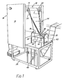
- the paper-folding apparatus shown in the drawings comprises a paper feed arrangement 10, paper-folding means 12 arranged downstream of the paper feed arrangement 10, and guide means 14 disposed between the feed arrangement 10 and the paper folding means 12. All of these are supported on a rigid, generally upright frame 16.
- the frame 16 consists of a pair of substantially vertical side pillars 18 which are mounted at one end of a wheeled trolley 20.
- the frame 16 is provided with wheels to enable the machine to be moved easily from one location in a paper-processing installation to another.
- the trolley 20 is in the form of an open framework defining a cuboid shape with the side pillars 18 extending from opposite longitudinal edges at one of its ends.
- the paper feed arrangement 10 is mounted at the uppermost ends of the side pillars 18 and includes an input roller 22 and a support 24 on which are mounted a pair of drive elements 26 for advancing the paper web 1 through the machine. Between the input roller 22 and support 24, and below them, is mounted a friction bar 23 whose purpose will be described in greater detail below.
- the support 24 extends between the side pillars 18 and can slide in a lengthways direction relative to them.
- the support 24 carries the drive elements 26 which, in use, engage the edges of the web 1 and rotate to drive it in a downstream direction.
- the drive elements 26 may be of any convenient type, for example, pin-type tractor drives.
- the drive elements 26 are mounted on the support 24 so that they can be moved along its length but are provided with means, for example, set-screws or some convenient form of latching device, which allow their position along the support 24 to be fixed.
- the input roller 22 is an idler roller mounted downstream of the support 24 and extending parallel to it.
- a pair of opposite support plates 30 Extending between the support plates 30 in a direction generally perpendicular to the input roller 22, are the various members which make up the paper-folding means 12. These consist primarily of a pair of opposed fold-plates 32 and, mounted directly beneath them a pair of sprung, driven output rollers 34.
- the fold plates 32 are a pair of generally flat metal plates spaced from one another to define a narrow gap.
- the uppermost corners of the plates 32 at their edges remote from the fold are curved outwardly so that they converge their lower edges. In use, the upper edges of the plates 32 act to guide the web into the gap.
- a pair of sprung rollers 34 are mounted immediately below the fold-plates 32.
- the rollers 34 are resiliently-biased into engagement with one another but ? re provided with means (not shown), for example, a lever-operated cam, by which they may be moved apart, if desired.
- the paper folding means 12 is also provided with two pairs of opposite parallel guide rods 36 and 38 extending between the support plates 30.
- the uppermost pair of guide rods 36 is mounted above the fold-plates 32 with the guide rods disposed symmetrically about the gap defined by the fold-plates 32, and a few centimetres apart.
- the lowermost pair of guide rods 38 is mounted at the level where the converging upper portions of the fold-plates 32 come together.
- the guide rods 38 are only a few millimetres apart.
- the guide rods 36 and 38 and the convergent shape of the fold-plates 32 tend to bring together the free edges of the web 1 so that when the web reaches the rollers 34 its edges are only a few millimetres apart and rippling of the web 1 is avoided.
- the V-shaped guide means 14 is formed of tubular metal so as to be rigid and extends at an angle from just beneath the input roller 22 to a vertex just above the fold plates 32.
- the guide means 14 is arranged centrally of both the input roller and the fold-plates 32.
- the arms of the V are secured to a cross-piece 15 which extends between the side pillows 18.
- the distance between the uppermost ends of the arms of the V-shaped guide is at least equal to and, in practice, greater than the width of the web 1.
- the guide means 14 is supported rigidly in position by means of a strut 17 which is fixed at one of its ends to the vertex of the guide member 14 and at its other end to one of the support plates 30.
- the V-shaped guide means 14 is mounted so that it extends in a plane at an angle to the vertical. We have found that for optimum results, the angle the guide means 14 makes with the vertical is equal to half the angle made by the two arms of the guide means where they come together at its lowermost vertex. In order that the fold in the web 1 should be formed as smoothly as possible, the vertex angle of the V-shaped guide means 14 is as acute as space allows and, preferably, around 20°.
- the web 1 is drawn through the apparatus by the combined actions of the drive elements 26 and of the output rollers 34.
- the drive elements 26 and rollers 34 are driven by two separate motors (not shown) which are operated by a single control means.
- the control means which may be a microprocessor, operates the two motors so that the drive elements 26 and rollers 34 are driven simultaneously to advance the web 1.
- the rollers 34 are driven at a slightly higher speed than that of the drive elements 26 but are provided with "magnetic slip" or some other clutch arrangement which permits the required adjustment in their speed. Consequently, when frictionally engaged by the web they tend to adopt the same speed as that imparted to the web 1 by the drive elements 26. Thus, the web 1 is kept under tension but is not subjected to excessive tension which might cause it to burst or tear.
- the control means which operates the drive motors is responsive to the output of a photoelectric sensor 40 mounted on the trolley framework 20.
- the folded web output from the folding apparatus is looped over a further output roller 42 mounted on an upper edge of the trolley framework 20.
- the loop between the output rollers 34 and the further roller 42 will deepen until it is sensed by the photoelectric sensor 40.
- the sensor output signal will cause the drive motors to stop so that the web ceases to advance through the folding apparatus.
- the loop will gradually be taken up until it is no longer detected by the sensor 40.
- the sensor 40 then causes the control means to operate the motors to advance the web through the folding apparatus until the looped web 1 is once again detected by the sensor.
- the web 1 is advanced by the drive elements 26 and the output rollers 34 over the input roller 22 from which it follows an inclined path over the V-shaped guide member 14. Below the guide member 14 the web enters between the fold-plates 32. As the web is advanced between the fold-plates 32, the tension in the web causes it to be pulled around the lower part of the guide member 14 so that its free edges begin to come together. The fold plates 32 form a "soft" fold in the web which then continues between the output rollers 34, which form a "hard” fold.
- the paper web 1 in order to form a proper fold, the paper web 1 must be drawn through the paper-folding means 12 under tension. However, there is a risk that, if the tension is too great, the web 1 will be pulled off the tractor drives 26. To avoid this, the web I passes under the friction bar 23 which is mounted between, but below, the support 24 and the input roller 22. The frictional engagement of the web 1 with the bar 23 prevents the tension in the web 1 being transmitted back to the portion of the web 1 which is engaged by the tractor drives 26. The friction bar 23, thus, provides a form of "strain relief" to prevent the web 1 being pulled off the drive elements 26.
- the folded web 1 exits from between a symmetrical pair of rollers 34, it can be led away equally easily to either side, thus allowing the apparatus to be used to produce either a right-hand or a left-hand fold.
- rollers 34 are, as mentioned above, provided with means which enable them to be moved apart to allow the web to be inserted between them.
- the drive elements 26 are adjusted along the support 24 until they are properly positioned to engage the edges of.the web.
- the motors are then switched on so that the web is advanced a short distance through the apparatus.
- the engagement of the rollers 34 acts to align the longitudinal edges of the web with one another so that the fold produced is parallel to the edges.
- the support 24, together with the already located drive elements 26 is moved transversely so as to adjust the transverse position of the fold relative to the web.
- the apparatus will continue to form a straight fold at the chosen distance from the edpes.
- the location of the fold across the web may be chosen at will, the only constraint limiting the range of possible positions is the ratio of the width of the web to the distance between the side pillars 18, which determines the range of movement of the support 24.
- the paper feed arrangement 10 may also conveniently be provided with means for stripping the perforated edge portions (commonly found on computer stationery) from the web prior to folding.
- the apparatus described may, thus, be used to form a fold in un-perforated, un-scored single or multi-sheet webs at any of a range of transverse positions on the web.
Landscapes
- Folding Of Thin Sheet-Like Materials, Special Discharging Devices, And Others (AREA)
Priority Applications (1)
| Application Number | Priority Date | Filing Date | Title |
|---|---|---|---|
| AT86305330T ATE81099T1 (de) | 1985-07-12 | 1986-07-11 | Apparat zum falten von papier. |
Applications Claiming Priority (2)
| Application Number | Priority Date | Filing Date | Title |
|---|---|---|---|
| GB8517700 | 1985-07-12 | ||
| GB858517700A GB8517700D0 (en) | 1985-07-12 | 1985-07-12 | Paper-folding apparatus |
Publications (3)
| Publication Number | Publication Date |
|---|---|
| EP0208553A2 true EP0208553A2 (fr) | 1987-01-14 |
| EP0208553A3 EP0208553A3 (en) | 1988-04-20 |
| EP0208553B1 EP0208553B1 (fr) | 1992-09-30 |
Family
ID=10582225
Family Applications (1)
| Application Number | Title | Priority Date | Filing Date |
|---|---|---|---|
| EP86305330A Expired EP0208553B1 (fr) | 1985-07-12 | 1986-07-11 | Appareil de pliage de papier |
Country Status (5)
| Country | Link |
|---|---|
| US (1) | US4726578A (fr) |
| EP (1) | EP0208553B1 (fr) |
| AT (1) | ATE81099T1 (fr) |
| DE (1) | DE3686845T2 (fr) |
| GB (1) | GB8517700D0 (fr) |
Cited By (1)
| Publication number | Priority date | Publication date | Assignee | Title |
|---|---|---|---|---|
| AU671075B2 (en) * | 1991-05-13 | 1996-08-15 | General Mills Inc. | Apparatus and methods for flipping and aligning a dough sheet |
Families Citing this family (3)
| Publication number | Priority date | Publication date | Assignee | Title |
|---|---|---|---|---|
| US5104107A (en) * | 1991-05-01 | 1992-04-14 | Wallace Computer Services, Inc. | Fold conditioner and method |
| US5188582A (en) * | 1991-05-31 | 1993-02-23 | Boardman Molded Products, Inc. | Apparatus for forming tear tab lining material |
| DE102004052714A1 (de) * | 2004-10-30 | 2006-05-04 | Man Roland Druckmaschinen Ag | Längfalzvorrichtung |
Family Cites Families (17)
| Publication number | Priority date | Publication date | Assignee | Title |
|---|---|---|---|---|
| US2747865A (en) * | 1951-06-02 | 1956-05-29 | Jr Joseph R Marshall | Booklet forming means and method |
| US3377008A (en) * | 1966-04-27 | 1968-04-09 | American Binder Company Of Cal | Laterally adjustable web feeding means |
| DE1704393B1 (de) * | 1967-04-14 | 1971-11-11 | Windmoeller & Hoelscher | Einrichtung zum falten von werkstoffbahnen um ihre laengs mittellinie zur bildung von halbschlaeuchen |
| US3652357A (en) * | 1968-10-22 | 1972-03-28 | Hayssen Mfg Co | Method and apparatus for web edge alignment |
| JPS5019971B1 (fr) * | 1970-01-14 | 1975-07-11 | ||
| GB1321761A (en) * | 1971-03-26 | 1973-06-27 | Int Computers Ltd | Web feeding apparatus |
| US3786742A (en) * | 1971-10-18 | 1974-01-22 | Polygraph Leipzig | Device for adjusting the spring force on folding rollers |
| US3955737A (en) * | 1974-04-08 | 1976-05-11 | Moore Business Forms, Inc. | Web feed apparatus |
| US3937377A (en) * | 1974-10-11 | 1976-02-10 | American/Durein Company | Chopper for margins of multi-folded paper |
| US3991992A (en) * | 1975-04-24 | 1976-11-16 | Xerox Corporation | Photoelectrophoretic web machine servo drive system |
| US4050361A (en) * | 1976-01-30 | 1977-09-27 | Moore Business Forms, Inc. | Plow folding and heat sealer apparatus for continuous business forms |
| CH628855A5 (fr) * | 1978-04-03 | 1982-03-31 | Fobelmac Sprl | Procede pour acheminer et traiter ou travailler en continu une bande souple pour produire des documents et installation pour sa mise en oeuvre. |
| JPS54154622A (en) * | 1978-05-26 | 1979-12-05 | Toshiba Mach Co Ltd | Paper folding apparatus for rotary press |
| US4189134A (en) * | 1978-06-07 | 1980-02-19 | Saxmayer Corporation | Method for multi-folding a newspaper or the like |
| ATE25063T1 (de) * | 1983-09-28 | 1987-02-15 | Walter Suter | Kreuzfalter fuer endlosformulare. |
| DE3344347A1 (de) * | 1983-12-08 | 1985-06-13 | Süka Hermann Jung GmbH & Co KG, 7512 Rheinstetten | Vorrichtung zum leporelloartigen ablegen von aus schnelldruckern kommendem endlospapier |
| US4516761A (en) * | 1984-04-23 | 1985-05-14 | Bell & Howell Company | Motor driven continuous form folder |
-
1985
- 1985-07-12 GB GB858517700A patent/GB8517700D0/en active Pending
-
1986
- 1986-07-11 EP EP86305330A patent/EP0208553B1/fr not_active Expired
- 1986-07-11 DE DE8686305330T patent/DE3686845T2/de not_active Expired - Fee Related
- 1986-07-11 AT AT86305330T patent/ATE81099T1/de not_active IP Right Cessation
- 1986-07-14 US US06/885,113 patent/US4726578A/en not_active Expired - Lifetime
Cited By (1)
| Publication number | Priority date | Publication date | Assignee | Title |
|---|---|---|---|---|
| AU671075B2 (en) * | 1991-05-13 | 1996-08-15 | General Mills Inc. | Apparatus and methods for flipping and aligning a dough sheet |
Also Published As
| Publication number | Publication date |
|---|---|
| US4726578A (en) | 1988-02-23 |
| ATE81099T1 (de) | 1992-10-15 |
| DE3686845D1 (de) | 1992-11-05 |
| EP0208553A3 (en) | 1988-04-20 |
| GB8517700D0 (en) | 1985-08-21 |
| DE3686845T2 (de) | 1993-03-18 |
| EP0208553B1 (fr) | 1992-09-30 |
Similar Documents
| Publication | Publication Date | Title |
|---|---|---|
| US6279807B1 (en) | Method and apparatus for pinless feeding of web to a utilization device | |
| US5529564A (en) | Apparatus for depositing, guiding and pressing material web parts to be stacked | |
| US5467179A (en) | Turnover device for a web-shaped recording medium | |
| US5279536A (en) | Handling apparatus for a continuous web of Z-fold computer paper | |
| US6321650B1 (en) | Paper web feed unit used in a rotary press and equipped with a paper web traveling tension controller | |
| US6440052B1 (en) | System for directing a leading edge of continuous form paper onto a stack | |
| KR910003002B1 (ko) | 계속적 가요성 웨브(web)의 연속적인 일정한 길이를 간헐적으로 처리하는 방법과 장치 | |
| US9505189B2 (en) | Apparatus for forming a plurality of flexible pouches from a continuous web of film | |
| US5079569A (en) | Laser printer with paper positioning and tensioning features | |
| US5104022A (en) | Continuous paper sheet tearing-up apparatus | |
| US20020084568A1 (en) | Crease plow folder | |
| US5374042A (en) | Paper web separator and deflector | |
| EP0208553B1 (fr) | Appareil de pliage de papier | |
| US5673837A (en) | Apparatus for the high speed stacking of paper sheets | |
| EP0771623B1 (fr) | Dispositif pour la coupe de bandes sans fin | |
| US4732501A (en) | Method and apparatus for loading of a web into a printer | |
| US4504051A (en) | Continuous forms refolder for high speed printers | |
| US4533130A (en) | Apparatus for folding a running web with folding roller and adjustable parallelling bar | |
| JPH07149474A (ja) | 用紙のジグザグ折り用折り畳み装置 | |
| US4926725A (en) | Device for aligning and cutting a web | |
| US4388072A (en) | Depositing device for a pre-folded continuous web of paper in a paper stacker | |
| CA1040226A (fr) | Methode et appareil de pliage de feuilles | |
| EP0382099A2 (fr) | Méthode et appareil pour manipuler des bandes continues dans une imprimante | |
| EP0586201B1 (fr) | Machine d'emballage | |
| JPH0530052Y2 (fr) |
Legal Events
| Date | Code | Title | Description |
|---|---|---|---|
| PUAI | Public reference made under article 153(3) epc to a published international application that has entered the european phase |
Free format text: ORIGINAL CODE: 0009012 |
|
| AK | Designated contracting states |
Kind code of ref document: A2 Designated state(s): AT BE CH DE FR GB IT LI LU NL SE |
|
| PUAL | Search report despatched |
Free format text: ORIGINAL CODE: 0009013 |
|
| AK | Designated contracting states |
Kind code of ref document: A3 Designated state(s): AT BE CH DE FR GB IT LI LU NL SE |
|
| 17P | Request for examination filed |
Effective date: 19880706 |
|
| 17Q | First examination report despatched |
Effective date: 19891024 |
|
| GRAA | (expected) grant |
Free format text: ORIGINAL CODE: 0009210 |
|
| AK | Designated contracting states |
Kind code of ref document: B1 Designated state(s): AT BE CH DE FR GB IT LI LU NL SE |
|
| PG25 | Lapsed in a contracting state [announced via postgrant information from national office to epo] |
Ref country code: AT Effective date: 19920930 Ref country code: BE Effective date: 19920930 Ref country code: NL Effective date: 19920930 Ref country code: SE Effective date: 19920930 |
|
| REF | Corresponds to: |
Ref document number: 81099 Country of ref document: AT Date of ref document: 19921015 Kind code of ref document: T |
|
| REF | Corresponds to: |
Ref document number: 3686845 Country of ref document: DE Date of ref document: 19921105 |
|
| ET | Fr: translation filed | ||
| ITF | It: translation for a ep patent filed | ||
| NLV1 | Nl: lapsed or annulled due to failure to fulfill the requirements of art. 29p and 29m of the patents act | ||
| PLBE | No opposition filed within time limit |
Free format text: ORIGINAL CODE: 0009261 |
|
| STAA | Information on the status of an ep patent application or granted ep patent |
Free format text: STATUS: NO OPPOSITION FILED WITHIN TIME LIMIT |
|
| 26N | No opposition filed | ||
| PGFP | Annual fee paid to national office [announced via postgrant information from national office to epo] |
Ref country code: LU Payment date: 19930928 Year of fee payment: 8 |
|
| EPTA | Lu: last paid annual fee | ||
| PG25 | Lapsed in a contracting state [announced via postgrant information from national office to epo] |
Ref country code: LU Free format text: LAPSE BECAUSE OF NON-PAYMENT OF DUE FEES Effective date: 19940711 |
|
| PGFP | Annual fee paid to national office [announced via postgrant information from national office to epo] |
Ref country code: FR Payment date: 19970109 Year of fee payment: 11 |
|
| PGFP | Annual fee paid to national office [announced via postgrant information from national office to epo] |
Ref country code: CH Payment date: 19970120 Year of fee payment: 11 |
|
| PG25 | Lapsed in a contracting state [announced via postgrant information from national office to epo] |
Ref country code: LI Free format text: LAPSE BECAUSE OF NON-PAYMENT OF DUE FEES Effective date: 19970731 Ref country code: CH Free format text: LAPSE BECAUSE OF NON-PAYMENT OF DUE FEES Effective date: 19970731 |
|
| REG | Reference to a national code |
Ref country code: CH Ref legal event code: PL |
|
| PG25 | Lapsed in a contracting state [announced via postgrant information from national office to epo] |
Ref country code: FR Free format text: LAPSE BECAUSE OF NON-PAYMENT OF DUE FEES Effective date: 19980331 |
|
| REG | Reference to a national code |
Ref country code: FR Ref legal event code: ST |
|
| REG | Reference to a national code |
Ref country code: GB Ref legal event code: IF02 |
|
| PGFP | Annual fee paid to national office [announced via postgrant information from national office to epo] |
Ref country code: GB Payment date: 20020703 Year of fee payment: 17 |
|
| PGFP | Annual fee paid to national office [announced via postgrant information from national office to epo] |
Ref country code: DE Payment date: 20020730 Year of fee payment: 17 |
|
| PG25 | Lapsed in a contracting state [announced via postgrant information from national office to epo] |
Ref country code: GB Free format text: LAPSE BECAUSE OF NON-PAYMENT OF DUE FEES Effective date: 20030711 |
|
| PG25 | Lapsed in a contracting state [announced via postgrant information from national office to epo] |
Ref country code: DE Free format text: LAPSE BECAUSE OF NON-PAYMENT OF DUE FEES Effective date: 20040203 |
|
| GBPC | Gb: european patent ceased through non-payment of renewal fee |
Effective date: 20030711 |
|
| PG25 | Lapsed in a contracting state [announced via postgrant information from national office to epo] |
Ref country code: IT Free format text: LAPSE BECAUSE OF NON-PAYMENT OF DUE FEES;WARNING: LAPSES OF ITALIAN PATENTS WITH EFFECTIVE DATE BEFORE 2007 MAY HAVE OCCURRED AT ANY TIME BEFORE 2007. THE CORRECT EFFECTIVE DATE MAY BE DIFFERENT FROM THE ONE RECORDED. Effective date: 20050711 |
|
| PG25 | Lapsed in a contracting state [announced via postgrant information from national office to epo] |
Ref country code: FR Free format text: LAPSE BECAUSE OF NON-PAYMENT OF DUE FEES Effective date: 19960731 |