EP0208872A1 - Procédé pour la transmission de données numériques - Google Patents
Procédé pour la transmission de données numériques Download PDFInfo
- Publication number
- EP0208872A1 EP0208872A1 EP86106762A EP86106762A EP0208872A1 EP 0208872 A1 EP0208872 A1 EP 0208872A1 EP 86106762 A EP86106762 A EP 86106762A EP 86106762 A EP86106762 A EP 86106762A EP 0208872 A1 EP0208872 A1 EP 0208872A1
- Authority
- EP
- European Patent Office
- Prior art keywords
- phase
- transmission
- transmission section
- sections
- symbols
- Prior art date
- Legal status (The legal status is an assumption and is not a legal conclusion. Google has not performed a legal analysis and makes no representation as to the accuracy of the status listed.)
- Granted
Links
- 230000005540 biological transmission Effects 0.000 title claims abstract description 76
- 238000000034 method Methods 0.000 title claims abstract description 31
- 230000015572 biosynthetic process Effects 0.000 claims description 2
- 238000011156 evaluation Methods 0.000 claims description 2
- 230000001360 synchronised effect Effects 0.000 abstract 1
- 230000010363 phase shift Effects 0.000 description 4
- 238000010586 diagram Methods 0.000 description 3
- 230000001427 coherent effect Effects 0.000 description 2
- 230000002349 favourable effect Effects 0.000 description 2
- 238000012935 Averaging Methods 0.000 description 1
- 235000008694 Humulus lupulus Nutrition 0.000 description 1
- 238000004891 communication Methods 0.000 description 1
- 238000001514 detection method Methods 0.000 description 1
- 230000010354 integration Effects 0.000 description 1
- 230000000717 retained effect Effects 0.000 description 1
Images

Classifications
-
- H—ELECTRICITY
- H04—ELECTRIC COMMUNICATION TECHNIQUE
- H04L—TRANSMISSION OF DIGITAL INFORMATION, e.g. TELEGRAPHIC COMMUNICATION
- H04L27/00—Modulated-carrier systems
- H04L27/18—Phase-modulated carrier systems, i.e. using phase-shift keying
-
- H—ELECTRICITY
- H04—ELECTRIC COMMUNICATION TECHNIQUE
- H04B—TRANSMISSION
- H04B1/00—Details of transmission systems, not covered by a single one of groups H04B3/00 - H04B13/00; Details of transmission systems not characterised by the medium used for transmission
- H04B1/69—Spread spectrum techniques
- H04B1/713—Spread spectrum techniques using frequency hopping
-
- H—ELECTRICITY
- H04—ELECTRIC COMMUNICATION TECHNIQUE
- H04B—TRANSMISSION
- H04B1/00—Details of transmission systems, not covered by a single one of groups H04B3/00 - H04B13/00; Details of transmission systems not characterised by the medium used for transmission
- H04B1/69—Spread spectrum techniques
- H04B1/713—Spread spectrum techniques using frequency hopping
- H04B1/7156—Arrangements for sequence synchronisation
Definitions
- the invention relates to a method for transmitting digital data according to the preamble of claim 1.
- phase shift keying (abbreviated PSK) is used as the modulation method in the article mentioned.
- FSK frequency shift keying
- the phase of the carrier wave must therefore usually be redetermined in each transmission section between two frequency hops.
- this phase determination is called a difficult problem.
- this problem could be solved by transmitting special synchronization information, for example in a preamble, in addition to the data in each transmission section.
- special synchronization information for example in a preamble
- the invention as characterized in the claims, achieves the object of specifying method steps for a method of the type mentioned at the outset, by means of which a simple, in particular energetically favorable and nevertheless reliable determination of the relative phase relationship of the different transmission sections is made possible.
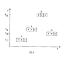
- FIG. 1 shows in a frequency-time diagram, the axes of which are denoted by f and t, in a schematic manner how, according to the invention, six symbols 1 to 6 can be transmitted, for example, in four transmission sections I to IV.
- the symbols 1 to 6 are said to have been formed by modulating the phase of a carrier wave by one of the phase angles from the set [0, Z ⁇ / n, ..., (n-1) 2 ⁇ / n] with n elements in a transmitter.
- the four transmission sections are drawn offset from one another in the vertical direction in FIG. 1 in order to clarify that the carrier wave in the individual transmission sections I to IV should have different frequencies, for example the frequencies designated f r to f IV .
- FIG. 1 Three symbols are transmitted in FIG. 1 for each transmission section.
- all of the symbols 1 to 6 are transmitted twice, and in such a way that there are never two identical symbols in the same transmission section and, moreover, not two symbols from one transmission section in a single other transmission section.
- the multiple transmission of all symbols is not necessary per se for the success of the method according to the invention. It would in principle be sufficient to additionally transmit only one symbol from each transmission section in another transmission section.
- the double transmission of all symbols provides redundant information for the synchronization of the individual transmission sections, which is particularly advantageous with regard to transmission errors due to interference in the transmission channel.
- phase ie the basic phase of the modulated carrier wave. Since the phase coherence in the phase jumps between the individual transmission sections I to IV can be lost, it is necessary to redetermine the phase position of the carrier wave in the receiver for each transmission section I to IV.
- the phases of the carrier wave within of the individual transmission sections I to IV are also referred to below as block phases.
- the determination of the block phases is initially carried out using an estimation method, such as that described below, except for an n-fold phase uncertainty, which in itself is derived from an article by Andrew J. Viterbi and Audrey U. Viterbi with the title "Nonlinear Estimation of PSK- Modulated Carrier Phase with Application to Burst Digital Transmission ", IEEE Transactions On Information Theory, Vol. IT-29, No. 4, July 1983, pages 543-551, in particular from FIG. 2 with the associated description, and therefore need not be described in detail here.
- the carrier wave received in the receiver, modulated with the symbols 1 to 6 is first of all with a sine signal generated in the receiver, for example by a sine generator, with essentially the same frequency - the sine generator has to continuously adapt its frequency to the frequency jumps of the carrier wave - but as desired Phase position and multiplied by a cosine signal corresponding to this.
- the frequency components are filtered out of the resulting product signals, for example by integration, so that largely constant components remain for the transmission duration of the individual symbols 1 to 6.
- These can be understood as the imaginary and real components of first pointers in the complex Gaussian plane jy-x, as shown in Fig. 2a).
- the pointer Z with its components x 1 and y, the symbol 1, the pointer Z 2 with the components x 2 and y 2, the symbol 2 and the pointer Z 3 with the components x 3 and y 3 correspond to the symbol 3 of the transmission section I of FIG. 1.
- the phases are also shown in FIG. 2 a) and denoted by ⁇ 1 to ⁇ 3 angles, which include the above-mentioned pointers Z 1 to Z 3 with the positive real axis x, which corresponds to the phase position of the sine signal generated in the receiver.
- These phase angles ⁇ 1 to ⁇ 3 are part of the n possible values of the sought block phase of the transmission section I.
- n 4
- the pointers Z 1 to Z 3 in FIG. 2 a) would all have the same length and exactly angles ⁇ / 2 or ⁇ relative to one another. Due to the noise and interference in the transmission channel, however, in practice both the lengths of the pointers and their relative phase angles deviate from the values ⁇ / 2 and ⁇ mentioned, which is also shown in FIG. 2a). In order to minimize the influence of noise and interference when determining the block phase, it is advisable to determine the block phase by averaging over several, preferably even all, of the symbols transmitted within the respective transmission section, here via symbols 1 to 3.
- the resultant from the hands Z 1 to Z 3 hands Z '1 Z' 3 2) are again shown in b of the Gaussian plane in Fig...
- all the pointers Z ' 1 to Z' 3 coincide in such a way that their real and imaginary components x ' 1 to x' 3 or y ' 1 to y' 3 can be averaged in each case.
- the desired mean phase I / n (arctg (y / x) can then be determined relative to the phase position of the sinusoidal signal, except for the phase uncertainty still mentioned.
- this phase uncertainty means that the true block phase of the transmission section, instead of, as can be seen from FIG. 2 b), 0.18 ⁇ could also be 0.68 ⁇ , 1.18 ⁇ or 1.68 ⁇ .
- the final block phases of the transmission sections I to IV can be obtained by evaluating the synchronization information obtained by the multiple transmission of the symbols 1 to 6.
- the n possible states of the individual symbols must be determined within the individual transmission sections using the still unsafe block phases, the individual states being values of complex numbers from the set [exp (j0), exp (j2 ⁇ / n), ... , exp (j (n-1) 2 ⁇ / n)].
- the state value of the symbol from the transmission section with index i is multiplied by the conjugate complex state value of the symbol from the transmission section with index k and the products d ik equated with products a i a * k , where a. an initially unknown complex phase error value assigned to the transmission section with the index i and a * k the conjugate complex value of a likewise still unknown complex, means the phase error value a k assigned to the transmission section with the index k.
- the unknown phase error values can be determined from at least one number of equations of the system of equations equal to the number of the predetermined transmission sections.
- a total of six equations are available for the four unknown phase error values a I to a IV , ie the system of equations chosen as an example is over-determined.
- This determination results from the fact that in the example of FIG. 1 each symbol was transmitted twice. As already mentioned, it is in itself sufficient to additionally transmit only one symbol from each transmission section in another transmission section. This would result in a simply determined system of equations.
- an overdetermined system of equations like the one above, provides a certain redundancy for the determination of the unknown phase error values, which can be of great advantage especially with regard to transmission errors.
- phase error values in the example the phase error values a I to a IV , are used to correct the block phases after they have been determined, specifically the block phases determined provisionally within the individual transmission sections by a phase angle corresponding to the negative argument of the phase error value assigned to the respective transmission section corrected.
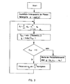
- phase error values can be determined particularly elegantly in the following manner, which is also shown in the flowchart in FIG. 3: All phase error values are assigned exp (j0) as the initial value. Then a number m of sums corresponding to the predetermined number of transmission sections becomes formed, the d ik , a i , a k again have the meaning already defined above and the star should again indicate the conjugate complex. From the sums formed, the one with the smallest real part and its index i are determined.
- phase error values are interpreted as their final values to be determined; otherwise the argument of the phase error value a i is corrected by -2 T r / n and the sum formation, the index determination and the sign determination are carried out again, ie a loop is run through.
- the easiest way to do this is to use a digital computer.
Landscapes
- Engineering & Computer Science (AREA)
- Computer Networks & Wireless Communication (AREA)
- Signal Processing (AREA)
- Digital Transmission Methods That Use Modulated Carrier Waves (AREA)
- Communication Control (AREA)
Applications Claiming Priority (2)
| Application Number | Priority Date | Filing Date | Title |
|---|---|---|---|
| CH3068/85 | 1985-07-15 | ||
| CH3068/85A CH668873A5 (de) | 1985-07-15 | 1985-07-15 | Verfahren zur uebertragung digitaler daten. |
Publications (2)
| Publication Number | Publication Date |
|---|---|
| EP0208872A1 true EP0208872A1 (fr) | 1987-01-21 |
| EP0208872B1 EP0208872B1 (fr) | 1990-09-05 |
Family
ID=4247911
Family Applications (1)
| Application Number | Title | Priority Date | Filing Date |
|---|---|---|---|
| EP86106762A Expired - Lifetime EP0208872B1 (fr) | 1985-07-15 | 1986-05-17 | Procédé pour la transmission de données numériques |
Country Status (5)
| Country | Link |
|---|---|
| US (1) | US4756009A (fr) |
| EP (1) | EP0208872B1 (fr) |
| CH (1) | CH668873A5 (fr) |
| DE (1) | DE3673903D1 (fr) |
| NO (1) | NO170610C (fr) |
Cited By (3)
| Publication number | Priority date | Publication date | Assignee | Title |
|---|---|---|---|---|
| EP0238813A3 (en) * | 1986-02-27 | 1989-05-10 | Bbc Brown Boveri Ag | Method for transmitting data over mains lines |
| US5093828A (en) * | 1989-03-21 | 1992-03-03 | Datawatt B.V. | Method of exchanging data |
| GB2278257A (en) * | 1993-05-05 | 1994-11-23 | British Broadcasting Corp | Receiving equipment for digital transmissions |
Families Citing this family (5)
| Publication number | Priority date | Publication date | Assignee | Title |
|---|---|---|---|---|
| US5088113A (en) * | 1990-01-02 | 1992-02-11 | At&T Bell Laboratories | Diversity coded modulation |
| US5638412A (en) * | 1994-06-15 | 1997-06-10 | Qualcomm Incorporated | Method for providing service and rate negotiation in a mobile communication system |
| US5694108A (en) * | 1996-05-01 | 1997-12-02 | Abb Power T&D Company Inc. | Apparatus and methods for power network coupling |
| US5978371A (en) * | 1997-03-31 | 1999-11-02 | Abb Power T&D Company Inc. | Communications module base repeater |
| US5933073A (en) * | 1997-07-07 | 1999-08-03 | Abb Power T&D Company Inc. | Apparatus and methods for power network coupling |
Citations (4)
| Publication number | Priority date | Publication date | Assignee | Title |
|---|---|---|---|---|
| US3736507A (en) * | 1971-08-19 | 1973-05-29 | Communications Satellite Co | Phase ambiguity resolution for four phase psk communications systems |
| US3962637A (en) * | 1974-11-11 | 1976-06-08 | Hycom Incorporated | Ultrafast adaptive digital modem |
| US4066964A (en) * | 1967-01-06 | 1978-01-03 | Rockwell International Corporation | Communication system |
| DE3230726A1 (de) * | 1982-08-18 | 1984-02-23 | Siemens AG, 1000 Berlin und 8000 München | Verfahren zur stoerresistenten funkuebertragung auf kurzwelle |
Family Cites Families (3)
| Publication number | Priority date | Publication date | Assignee | Title |
|---|---|---|---|---|
| US3310741A (en) * | 1965-07-21 | 1967-03-21 | Nederlanden Staat | System for alternately transmitting coded messages on a predetermined plurality of carrier frequencies from a plurality of transistors |
| US4349915A (en) * | 1981-02-02 | 1982-09-14 | General Electric Company | Minimization of multipath and doppler effects in radiant energy communication systems |
| US4583231A (en) * | 1983-11-02 | 1986-04-15 | General Electric Company | Method of, and apparatus for, frequency-hopped frequency-shift-keyed digital data communications |
-
1985
- 1985-07-15 CH CH3068/85A patent/CH668873A5/de not_active IP Right Cessation
-
1986
- 1986-05-17 DE DE8686106762T patent/DE3673903D1/de not_active Expired - Lifetime
- 1986-05-17 EP EP86106762A patent/EP0208872B1/fr not_active Expired - Lifetime
- 1986-06-03 NO NO862203A patent/NO170610C/no unknown
- 1986-07-02 US US06/881,235 patent/US4756009A/en not_active Expired - Fee Related
Patent Citations (4)
| Publication number | Priority date | Publication date | Assignee | Title |
|---|---|---|---|---|
| US4066964A (en) * | 1967-01-06 | 1978-01-03 | Rockwell International Corporation | Communication system |
| US3736507A (en) * | 1971-08-19 | 1973-05-29 | Communications Satellite Co | Phase ambiguity resolution for four phase psk communications systems |
| US3962637A (en) * | 1974-11-11 | 1976-06-08 | Hycom Incorporated | Ultrafast adaptive digital modem |
| DE3230726A1 (de) * | 1982-08-18 | 1984-02-23 | Siemens AG, 1000 Berlin und 8000 München | Verfahren zur stoerresistenten funkuebertragung auf kurzwelle |
Non-Patent Citations (2)
| Title |
|---|
| ARCHIV FÜR ELEKTRONIK UND ÜBERTRAGUNGSTECHNIK, Band 33, Nr. 7/8, Juli/August 1979, Seiten 269-277, Stuttgart, DE; J. KREBSER: "Übertragungsverhalten von FH-DPSK-Systemen bei frequenzselektivem Signalschwund und Teilbandstörungen" * |
| IEEE TRANSACTIONS ON INFORMATION THEORY, Band IT-29, Nr. 4, Juli 1983, Seiten 543-551, IEEE, New York, US; A.J. VITERBI et al.: "Nonlinear estimation of PSK-modulated carrier phase with application to burst digital transmission" * |
Cited By (5)
| Publication number | Priority date | Publication date | Assignee | Title |
|---|---|---|---|---|
| EP0238813A3 (en) * | 1986-02-27 | 1989-05-10 | Bbc Brown Boveri Ag | Method for transmitting data over mains lines |
| US5093828A (en) * | 1989-03-21 | 1992-03-03 | Datawatt B.V. | Method of exchanging data |
| GB2278257A (en) * | 1993-05-05 | 1994-11-23 | British Broadcasting Corp | Receiving equipment for digital transmissions |
| GB2278257B (en) * | 1993-05-05 | 1996-10-02 | British Broadcasting Corp | Receiving equipment for digital transmissions |
| US5838734A (en) * | 1993-05-05 | 1998-11-17 | British Broadcasting Corporation | Compensation for local oscillator errors in an OFDM receiver |
Also Published As
| Publication number | Publication date |
|---|---|
| DE3673903D1 (de) | 1990-10-11 |
| NO170610C (no) | 1992-11-04 |
| NO170610B (no) | 1992-07-27 |
| NO862203L (no) | 1987-01-16 |
| EP0208872B1 (fr) | 1990-09-05 |
| US4756009A (en) | 1988-07-05 |
| NO862203D0 (no) | 1986-06-03 |
| CH668873A5 (de) | 1989-01-31 |
Similar Documents
| Publication | Publication Date | Title |
|---|---|---|
| DE2448638C2 (fr) | ||
| DE3604849C2 (de) | Vorrichtung und Verfahren zur Auslöschung von Kreuzpolarisationsstörungen | |
| DE3022553C2 (de) | Echoannullierer für ein synchrones Duplex-Datenübertragunssystem | |
| EP0169520A2 (fr) | Récepteur pour signaux à spectre étalé | |
| DE2648273A1 (de) | Verfahren und vorrichtung zur verringerung des verstaendlichen nebensprechens in einseitenband-funkuebertragungssystemen | |
| EP0019755B1 (fr) | Procédé et circuit pour la suppression d'un signal de diaphonic pendant la transmission de données sur deux fils | |
| DE3243464A1 (de) | Verfahren zur kohaerenten erfassung und demodulation einer sich in irgendeinem polarisationszustand befindenden, phasenmodulierten traegerwelle und vorrichtung zur durchfuehrung des verfahrens | |
| DE3751101T2 (de) | Modulator zur Erzeugung von PSK-Signalen mit konstanter Amplitude. | |
| DE2918269A1 (de) | Diversity-system | |
| DE2321111B2 (de) | Automatisch adaptierender Transversalentzerrer | |
| EP0208872B1 (fr) | Procédé pour la transmission de données numériques | |
| DE3601576A1 (de) | Empfaenger fuer bandgespreizte signale | |
| DE1934296C3 (de) | Vorrichtung zur Übertragung rechteckiger synchroner Informationsimpulse | |
| DE2801142C2 (de) | Verfahren zur Navigation und Standortbestimmung eines Fahrzeuges | |
| WO2009090138A1 (fr) | Procédé pour différencier deux signaux | |
| DE2808544C2 (de) | Kombinierte Radar- und Nachrichtenübertragungseinrichtung | |
| DE2029836A1 (fr) | ||
| DE2712474B2 (de) | Demodulationssystem für eine mehrphasig und mehrstufig überlagerungsmodulierte Trägerwelle | |
| DE2221084C3 (de) | Kohärentes Datenübertragungsverfahren | |
| DE3429959C2 (de) | Verfahren zur Nachrichtenübertragung mittels Frequenzumtast-Modulation | |
| DE2725099A1 (de) | Bodenstation fuer ein navigationssystem mit einer antenne fuer elektronische strahlschwenkung | |
| DE69209890T2 (de) | MSK-Modulator | |
| DE2721283C2 (de) | Drahtloses digitales Informationsübertragungssystem für sehr kurze Wellen | |
| DE3010537A1 (de) | Anordnung zur uebertragung digitaler daten | |
| EP1018221B1 (fr) | Procede et circuit pour la transmission de messages en utilisant des approximations de fonctions hermitiennes |
Legal Events
| Date | Code | Title | Description |
|---|---|---|---|
| PUAI | Public reference made under article 153(3) epc to a published international application that has entered the european phase |
Free format text: ORIGINAL CODE: 0009012 |
|
| AK | Designated contracting states |
Kind code of ref document: A1 Designated state(s): CH DE GB IT LI |
|
| 17P | Request for examination filed |
Effective date: 19870606 |
|
| RAP1 | Party data changed (applicant data changed or rights of an application transferred) |
Owner name: BBC BROWN BOVERI AG |
|
| 17Q | First examination report despatched |
Effective date: 19890309 |
|
| GRAA | (expected) grant |
Free format text: ORIGINAL CODE: 0009210 |
|
| AK | Designated contracting states |
Kind code of ref document: B1 Designated state(s): CH DE GB IT LI |
|
| ITF | It: translation for a ep patent filed | ||
| REF | Corresponds to: |
Ref document number: 3673903 Country of ref document: DE Date of ref document: 19901011 |
|
| GBT | Gb: translation of ep patent filed (gb section 77(6)(a)/1977) | ||
| PLBE | No opposition filed within time limit |
Free format text: ORIGINAL CODE: 0009261 |
|
| STAA | Information on the status of an ep patent application or granted ep patent |
Free format text: STATUS: NO OPPOSITION FILED WITHIN TIME LIMIT |
|
| 26N | No opposition filed | ||
| ITPR | It: changes in ownership of a european patent |
Owner name: CESSIONE;DATAWATT B.V. |
|
| REG | Reference to a national code |
Ref country code: CH Ref legal event code: PUE Owner name: DATAWATT B.V. |
|
| ITF | It: translation for a ep patent filed | ||
| REG | Reference to a national code |
Ref country code: GB Ref legal event code: 732 |
|
| PGFP | Annual fee paid to national office [announced via postgrant information from national office to epo] |
Ref country code: CH Payment date: 19930330 Year of fee payment: 8 |
|
| ITTA | It: last paid annual fee | ||
| PG25 | Lapsed in a contracting state [announced via postgrant information from national office to epo] |
Ref country code: LI Effective date: 19940531 Ref country code: CH Effective date: 19940531 |
|
| REG | Reference to a national code |
Ref country code: CH Ref legal event code: PL |
|
| PGFP | Annual fee paid to national office [announced via postgrant information from national office to epo] |
Ref country code: GB Payment date: 19950413 Year of fee payment: 10 |
|
| PGFP | Annual fee paid to national office [announced via postgrant information from national office to epo] |
Ref country code: DE Payment date: 19950421 Year of fee payment: 10 |
|
| PG25 | Lapsed in a contracting state [announced via postgrant information from national office to epo] |
Ref country code: GB Effective date: 19960517 |
|
| GBPC | Gb: european patent ceased through non-payment of renewal fee |
Effective date: 19960517 |
|
| PG25 | Lapsed in a contracting state [announced via postgrant information from national office to epo] |
Ref country code: DE Effective date: 19970201 |
|
| PG25 | Lapsed in a contracting state [announced via postgrant information from national office to epo] |
Ref country code: IT Free format text: LAPSE BECAUSE OF NON-PAYMENT OF DUE FEES;WARNING: LAPSES OF ITALIAN PATENTS WITH EFFECTIVE DATE BEFORE 2007 MAY HAVE OCCURRED AT ANY TIME BEFORE 2007. THE CORRECT EFFECTIVE DATE MAY BE DIFFERENT FROM THE ONE RECORDED. Effective date: 20050517 |