EP0209191A1 - Tube d'affichage - Google Patents
Tube d'affichage Download PDFInfo
- Publication number
- EP0209191A1 EP0209191A1 EP86201199A EP86201199A EP0209191A1 EP 0209191 A1 EP0209191 A1 EP 0209191A1 EP 86201199 A EP86201199 A EP 86201199A EP 86201199 A EP86201199 A EP 86201199A EP 0209191 A1 EP0209191 A1 EP 0209191A1
- Authority
- EP
- European Patent Office
- Prior art keywords
- window
- display
- space
- cooling
- display tube
- Prior art date
- Legal status (The legal status is an assumption and is not a legal conclusion. Google has not performed a legal analysis and makes no representation as to the accuracy of the status listed.)
- Granted
Links
- 238000001816 cooling Methods 0.000 claims abstract description 23
- 239000000110 cooling liquid Substances 0.000 claims abstract description 16
- 239000007788 liquid Substances 0.000 claims description 5
- 239000012809 cooling fluid Substances 0.000 claims description 2
- LYCAIKOWRPUZTN-UHFFFAOYSA-N Ethylene glycol Chemical compound OCCO LYCAIKOWRPUZTN-UHFFFAOYSA-N 0.000 description 2
- 238000010276 construction Methods 0.000 description 2
- 230000008878 coupling Effects 0.000 description 2
- 238000010168 coupling process Methods 0.000 description 2
- 238000005859 coupling reaction Methods 0.000 description 2
- -1 for example Substances 0.000 description 2
- 229910052751 metal Inorganic materials 0.000 description 2
- 239000002184 metal Substances 0.000 description 2
- 230000003287 optical effect Effects 0.000 description 2
- 229920003002 synthetic resin Polymers 0.000 description 2
- 239000000057 synthetic resin Substances 0.000 description 2
- 239000004411 aluminium Substances 0.000 description 1
- 229910052782 aluminium Inorganic materials 0.000 description 1
- XAGFODPZIPBFFR-UHFFFAOYSA-N aluminium Chemical compound [Al] XAGFODPZIPBFFR-UHFFFAOYSA-N 0.000 description 1
- 238000010894 electron beam technology Methods 0.000 description 1
- 239000011521 glass Substances 0.000 description 1
- WGCNASOHLSPBMP-UHFFFAOYSA-N hydroxyacetaldehyde Natural products OCC=O WGCNASOHLSPBMP-UHFFFAOYSA-N 0.000 description 1
- 238000007689 inspection Methods 0.000 description 1
- 239000000463 material Substances 0.000 description 1
- 229920003229 poly(methyl methacrylate) Polymers 0.000 description 1
- 239000004926 polymethyl methacrylate Substances 0.000 description 1
- XLYOFNOQVPJJNP-UHFFFAOYSA-N water Substances O XLYOFNOQVPJJNP-UHFFFAOYSA-N 0.000 description 1
Images
Classifications
-
- H—ELECTRICITY
- H01—ELECTRIC ELEMENTS
- H01J—ELECTRIC DISCHARGE TUBES OR DISCHARGE LAMPS
- H01J7/00—Details not provided for in the preceding groups and common to two or more basic types of discharge tubes or lamps
- H01J7/24—Cooling arrangements; Heating arrangements; Means for circulating gas or vapour within the discharge space
- H01J7/26—Cooling arrangements; Heating arrangements; Means for circulating gas or vapour within the discharge space by flow of fluid through passages associated with tube or lamp
-
- H—ELECTRICITY
- H01—ELECTRIC ELEMENTS
- H01J—ELECTRIC DISCHARGE TUBES OR DISCHARGE LAMPS
- H01J29/00—Details of cathode-ray tubes or of electron-beam tubes of the types covered by group H01J31/00
- H01J29/006—Arrangements for eliminating unwanted temperature effects
Definitions
- the invention relates to a display tube comprising an evacuated envelope having a display window which on its inside comprises a display screen and in front of which on its outside a transparent second window is provided substantially parallel to the outside and with a space between the display window and the second window which is destined for laminar flow of a transparent cooling liquid.
- Such a display tube is disclosed in Netherlands Patent Application 8300114 laid open to plublic inspection.
- Cooling of display tubes is of particular importance in display tubes for projection television, in which for obtaining the required great brightnesses the display screens are scanned by electron beams with high beam currents.
- Ths use of a laminar flow of cooling liquid prevents inhomogeneities occurring in the cooling liquid and hence differences in refractive indices which are expressed as refractive patterns in the displayed picture.
- the spacing between the display window and the second window generally is approximately 3 to 4 mm.
- One of the objects of the invention is to achieve the said improvements at least to a considerable extent.
- the display tube mentioned in the opening paragraph is characterized according to the invention in that a third window is provided substantially parallel to and in front of the side of the second window remote from the display window, said third window forming with the second window a second space containing the cooling liquid, the second space communicating with the first mentioned space beyond the light path of the display tube, and in that a closed cooling system is provided beyond said light path, the cooling system communicating with said first mentioned and said second spaces whereby the transparent cooling fluid in said second space flows in counter current to the liquid in the first mentioned space.
- the cooling system and the second window can particularly simply be assembled and disassembled due to the absence of hoses, pumps and associated arrangements, while the closed cooling system proves to provide a cooling which is sufficiently large to use the display tube at substantially any suitable angle.
- the light path no glass components need be used in the light path but, for example, a synthetic resin may be used for the second and the third window and metal components may be used in the cooling system.
- the third window is a part of a system of lenses.
- This construction promotes a rapid and accurate positioning of the display tube with respect to the system of lenses. Optimum results are obtained with optical coupling of the windows and the cooling liquid.
- the refractive indices of the cooling liuquid and of the display window and the second and third windows are adapted to each other.
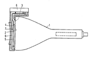
- FIG. 1 is a diagrammatic sectional view of a display tube according to the invention.
- the display tube comprises an evacuated envelope 1 having a substantially rectangular display window 2 which comprises a display screen 3 on its inside and in front of which on its outside a transparent second window 4 is provided so as to be substantially parallel with the outside and having a space 5 between the display window 2 and the second window 4 which space is destined to laminar flow of a transparent liquid.
- a third window 7 is provided substantially parallel to the remote side and with the second window 4forms a second space 8 to return, in counter current with respect to the heatedliquid, the cooled cooling liquid to the first space 5 between the display window 2 and the second window 4.
- the first and second spaces 5, 8 communicate with each other beyond the light path of the display tube.
- the flow of the cooling liquid is indicated by the arrows. If the cooling system 6 does not comprise a pump then the liquid flow is by convection.
- the third window 7 preferably is a part of a system of lenses.
- the spacing between the display window 2 and the second window 4 is 3 to 4 mm.
- the spacing between the second window 4 and the third window 7 is also 3 to 4 mm.
- the cooling system 6 may be of metal, for example, aluminium, which enables a good cooling in a simple manner.
- the windows 4 and 7 may be of a synthetic resin, for example, polymethylmethacrylate, the refractive index of which corresponds to that of a cooling liquid consisting of a solution of glycol in water. In this manner an optical coupling between structural materials and cooling liquid is produced in a simple manner, so that annoying reflections are avoided.
- the cooling in the display tube according to the invention is so good that the angle at which the display tube is used is of at most minor influence on the cooling.
- the rise in temperature of the cooling liquid was at most 40°C. This rise in temperature stabilised itself after 2 hours.
- the assembly and disassembly of the cooling system is very simple, as well as the positioning with respect to the system of lenses.
Landscapes
- Cathode-Ray Tubes And Fluorescent Screens For Display (AREA)
- Transforming Electric Information Into Light Information (AREA)
- Vessels, Lead-In Wires, Accessory Apparatuses For Cathode-Ray Tubes (AREA)
- Common Detailed Techniques For Electron Tubes Or Discharge Tubes (AREA)
- Liquid Crystal (AREA)
Applications Claiming Priority (2)
| Application Number | Priority Date | Filing Date | Title |
|---|---|---|---|
| NL8501993 | 1985-07-11 | ||
| NL8501993A NL8501993A (nl) | 1985-07-11 | 1985-07-11 | Beeldbuis. |
Publications (2)
| Publication Number | Publication Date |
|---|---|
| EP0209191A1 true EP0209191A1 (fr) | 1987-01-21 |
| EP0209191B1 EP0209191B1 (fr) | 1990-04-25 |
Family
ID=19846285
Family Applications (1)
| Application Number | Title | Priority Date | Filing Date |
|---|---|---|---|
| EP86201199A Expired - Lifetime EP0209191B1 (fr) | 1985-07-11 | 1986-07-08 | Tube d'affichage |
Country Status (7)
| Country | Link |
|---|---|
| EP (1) | EP0209191B1 (fr) |
| JP (1) | JPS6215729A (fr) |
| KR (1) | KR930010599B1 (fr) |
| CA (1) | CA1274577A (fr) |
| DE (1) | DE3670724D1 (fr) |
| ES (1) | ES2000473A6 (fr) |
| NL (1) | NL8501993A (fr) |
Families Citing this family (2)
| Publication number | Priority date | Publication date | Assignee | Title |
|---|---|---|---|---|
| JP3418486B2 (ja) * | 1994-09-06 | 2003-06-23 | 成興工業株式会社 | 高さ調節式の折り畳み椅子 |
| ES2113321B1 (es) * | 1996-06-07 | 1999-01-16 | Sony Corp | Tubo de rayos catodicos del tipo de refrigeracion por liquido. |
Family Cites Families (4)
| Publication number | Priority date | Publication date | Assignee | Title |
|---|---|---|---|---|
| CA1225453A (fr) * | 1982-12-22 | 1987-08-11 | Harry Howden | Dispositif pour refroidir l'ecran du tube cathodique d'un projecteur de television |
| NL8300114A (nl) * | 1983-01-13 | 1984-08-01 | Philips Nv | Beeldbuis. |
| JPS59157938A (ja) * | 1983-02-24 | 1984-09-07 | Sony Corp | 陰極線管装置 |
| JPH07118260B2 (ja) * | 1985-06-25 | 1995-12-18 | ソニー株式会社 | 陰極線管装置 |
-
1985
- 1985-07-11 NL NL8501993A patent/NL8501993A/nl not_active Application Discontinuation
-
1986
- 1986-07-08 DE DE8686201199T patent/DE3670724D1/de not_active Expired - Lifetime
- 1986-07-08 EP EP86201199A patent/EP0209191B1/fr not_active Expired - Lifetime
- 1986-07-08 KR KR1019860005488A patent/KR930010599B1/ko not_active Expired - Fee Related
- 1986-07-08 ES ES8600184A patent/ES2000473A6/es not_active Expired
- 1986-07-09 CA CA000513394A patent/CA1274577A/fr not_active Expired - Lifetime
- 1986-07-09 JP JP61159877A patent/JPS6215729A/ja active Pending
Non-Patent Citations (1)
| Title |
|---|
| PATENTS ABSTRACTS OF JAPAN, vol. 7, no. 236 (E-205)[1381], 20th October 1983; & JP-A-58 126 650 (HITACHI SEISAKUSHO K.K.) 28-07-1983 * |
Also Published As
| Publication number | Publication date |
|---|---|
| NL8501993A (nl) | 1987-02-02 |
| CA1274577A (fr) | 1990-09-25 |
| KR870001631A (ko) | 1987-03-17 |
| EP0209191B1 (fr) | 1990-04-25 |
| DE3670724D1 (de) | 1990-05-31 |
| ES2000473A6 (es) | 1988-03-01 |
| JPS6215729A (ja) | 1987-01-24 |
| KR930010599B1 (ko) | 1993-10-30 |
Similar Documents
| Publication | Publication Date | Title |
|---|---|---|
| US6396641B2 (en) | Projection lens system and projection image display apparatus using the same | |
| US2946255A (en) | Combined day and night viewing device | |
| US2295802A (en) | Reflective optical system | |
| DE3475140D1 (en) | Projection cathode ray tube and image display device provided with such a tube | |
| US4651047A (en) | Projection television display tube | |
| EP0135216B1 (fr) | Système de lentilles de projection | |
| US4734613A (en) | Liquid cooled display tube | |
| EP0209191A1 (fr) | Tube d'affichage | |
| NL8201929A (nl) | Kathodestraalbuis met vloeistofgekoeld beeldscherm en met een of meer dergelijke kathodestraalbuizen uitgeruste inrichting. | |
| JPH08111107A (ja) | 光源装置及び投写型表示装置 | |
| JP2674740B2 (ja) | 投 写 レ ン ズ 系 | |
| JP2556866B2 (ja) | カラーテレビジョン投写装置 | |
| US5805255A (en) | Liquid-filled optical device | |
| US2912494A (en) | Television gunsight | |
| JPH06281906A (ja) | 液晶プロジェクタ | |
| JPS5512683A (en) | Cathode ray tube projector | |
| JPH10142695A (ja) | 液晶プロジェクタ装置及びマルチ液晶プロジェクタ装置 | |
| JPH0678253A (ja) | 投写型テレビジョン装置 | |
| KR20000050982A (ko) | 프로젝션 시스템의 냉각 장치 | |
| JPH09329840A (ja) | プロジェクタ用アダプタ | |
| JPS61296637A (ja) | 陰極線管装置 | |
| JPH07114903A (ja) | 平面蛍光ランプ | |
| TUCKER et al. | Display projector technology by way of single crystal faceplate technology(Final Report, Nov. 1990- Aug. 1993) | |
| WO2002014933A1 (fr) | Dispositif optique destine a un recepteur de television a projection arriere de profondeur reduite | |
| KR910013914A (ko) | Cpt를 이용한 3패널 lcd 프로젝터 |
Legal Events
| Date | Code | Title | Description |
|---|---|---|---|
| PUAI | Public reference made under article 153(3) epc to a published international application that has entered the european phase |
Free format text: ORIGINAL CODE: 0009012 |
|
| AK | Designated contracting states |
Kind code of ref document: A1 Designated state(s): DE FR GB IT |
|
| 17P | Request for examination filed |
Effective date: 19870525 |
|
| 17Q | First examination report despatched |
Effective date: 19880722 |
|
| GRAA | (expected) grant |
Free format text: ORIGINAL CODE: 0009210 |
|
| AK | Designated contracting states |
Kind code of ref document: B1 Designated state(s): DE FR GB IT |
|
| REF | Corresponds to: |
Ref document number: 3670724 Country of ref document: DE Date of ref document: 19900531 |
|
| ITF | It: translation for a ep patent filed | ||
| ET | Fr: translation filed | ||
| PLBE | No opposition filed within time limit |
Free format text: ORIGINAL CODE: 0009261 |
|
| STAA | Information on the status of an ep patent application or granted ep patent |
Free format text: STATUS: NO OPPOSITION FILED WITHIN TIME LIMIT |
|
| 26N | No opposition filed | ||
| ITTA | It: last paid annual fee | ||
| PGFP | Annual fee paid to national office [announced via postgrant information from national office to epo] |
Ref country code: GB Payment date: 19940629 Year of fee payment: 9 |
|
| PGFP | Annual fee paid to national office [announced via postgrant information from national office to epo] |
Ref country code: FR Payment date: 19940727 Year of fee payment: 9 |
|
| PGFP | Annual fee paid to national office [announced via postgrant information from national office to epo] |
Ref country code: DE Payment date: 19940927 Year of fee payment: 9 |
|
| ITPR | It: changes in ownership of a european patent |
Owner name: CAMBIO RAGIONE SOCIALE;PHILIPS ELECTRONICS N.V. |
|
| PG25 | Lapsed in a contracting state [announced via postgrant information from national office to epo] |
Ref country code: GB Effective date: 19950708 |
|
| GBPC | Gb: european patent ceased through non-payment of renewal fee |
Effective date: 19950708 |
|
| PG25 | Lapsed in a contracting state [announced via postgrant information from national office to epo] |
Ref country code: DE Effective date: 19960402 |
|
| PG25 | Lapsed in a contracting state [announced via postgrant information from national office to epo] |
Ref country code: FR Effective date: 19960430 |
|
| REG | Reference to a national code |
Ref country code: FR Ref legal event code: ST |
|
| REG | Reference to a national code |
Ref country code: FR Ref legal event code: ST |
|
| REG | Reference to a national code |
Ref country code: FR Ref legal event code: ST |
|
| PG25 | Lapsed in a contracting state [announced via postgrant information from national office to epo] |
Ref country code: IT Free format text: LAPSE BECAUSE OF NON-PAYMENT OF DUE FEES Effective date: 20050708 |