EP0209221A1 - Blindage pour véhicule - Google Patents
Blindage pour véhicule Download PDFInfo
- Publication number
- EP0209221A1 EP0209221A1 EP86303640A EP86303640A EP0209221A1 EP 0209221 A1 EP0209221 A1 EP 0209221A1 EP 86303640 A EP86303640 A EP 86303640A EP 86303640 A EP86303640 A EP 86303640A EP 0209221 A1 EP0209221 A1 EP 0209221A1
- Authority
- EP
- European Patent Office
- Prior art keywords
- armour
- perforated
- holes
- wall
- plate
- Prior art date
- Legal status (The legal status is an assumption and is not a legal conclusion. Google has not performed a legal analysis and makes no representation as to the accuracy of the status listed.)
- Withdrawn
Links
Images
Classifications
-
- F—MECHANICAL ENGINEERING; LIGHTING; HEATING; WEAPONS; BLASTING
- F41—WEAPONS
- F41H—ARMOUR; ARMOURED TURRETS; ARMOURED OR ARMED VEHICLES; MEANS OF ATTACK OR DEFENCE, e.g. CAMOUFLAGE, IN GENERAL
- F41H5/00—Armour; Armour plates
- F41H5/02—Plate construction
-
- B—PERFORMING OPERATIONS; TRANSPORTING
- B32—LAYERED PRODUCTS
- B32B—LAYERED PRODUCTS, i.e. PRODUCTS BUILT-UP OF STRATA OF FLAT OR NON-FLAT, e.g. CELLULAR OR HONEYCOMB, FORM
- B32B3/00—Layered products comprising a layer with external or internal discontinuities or unevennesses, or a layer of non-planar shape; Layered products comprising a layer having particular features of form
- B32B3/26—Layered products comprising a layer with external or internal discontinuities or unevennesses, or a layer of non-planar shape; Layered products comprising a layer having particular features of form characterised by a particular shape of the outline of the cross-section of a continuous layer; characterised by a layer with cavities or internal voids ; characterised by an apertured layer
- B32B3/266—Layered products comprising a layer with external or internal discontinuities or unevennesses, or a layer of non-planar shape; Layered products comprising a layer having particular features of form characterised by a particular shape of the outline of the cross-section of a continuous layer; characterised by a layer with cavities or internal voids ; characterised by an apertured layer characterised by an apertured layer, the apertures going through the whole thickness of the layer, e.g. expanded metal, perforated layer, slit layer regular cells B32B3/12
-
- B—PERFORMING OPERATIONS; TRANSPORTING
- B32—LAYERED PRODUCTS
- B32B—LAYERED PRODUCTS, i.e. PRODUCTS BUILT-UP OF STRATA OF FLAT OR NON-FLAT, e.g. CELLULAR OR HONEYCOMB, FORM
- B32B15/00—Layered products comprising a layer of metal
- B32B15/01—Layered products comprising a layer of metal all layers being exclusively metallic
- B32B15/017—Layered products comprising a layer of metal all layers being exclusively metallic one layer being formed of aluminium or an aluminium alloy, another layer being formed of an alloy based on a non ferrous metal other than aluminium
-
- B—PERFORMING OPERATIONS; TRANSPORTING
- B32—LAYERED PRODUCTS
- B32B—LAYERED PRODUCTS, i.e. PRODUCTS BUILT-UP OF STRATA OF FLAT OR NON-FLAT, e.g. CELLULAR OR HONEYCOMB, FORM
- B32B15/00—Layered products comprising a layer of metal
- B32B15/20—Layered products comprising a layer of metal comprising aluminium or copper
-
- B—PERFORMING OPERATIONS; TRANSPORTING
- B32—LAYERED PRODUCTS
- B32B—LAYERED PRODUCTS, i.e. PRODUCTS BUILT-UP OF STRATA OF FLAT OR NON-FLAT, e.g. CELLULAR OR HONEYCOMB, FORM
- B32B3/00—Layered products comprising a layer with external or internal discontinuities or unevennesses, or a layer of non-planar shape; Layered products comprising a layer having particular features of form
- B32B3/26—Layered products comprising a layer with external or internal discontinuities or unevennesses, or a layer of non-planar shape; Layered products comprising a layer having particular features of form characterised by a particular shape of the outline of the cross-section of a continuous layer; characterised by a layer with cavities or internal voids ; characterised by an apertured layer
- B32B3/28—Layered products comprising a layer with external or internal discontinuities or unevennesses, or a layer of non-planar shape; Layered products comprising a layer having particular features of form characterised by a particular shape of the outline of the cross-section of a continuous layer; characterised by a layer with cavities or internal voids ; characterised by an apertured layer characterised by a layer comprising a deformed thin sheet, i.e. the layer having its entire thickness deformed out of the plane, e.g. corrugated, crumpled
-
- F—MECHANICAL ENGINEERING; LIGHTING; HEATING; WEAPONS; BLASTING
- F41—WEAPONS
- F41H—ARMOUR; ARMOURED TURRETS; ARMOURED OR ARMED VEHICLES; MEANS OF ATTACK OR DEFENCE, e.g. CAMOUFLAGE, IN GENERAL
- F41H5/00—Armour; Armour plates
- F41H5/02—Plate construction
- F41H5/023—Armour plate, or auxiliary armour plate mounted at a distance of the main armour plate, having cavities at its outer impact surface, or holes, for deflecting the projectile
-
- F—MECHANICAL ENGINEERING; LIGHTING; HEATING; WEAPONS; BLASTING
- F41—WEAPONS
- F41H—ARMOUR; ARMOURED TURRETS; ARMOURED OR ARMED VEHICLES; MEANS OF ATTACK OR DEFENCE, e.g. CAMOUFLAGE, IN GENERAL
- F41H5/00—Armour; Armour plates
- F41H5/02—Plate construction
- F41H5/04—Plate construction composed of more than one layer
- F41H5/0442—Layered armour containing metal
- F41H5/045—Layered armour containing metal all the layers being metal layers
-
- B—PERFORMING OPERATIONS; TRANSPORTING
- B32—LAYERED PRODUCTS
- B32B—LAYERED PRODUCTS, i.e. PRODUCTS BUILT-UP OF STRATA OF FLAT OR NON-FLAT, e.g. CELLULAR OR HONEYCOMB, FORM
- B32B2571/00—Protective equipment
- B32B2571/02—Protective equipment defensive, e.g. armour plates or anti-ballistic clothing
Definitions
- the present invention concerns armoured vehicles of the personnel carrier type that are used by infantry, and more specifically it concerns the design of the armour for such vehicles.
- Personnel carriers must be so designed as to enable manoeuvering at the desired speed in various kinds of terrain while at the same time affording the personnel protection against various small-arm kinetic energy projectiles such as of rifles and semiautomatic and automatic firearms.
- the designer is faced with two contradictors requirements: from the point of view of maximizing manoueverability the armour should be as light as possible which, however, impairs the protection it affords to the personnel, while from the point of view of personnel safety, the mass of the armour should be maximized which however impairs the manoeuverability of the vehicle-
- designers invariably prefer the approach which maximizes manoeuverability of the vehicle to the detriment of the safety of the personnel. This is an obvious disadvantage which, as experience has shown, has given rise to considerable casualties.
- an armour assembly for an armoured vehicle comprising an inner armour wall and at least one outer, perforated armour wall spaced therefrom, said perforated wall comprising a plurality of holes evenly distributed thereover, the size of the holes and the distances between them being within the range of calibres small arms ammunition.
- calibres of small-arms ammunition used herein is meant to cover the range of small-arms ammunition calibre used at any time. Currently this range is between about 5.56 and 14.5 mm and consequently the size of the holes in the perforated plate and the distances between them will be within about this range- If, however, in the future small arms will be designed with ammunition of a different calibre, the design of the perforated plate(s) may be modified accordingly in accordance with the teachings of the present invention.
- the outer, perforated armour plate in an armour assembly has the effect of deflecting the oncoming projectile from its original trajectory and causing at the same time the formation of an angle between the longitudinal axis of the projectile and its new, deflected trajectory - a so-called yaw angle - with the consequence that when the projectile hits the inner armour plate it is, as a rule, no longer capable of penetrating therethrough-
- This effect of the perforated armour plate results from the fact that statistically the great majority of all projectiles hitting the perforated plate impinge thereon in such a way that part of the projectile is braked by friction with the metal of the perforated armour plate while another part thereof passes through a hole without any friction.
- the probability that a projectile should pass unobstructed through a hole of the perforated plate is negligible even where the calibre ,of the hole is somewhat larger than that of the projectile.
- an assembly according to the invention may comprise two or more perforated plates which may bear on or be distanced from each other.
- said inner and outer walls are connected to each other by means of an intermediary corrugated and perforated metal sheet, the size of the holes of the metal sheet and the distances between them being within the range of calibres of small arms ammunition.
- the inner armour wall is preferably of a light metal or alloy such as, for example, aluminium or an alloy thereof and may also be made of light composites such as are known in the art.
- the perforated plate in an armour assembly according to the invention is preferably made of a hard metal such as, for example, hardened stainless steel.
- the invention also provides armoured vehicles comprising an armour assembly of the kind specified.
- the invention provides for use in an armour assembly of the kind specified, a perforate metal plate comprising a plurality of holes evenly distributed thereover, the size of each hole and the distances between the holes being within the range of calibres of small-arms ammunition projectiles.
- the invention further provides for use in an armour assembly of the kind sp cified, a corrugated perforated metal sheet with holes evenly distributed thereover, the size of the holes and the distances between them being within the range of calibres of small-arms ammunition.
- the holes in a perforated plate and corrugated perforated metal sheet forming part of an armour assembly according to the invention may be of any desired shape such as circular, oval, polygonal, etc.
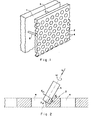
- the armour assembly according to the invention a fragment of which is shown in Fig- 1 comprises an inner armour plate 1 and an outer, perforated armour plate 2 held together by means of bars 3-
- the perforate plate 2 comprises a plurality of circular holes 4 evenly distributed thereover, the size of each hole 4 and the distances between the holes being within the range of the calibres of small-arms ammunition projectiles.
- the diameter of tholes 4 may be 11 mm and the distances between the holes about 5 mm; or, by another example, the diameter of the holes is 16 mm and the distances between the holes is about 8 mm.
- Armour plate 1 may be made of aluminium and be for example about 40 mm thick and the perforated armour plate 2 may be made of hardened steel and be about 8 mm thick.
- holes 4 are arranged in horizontal and vertical rows with the holes of each row in either direction being staggered with respect to a neighbouring row.
- holes 4 need not be circular and can instead be oval or polygonal.
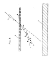
- Fig. 2 shows diagrammatically and to a larger scale the occurrences when a projectile 5 impinges upon the outer, perforated armour wall 2.
- the projectile arrives at a translatory velocity V in a trajectory which coincides with the vector V and at an angular velocity ⁇ .
- a braking force Fp When part of the surface of projectile 5 hits a metal part of wall 2 three different forces act on the impinging projectile 5, these being a braking force Fp, a first friction force F and a second friction force F ⁇ and these three forces give rise to turning moments whose effects will now be described with reference.to Fig. 3.
- an oncoming projectile 5 is shown in two positions, a first position in dashed lines showing it before it hits the outer, perforated plate 2 and a second position in drawn out lines showing the projectile after the passage across the perforated plate 2.
- the oncoming projectile 5 which approaches the perforated armour wall 2 at the velocity V is upon passage across wall 2 deflected from its original trajectory 6 to a new trajectory 7, the two trajectories forming between them an angle a so that trajectory 7 intersects the inner, armour plate 1 at a more acute angle than the original trajectory 6.
- two or more perforated walls of the kind of wall 2 may be associated with an inner armour wall 1, which may bear on or be distanced from each other.
- the armour assembly according to the invention also reduces the penetration power of a shaped charge projectile, this being due to the fact that the detonation occurs remote of wall 1 at the outer, perforated wall 2. While this will, as a rule, not totally prevent the penetration of a jet resulting from the shaped charge explosion, the spalling effect due to the shock wave inside the vehicle wall will be considerably reduced.
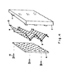
- a perforated armour plate 6 is associated with an ordinary inner missive armour plate 7 with the interposition of an intermediary corrugated and perforated metal sheet 8.
- brackets 9 and 10 For connecting an intermediary metal sheet 8 to both the outer perforated plate 6 and the inner metal plate 2 it comprises a plurality 0 1 brackets 9 and 10, the former facing plate 6 and the latter plate 7.
- plate 7 is provided with a plurality of brackets 11 each of which has a screw-threaded socket for cooperation with a screw-threaded male member 12.
- outer plates 6 are mounted on inner plates 7 with the interposition of intermediary metal sheets 8.
- each outer plate 1 is aligned with an inner plate 7 with interposition of an intermediary corrugated sheet 8 in such a manner that each bracket 9 of a corrugated sheet 8 is placed over one of the holes in plate 6 while, each bracket 10 of the corrugated sheet is caused to bear on a bracket 11 of plate 7.
- the perforated plate 6 and the intermediary, corrugated sheet 8 are secured to each other and to plate 7 by means of connecting screw-threaded male members such as threaded bolts or screws, some of which engage brackets 9 while others extend as far as plate 7 and engage a bracket 11 thereof.
- the embodiment of Fig. 4 has the advantage that by using a corrugated and perforated metal sheet for the connection of the outer and imer walls instead of braces, struts and the like the add-on weight is reduced and the deflecting effect is amplified.
- the add-on weight is about 40 kg/m 2
- the add-on weight may be reduced to 20 kg/m 2.
Landscapes
- Engineering & Computer Science (AREA)
- General Engineering & Computer Science (AREA)
- Ceramic Engineering (AREA)
- Aiming, Guidance, Guns With A Light Source, Armor, Camouflage, And Targets (AREA)
Applications Claiming Priority (4)
| Application Number | Priority Date | Filing Date | Title |
|---|---|---|---|
| IL8575633A IL75633A0 (en) | 1985-06-20 | 1985-06-20 | Armour assembly for armoured vehicles |
| IL75633 | 1985-06-20 | ||
| IL7722985 | 1985-12-04 | ||
| IL77229 | 1985-12-04 |
Publications (1)
| Publication Number | Publication Date |
|---|---|
| EP0209221A1 true EP0209221A1 (fr) | 1987-01-21 |
Family
ID=26321452
Family Applications (1)
| Application Number | Title | Priority Date | Filing Date |
|---|---|---|---|
| EP86303640A Withdrawn EP0209221A1 (fr) | 1985-06-20 | 1986-05-13 | Blindage pour véhicule |
Country Status (1)
| Country | Link |
|---|---|
| EP (1) | EP0209221A1 (fr) |
Cited By (20)
| Publication number | Priority date | Publication date | Assignee | Title |
|---|---|---|---|---|
| US4981067A (en) * | 1989-09-18 | 1991-01-01 | The United States Of America As Represented By The Secretary Of The Army | Reactived armor improvement |
| EP0402420A4 (en) * | 1988-03-01 | 1991-03-13 | General Dynamics Land Systems, Inc. | Armor plate having triangular holes |
| US5007326A (en) * | 1990-01-16 | 1991-04-16 | The United States Of America As Represented By The Secretary Of The Army | Cast single plate P900 armor |
| EP0403519A4 (en) * | 1988-03-01 | 1991-07-03 | General Dynamics Land Systems, Inc. | Perforated plate armor |
| US5214235A (en) * | 1992-03-25 | 1993-05-25 | The United States Of America As Represented By The United States Department Of Energy | Shock destruction armor system |
| US5221807A (en) * | 1989-12-06 | 1993-06-22 | Societe Europeenne De Propulsion | Ballistic protection armor |
| DE4344711A1 (de) * | 1993-12-27 | 1995-07-20 | Daimler Benz Ag | Schutzplatte |
| DE4418188A1 (de) * | 1994-05-25 | 1995-11-30 | Krauss Maffei Ag | Durchsehbare Panzerscheibe |
| FR2802630A1 (fr) * | 1989-09-14 | 2001-06-22 | France Etat | Blindage reactif, notamment pour la protection contre les projectiles fleches |
| EP1574810A1 (fr) * | 2004-03-11 | 2005-09-14 | PLASAN - Kibbutz Sasa | Blindage ballistique |
| EP1605224A3 (fr) * | 2004-06-03 | 2005-12-21 | Rafael Armament Development Authority Ltd. | Blindage passif qui comprend un élément de blindage en matériau fragile |
| EP1731870A1 (fr) * | 2005-06-09 | 2006-12-13 | Rafael-Armament Development Authority Ltd. | Système d'atténuation d'énergie et élément pour un tel système |
| WO2012028888A1 (fr) | 2010-09-02 | 2012-03-08 | Bae Systems Plc | Ensemble armure |
| GB2494643A (en) * | 2011-09-13 | 2013-03-20 | Mtl Group Ltd | Modular armour assembly unit |
| EP2198237A4 (fr) * | 2007-10-08 | 2013-04-10 | Bae Sys Land & Armaments Lp | Système de fenêtre blindée |
| DE102012100573A1 (de) * | 2012-01-24 | 2013-07-25 | Krauss-Maffei Wegmann Gmbh & Co. Kg | Schutzelement zum Schutz gegen ballistische Geschosse und militärisches Fahrzeug |
| EP3473965A1 (fr) | 2017-10-20 | 2019-04-24 | BAE SYSTEMS plc | Ensemble de blindage |
| WO2019077310A1 (fr) * | 2017-10-20 | 2019-04-25 | Bae Systems Plc | Ensemble blindage |
| CN110793397A (zh) * | 2019-11-12 | 2020-02-14 | 北京汽车集团越野车有限公司 | 一种防护装甲和具有其的车辆 |
| DE102020111534A1 (de) | 2020-04-28 | 2021-10-28 | Krauss-Maffei Wegmann Gmbh & Co. Kg | Panzerung |
Citations (4)
| Publication number | Priority date | Publication date | Assignee | Title |
|---|---|---|---|---|
| CH23749A (de) * | 1901-03-02 | 1902-09-15 | Adolph Leven | Einrichtung zum Schutz gegen Geschosse |
| FR50680E (fr) * | 1939-06-15 | 1941-02-20 | Dispositif de blindage | |
| FR909792A (fr) * | 1944-10-27 | 1946-05-17 | Perfectionnements aux blindages | |
| US2733177A (en) * | 1956-01-31 | meyer |
-
1986
- 1986-05-13 EP EP86303640A patent/EP0209221A1/fr not_active Withdrawn
Patent Citations (4)
| Publication number | Priority date | Publication date | Assignee | Title |
|---|---|---|---|---|
| US2733177A (en) * | 1956-01-31 | meyer | ||
| CH23749A (de) * | 1901-03-02 | 1902-09-15 | Adolph Leven | Einrichtung zum Schutz gegen Geschosse |
| FR50680E (fr) * | 1939-06-15 | 1941-02-20 | Dispositif de blindage | |
| FR909792A (fr) * | 1944-10-27 | 1946-05-17 | Perfectionnements aux blindages |
Cited By (28)
| Publication number | Priority date | Publication date | Assignee | Title |
|---|---|---|---|---|
| EP0402420A4 (en) * | 1988-03-01 | 1991-03-13 | General Dynamics Land Systems, Inc. | Armor plate having triangular holes |
| EP0403519A4 (en) * | 1988-03-01 | 1991-07-03 | General Dynamics Land Systems, Inc. | Perforated plate armor |
| FR2802630A1 (fr) * | 1989-09-14 | 2001-06-22 | France Etat | Blindage reactif, notamment pour la protection contre les projectiles fleches |
| US4981067A (en) * | 1989-09-18 | 1991-01-01 | The United States Of America As Represented By The Secretary Of The Army | Reactived armor improvement |
| US5221807A (en) * | 1989-12-06 | 1993-06-22 | Societe Europeenne De Propulsion | Ballistic protection armor |
| US5007326A (en) * | 1990-01-16 | 1991-04-16 | The United States Of America As Represented By The Secretary Of The Army | Cast single plate P900 armor |
| US5214235A (en) * | 1992-03-25 | 1993-05-25 | The United States Of America As Represented By The United States Department Of Energy | Shock destruction armor system |
| DE4344711A1 (de) * | 1993-12-27 | 1995-07-20 | Daimler Benz Ag | Schutzplatte |
| DE4418188A1 (de) * | 1994-05-25 | 1995-11-30 | Krauss Maffei Ag | Durchsehbare Panzerscheibe |
| EP1574810A1 (fr) * | 2004-03-11 | 2005-09-14 | PLASAN - Kibbutz Sasa | Blindage ballistique |
| US7513186B2 (en) | 2004-03-11 | 2009-04-07 | Plasan-Kibbutz Sasa | Ballistic armor |
| EP1605224A3 (fr) * | 2004-06-03 | 2005-12-21 | Rafael Armament Development Authority Ltd. | Blindage passif qui comprend un élément de blindage en matériau fragile |
| EP1731870A1 (fr) * | 2005-06-09 | 2006-12-13 | Rafael-Armament Development Authority Ltd. | Système d'atténuation d'énergie et élément pour un tel système |
| EP2198237A4 (fr) * | 2007-10-08 | 2013-04-10 | Bae Sys Land & Armaments Lp | Système de fenêtre blindée |
| WO2012028888A1 (fr) | 2010-09-02 | 2012-03-08 | Bae Systems Plc | Ensemble armure |
| AU2011298116B2 (en) * | 2010-09-02 | 2016-01-28 | Bae Systems Plc | Armour assembly |
| US9470481B2 (en) | 2010-09-02 | 2016-10-18 | Bae Systems Plc | Armor assembly |
| GB2501971A (en) * | 2010-09-02 | 2013-11-13 | Bae Systems Plc | Armour assembly |
| GB2494643A (en) * | 2011-09-13 | 2013-03-20 | Mtl Group Ltd | Modular armour assembly unit |
| GB2494643B (en) * | 2011-09-13 | 2015-02-11 | Mtl Group Ltd | Modular armour assembly unit |
| DE102012100573A1 (de) * | 2012-01-24 | 2013-07-25 | Krauss-Maffei Wegmann Gmbh & Co. Kg | Schutzelement zum Schutz gegen ballistische Geschosse und militärisches Fahrzeug |
| EP2807444B1 (fr) | 2012-01-24 | 2016-11-30 | Krauss-Maffei Wegmann GmbH & Co. KG | Élément de protection pour assurer une protection contre des projectiles balistiques et véhicule militaire |
| EP3128283B1 (fr) | 2012-01-24 | 2018-09-12 | Krauss-Maffei Wegmann GmbH & Co. KG | Élément de protection pour assurer une protection contre des projectiles balistiques et véhicule militaire |
| EP3473965A1 (fr) | 2017-10-20 | 2019-04-24 | BAE SYSTEMS plc | Ensemble de blindage |
| WO2019077310A1 (fr) * | 2017-10-20 | 2019-04-25 | Bae Systems Plc | Ensemble blindage |
| CN110793397A (zh) * | 2019-11-12 | 2020-02-14 | 北京汽车集团越野车有限公司 | 一种防护装甲和具有其的车辆 |
| DE102020111534A1 (de) | 2020-04-28 | 2021-10-28 | Krauss-Maffei Wegmann Gmbh & Co. Kg | Panzerung |
| DE102020111534B4 (de) * | 2020-04-28 | 2025-11-06 | Knds Deutschland Gmbh & Co. Kg | Panzerung |
Similar Documents
| Publication | Publication Date | Title |
|---|---|---|
| EP0209221A1 (fr) | Blindage pour véhicule | |
| US5070764A (en) | Combined reactive and passive armor | |
| US5866839A (en) | High performance armor protection system for tank crews and fighting vehicles | |
| EP0161390B1 (fr) | Eléments de blindage actif additionnel pour véhicules terrestres | |
| CA2747532C (fr) | Protection d'objet contre des charges creuses et procede de fabrication | |
| US4398446A (en) | Adjustable combat vehicle armor | |
| US5641933A (en) | Ballistic grill for special purpose vehicles | |
| EP2327950B1 (fr) | Coque en forme de W | |
| DE4440120C2 (de) | Schutzvorrichtung mit einer reaktiven Panzerung | |
| US5088416A (en) | Impact projectile | |
| EP2040024B1 (fr) | Module de blindage réactif | |
| US20110232472A1 (en) | Bar armor system for protecting against rocket-propelled grenades | |
| GB2375587A (en) | Armour panel | |
| US4957034A (en) | Candy cane configuration for modular armor unit | |
| US5003883A (en) | Lightweight blast shield | |
| US5402704A (en) | Armor for defeating kinetic energy projectiles | |
| US20220333907A1 (en) | Penetrator, use of a penetrator, and projectile | |
| DE2906378C1 (de) | Aktive Schutzvorrichtung fuer feste oder bewegliche Objekte | |
| DE19640991B4 (de) | Schutzvorrichtung für ein gepanzertes Fahrzeug | |
| DE69506024T2 (de) | Geschoss für Angriff gegen harte Ziele | |
| GB2329233A (en) | Reactive ballistic protection device | |
| EP1419359B1 (fr) | Dispositif de munition a deux charges | |
| EP3882563B1 (fr) | Projectile et procédé | |
| DE3636945B3 (de) | Aktive bzw. reaktive Panzerung | |
| EP3919852B1 (fr) | Véhicule avec protection anti-éclats |
Legal Events
| Date | Code | Title | Description |
|---|---|---|---|
| PUAI | Public reference made under article 153(3) epc to a published international application that has entered the european phase |
Free format text: ORIGINAL CODE: 0009012 |
|
| AK | Designated contracting states |
Kind code of ref document: A1 Designated state(s): AT BE CH DE FR GB IT LI LU NL SE |
|
| STAA | Information on the status of an ep patent application or granted ep patent |
Free format text: STATUS: THE APPLICATION IS DEEMED TO BE WITHDRAWN |
|
| 18D | Application deemed to be withdrawn |
Effective date: 19870722 |
|
| RIN1 | Information on inventor provided before grant (corrected) |
Inventor name: TARSI, YAMI Inventor name: ROSENBERG, GIDEON Inventor name: BEN-MOSHE, DAVID |