EP0209238A2 - Akustischer Doppelkolbenwandler mit auswählbarer Richtwirkung - Google Patents
Akustischer Doppelkolbenwandler mit auswählbarer Richtwirkung Download PDFInfo
- Publication number
- EP0209238A2 EP0209238A2 EP86304398A EP86304398A EP0209238A2 EP 0209238 A2 EP0209238 A2 EP 0209238A2 EP 86304398 A EP86304398 A EP 86304398A EP 86304398 A EP86304398 A EP 86304398A EP 0209238 A2 EP0209238 A2 EP 0209238A2
- Authority
- EP
- European Patent Office
- Prior art keywords
- transducer
- mass
- head
- active
- recited
- Prior art date
- Legal status (The legal status is an assumption and is not a legal conclusion. Google has not performed a legal analysis and makes no representation as to the accuracy of the status listed.)
- Withdrawn
Links
- 239000000463 material Substances 0.000 claims description 5
- 230000005855 radiation Effects 0.000 abstract description 25
- 239000000919 ceramic Substances 0.000 description 11
- 238000010276 construction Methods 0.000 description 5
- 230000035945 sensitivity Effects 0.000 description 5
- 239000011159 matrix material Substances 0.000 description 4
- 238000012986 modification Methods 0.000 description 4
- 230000004048 modification Effects 0.000 description 4
- 230000004044 response Effects 0.000 description 4
- 239000011149 active material Substances 0.000 description 3
- 238000000034 method Methods 0.000 description 3
- 229910000831 Steel Inorganic materials 0.000 description 2
- XAGFODPZIPBFFR-UHFFFAOYSA-N aluminium Chemical compound [Al] XAGFODPZIPBFFR-UHFFFAOYSA-N 0.000 description 2
- 229910052782 aluminium Inorganic materials 0.000 description 2
- 238000009472 formulation Methods 0.000 description 2
- 229910052451 lead zirconate titanate Inorganic materials 0.000 description 2
- HFGPZNIAWCZYJU-UHFFFAOYSA-N lead zirconate titanate Chemical compound [O-2].[O-2].[O-2].[O-2].[O-2].[Ti+4].[Zr+4].[Pb+2] HFGPZNIAWCZYJU-UHFFFAOYSA-N 0.000 description 2
- 239000000203 mixture Substances 0.000 description 2
- 239000010959 steel Substances 0.000 description 2
- 230000009466 transformation Effects 0.000 description 2
- RYGMFSIKBFXOCR-UHFFFAOYSA-N Copper Chemical compound [Cu] RYGMFSIKBFXOCR-UHFFFAOYSA-N 0.000 description 1
- 239000004593 Epoxy Substances 0.000 description 1
- 241000920033 Eugenes Species 0.000 description 1
- 239000000956 alloy Substances 0.000 description 1
- 229910045601 alloy Inorganic materials 0.000 description 1
- 238000013459 approach Methods 0.000 description 1
- 229910052790 beryllium Inorganic materials 0.000 description 1
- ATBAMAFKBVZNFJ-UHFFFAOYSA-N beryllium atom Chemical compound [Be] ATBAMAFKBVZNFJ-UHFFFAOYSA-N 0.000 description 1
- 239000003990 capacitor Substances 0.000 description 1
- 229910010293 ceramic material Inorganic materials 0.000 description 1
- 230000008859 change Effects 0.000 description 1
- 239000002131 composite material Substances 0.000 description 1
- 229910052802 copper Inorganic materials 0.000 description 1
- 239000010949 copper Substances 0.000 description 1
- 230000008030 elimination Effects 0.000 description 1
- 238000003379 elimination reaction Methods 0.000 description 1
- 230000005284 excitation Effects 0.000 description 1
- 238000003754 machining Methods 0.000 description 1
- -1 one-quarter hard Inorganic materials 0.000 description 1
- 230000026683 transduction Effects 0.000 description 1
- 238000010361 transduction Methods 0.000 description 1
- WFKWXMTUELFFGS-UHFFFAOYSA-N tungsten Chemical compound [W] WFKWXMTUELFFGS-UHFFFAOYSA-N 0.000 description 1
- 229910052721 tungsten Inorganic materials 0.000 description 1
- 239000010937 tungsten Substances 0.000 description 1
Images


Classifications
-
- B—PERFORMING OPERATIONS; TRANSPORTING
- B06—GENERATING OR TRANSMITTING MECHANICAL VIBRATIONS IN GENERAL
- B06B—METHODS OR APPARATUS FOR GENERATING OR TRANSMITTING MECHANICAL VIBRATIONS OF INFRASONIC, SONIC, OR ULTRASONIC FREQUENCY, e.g. FOR PERFORMING MECHANICAL WORK IN GENERAL
- B06B1/00—Methods or apparatus for generating mechanical vibrations of infrasonic, sonic, or ultrasonic frequency
- B06B1/02—Methods or apparatus for generating mechanical vibrations of infrasonic, sonic, or ultrasonic frequency making use of electrical energy
- B06B1/06—Methods or apparatus for generating mechanical vibrations of infrasonic, sonic, or ultrasonic frequency making use of electrical energy operating with piezoelectric effect or with electrostriction
- B06B1/0607—Methods or apparatus for generating mechanical vibrations of infrasonic, sonic, or ultrasonic frequency making use of electrical energy operating with piezoelectric effect or with electrostriction using multiple elements
- B06B1/0611—Methods or apparatus for generating mechanical vibrations of infrasonic, sonic, or ultrasonic frequency making use of electrical energy operating with piezoelectric effect or with electrostriction using multiple elements in a pile
- B06B1/0618—Methods or apparatus for generating mechanical vibrations of infrasonic, sonic, or ultrasonic frequency making use of electrical energy operating with piezoelectric effect or with electrostriction using multiple elements in a pile of piezo- and non-piezoelectric elements, e.g. 'Tonpilz'
Definitions
- the present invention relates to an electromechanical transducer and, more particularly, to a transducer type commonly known as a double piston transducer in which energy can be selectively radiated from opposite ends of the transducer device.
- a device commonly known as a double piston transducer is an electromechanical or electro- acoustical transducer known in the prior art.
- the device consists merely of a tnin piece of active material in contact with a radiating medium on both sides and which can be driven electrically to induce a planar motion therein.
- a flat disk or ring made of piezoelectric ceramic such as a lead zirconate titanate formulation
- This type of device is commonly operated at frequencies near its first longitudinal resonance frequency to achieve a higher output. To achieve a reasonably low resonance frequency and a well controlled response in a compact device, it is common practice to mass load the two sides of the active material with inactive material pieces.
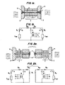
- FIG. 1(a) An example of a prior art mass loaded double piston transducer is shown in Fig. 1(a).
- Piezoelectric material rings 1 are bonded to form a composite piezoelectric stack 2 and electrically wired in parcel so that when a voltage is applied between the electrical loads, all of the individual rings 1 expand or contract in unison along the longitudinal axis of the device.
- head mass elements 3 At each end of the ceramic stack are bonded identical head mass elements 3 each having an outer face 4 which is in contact with the radiating medium 5.
- a stress rod or pretension bolt 6 and an associated nut 7 are used to join the components and to provide a compressive bias stress to the stack 2 of active elements.
- the electrodes which are positioned between the rings 1, and the insulating washers which are positioned at the ends of the stack 2 of rings are not shown. Such details are within the knowledge of the ordinarily skilled in the art.
- the device of Fig. 1(a) may be used as either a generator or receiver of mechanical or acoustic energy and is normally operated in a frequency band approximately centered on its primary resonance frequency. Tn this frequency band, the two head masses 3 move in opposite relative directions while the stack of active material 2 alternately expands and contracts along its length.
- the performance of the device in Fig. 1(a) can be approximated by the analogous behavior of the simplified electrical equivalent circuit of Fig. 1(b).
- the two inductors m h represent the two head masses, and the compliance of the ceramic stack is represented by the capacitor C.
- the two inductors m e1 and m e2 represent the effective mass contribution of the two ends of the ceramic stack 2.
- C o is the electrical clamped capacitance of the ceramic stack 2
- 0:1 is the transformation ratio of the electromechanical transformer representing the transduction property of the piezoelectric stack 2.
- the open boxes in the outer legs of the equivalent circuit represent the equivalent radiation impedance Z rad seen by the radiating faces of the transducer.
- the equivalent currents u, and u 2 in these impedances represent the velocities of the moving faces of the transducer.
- Tn an application requiring unidirectional radiation, it is possible to employ two separate devices each having only a single radiating face in contact with the medium 5.
- Fig. 2(a) where two identical longitudinal vibrator devices are mounted back to back. Eacn of these devices is similar to the double ended radiator except that it has only one head mass 3 in contact with the radiating medium. The second head mass is replaced by a tail mass 8 which is free to vibrate.
- the electrical equivalent circuits for this pair of devices are shown in Fig. 2(b).
- Each of tne two circuits is similar to the one circuit of Fig. 1(a) except for the replacement of one of the two equivalent head mass inductors m h by the equivalent inductance of the tail mass m t , and the elimination of the radiation impedance z rad in series with this equivalent tail inductance.
- the two transducers in this arrangement are separately driven, and each radiates in only one direction along their common longitudinal axis.
- the equivalent currents u and u 2 in the radiation impedances are completely independent.
- the two transducer arrangement is suitable for use in situations requiring unidirectional radiation.
- a disadvantage of this arrangement is that it is larger, heavier, more complex and more expensive than a single device which could fill the same function.
- It is an object of the present invention to provide a double piston transmitting transducer and a method of electrically driving the transducer wnicn together are capable of producing unidirectional radiation in either direction along the transducer longitudinal axis without significant radiation in the opposite direction.
- Tt is another object of the present invention to produce a device capable of changing the direction in which the radiation is projected from one end to the other without moving or rotating the transducer.
- the oresent invention achieves the above objects by the addition of an extra mass placed in the center of the piezoelectric stack of a double piston transducer and appropriate electrical drive or receive circuitry connected to the two ceramic stacks thus created.
- the extra mass divides the stack into two separate stacks which are not connected electrically, although the individual ceramic rings in each stack are electrically connected in parallel as in the prior art devices.
- the present invention achieves selectable unidirectional response in a double piston transducer element by including an additional mass in the center of the piezoelectric stack, and by appropriate driving of the two ceramic stacks thus created.
- Fig. 3(a) illustrates a double ended transducer with an extra mass 9, which will hereafter be called the center mass.
- the center mass 9 is positioned between active transducer stacks 2' and 2" and head masses 3' and 3".
- the active stacks 2' and 2" are compressively biased by stress rods 6' and 6" and nuts 7' and 7".
- the center mass 9 allows vibration to be transferred between the stacks 2' and 2" and the masses 3' and 3".
- the transferred vibration can enhance the vibration on the opposite side, nullify the vibration on the opposite side or any combination in between.
- the two head masses 3' and 3" may be of identical construction as is the case for the head masses 3 of the prior art device, or they may be different to provide differing radiation properties to the two sides of the device.
- the two active stacks 2' and 2" may be identical materials or they may be different to tailor the response in the two directions.
- the transducer of Fig. 3(a) is assembled in a manner substantially identical to the assembly of one of the prior art transducers of Fig. 2(a).
- the active transducer elements 1 can be piezoelectric elements manufactured from a piezoelectric ceramic material, such as a lead zirconate titanate formulation and can be obtainea from Vernitron, Inc. in Bedford, Ohio.
- the head masses 3' and 3" and center mass 9 can be tungsten, steel or aluminum.
- Stress rods 6' and 6" can be a copper beryllium, one-quarter hard, alloy No. 172 in accordance with ASTM B-196 artifically aged to obtain Rockwell C39-42 after machining.
- the nuts 7' and 7" can be of aluminum or steel, but must have a flat surface against the head masses 3' and 3" so that no rocking of the nuts occur.
- the entire transducer can be assembled either by using epoxy and then tensioning the stress rods 6' and 6" or loosely assembled and held together by the stress rods 6' and 6". The adjustment of the compressive bias using the stress rods 6' and 6" is within the ordinary skill in the art.
- Other features of typical transducers such as insulating washers, wiring, electrical contacts etc. are well known to those of ordinary skill in the art and can be found in, for example, U.S. Patent No. 3,309,654 to Miller.
- the solid lines of the stress rods 5' and 6" in Fig. 3(a) indicate the rods 6' and 6" are fixed to the respective head masses 3' and 3" and to the center mass 9. However, it is possible to have a single stress rod connecting the two head masses 3' and 3" and passing through a hole in the center mass 9. The extension of the single rod through the center mass 9 is illustrated by the dashed lines in Fig. 3(a).
- FIG. 3(b) The simplified equivalent circuit representation for the transducer of Fig. 3(a) is shown in Fig. 3(b).
- This circuit includes two piezoelectric stacks, each of which is represented by the combination of the equivalent electrical components C 0 , C 1 , C 2 , m 1 , m 2 , m e1 ' m e1 and the electromechanical transformer whose transformation ratio is ⁇ .
- the equivalent inductor m c in the circuit represents the center mass 9.
- the equivalent circuit of Fig. 3(b) makes it evident that the transducer device of Fig. 3(a) may be viewed and analyzed as a two input, two output linear system. Tf the device is used as a transmitting transducer, the input parameters are the voltage E 1 and E 2 at the electrical connections to the two ceramic stacks 2, and the output parameters are the velocities u 1 and u 2 of the two radiating head masses 3.
- the electroacoustic transfer matrix for the element can be represented as: where u 1 and u 2 are tne velocities of head masses 3' and 3" respectively, and E 1 and E 2 are' the drive voltages applied to ceramic stacks 2' and 2", respectively, and c 11 -c 22 represent transfer matrix elements.
- the transfer elements C 11 -C 22 are determined as follows: where w is the angular frequency of operating and w+2 f where f is the operating frequency.
- equation (1) allows the calculation of the two complex stack voltages which will produce them. In order to constrain u ? to zero, these equations can readily be used to show that the required ratio of drive voltages is
- equation (11) provides high power acoustic radiation from the head mass 3' and no radiation from the head 3".
- equation (1) may be used to provide high radiation from head 3" and no radiation for head 3' with an applied voltage ratio of
- Fig. 4 shows a representative configuration for the transducer and driving electronics to provide the performance possibilities discussed above.
- This figure shows an electrical signal generator 11 which provides the system input.
- This signal is sent through the independent channels of gain and phase adjustment units 12 which adjust the amplitude and phase of the input signal in accordance with the desired complex drive voltage E for each channel.
- the complex drive voltages are applied to power amplifiers 13, amplified and then applied to the two piezoelectric stacks of the transducer 14 of Fig. 3(a).
- Fig. 5 is an example of the use of the new device as a receiving sensor.
- the electrical signals produced in the two piezoelectric stacks are buffered and amplified by separate preamplifiers 19.
- the preamp output signals are then fed to separate gain and phase adjustment circuitry whose effect on the signals can be manually or automatically adjusted to provide the proper directional response for the system in accordance with equation (1).
- These signals are then added togetner in a summing circuit 20 to provide a final output signal 21 having the desired directional sensitivity.
- the transducer device is symmetric about the center mass 9.
- the center mass 9 should be at least as massive as one of the head masses 3' or 3".
- the center mass 9 should be as massive as the most massive of the head masses 3' and 3".
- An additional alternative embodiment of the present invention can achieve further performance enhancement in some applications by providing somewhat different dimensions and/or materials for the left and right transducer elements.
- the effect of sucn modifications can be determined by substituting the desired values into equation (1) as represented by Fig. 3(b). Modifications of this type could allow the rightward and leftward radiation to be optimized for somewhat different operating frequency bands, and thus increase the total operating bandwidth of the transmitting system.
Landscapes
- Engineering & Computer Science (AREA)
- Mechanical Engineering (AREA)
- Transducers For Ultrasonic Waves (AREA)
- Piezo-Electric Transducers For Audible Bands (AREA)
- Measurement Of Velocity Or Position Using Acoustic Or Ultrasonic Waves (AREA)
Applications Claiming Priority (2)
| Application Number | Priority Date | Filing Date | Title |
|---|---|---|---|
| US74518485A | 1985-06-14 | 1985-06-14 | |
| US745184 | 1985-06-14 |
Publications (2)
| Publication Number | Publication Date |
|---|---|
| EP0209238A2 true EP0209238A2 (de) | 1987-01-21 |
| EP0209238A3 EP0209238A3 (de) | 1989-03-08 |
Family
ID=24995604
Family Applications (1)
| Application Number | Title | Priority Date | Filing Date |
|---|---|---|---|
| EP86304398A Withdrawn EP0209238A3 (de) | 1985-06-14 | 1986-06-10 | Akustischer Doppelkolbenwandler mit auswählbarer Richtwirkung |
Country Status (2)
| Country | Link |
|---|---|
| EP (1) | EP0209238A3 (de) |
| JP (1) | JPS61289800A (de) |
Cited By (11)
| Publication number | Priority date | Publication date | Assignee | Title |
|---|---|---|---|---|
| FR2664118A1 (fr) * | 1990-06-29 | 1992-01-03 | Thomson Csf | Transducteur acoustique bi-frequence et son utilisation pour la realisation d'une antenne acoustique basse-frequence. |
| FR2665998A1 (fr) * | 1988-05-05 | 1992-02-21 | France Etat Armement | Procedes et transducteurs electro-acoustiques pour emettre des ondes acoustiques a basse frequence dans un liquide. |
| FR2688112A1 (fr) * | 1988-04-28 | 1993-09-03 | France Etat Armement | Transducteurs electro-acoustiques directifs comportant une coque etanche en deux parties. |
| FR2688972A1 (fr) * | 1988-04-28 | 1993-09-24 | France Etat Armement | Transducteurs electro-acoustiques comportant une coque emettrice flexible et etanche. |
| FR2720586A1 (fr) * | 1994-05-26 | 1995-12-01 | France Etat Armement | Antenne sonar à têtes démontables. |
| EP0809920A4 (de) * | 1995-02-17 | 1999-11-03 | Bolt Beranek & Newman | Akustischer unterwassersender |
| FR2779533A1 (fr) * | 1998-06-09 | 1999-12-10 | Total Sa | Dispositif d'acquisition sismique a haute resolution |
| EP1060798A1 (de) * | 1999-06-18 | 2000-12-20 | Prokic Miodrag | Einkolben Ultraschallrichtwandler |
| DE10027264C5 (de) * | 2000-05-31 | 2004-10-28 | Dr. Hielscher Gmbh | Ultraschallwandler |
| WO2017039964A1 (en) * | 2015-09-04 | 2017-03-09 | Motorola Solutions, Inc. | Ultrasonic transmitter |
| CN112630754A (zh) * | 2020-11-24 | 2021-04-09 | 海鹰企业集团有限责任公司 | 换能器指向性波束发生装置、检测系统及其检测方法 |
Families Citing this family (1)
| Publication number | Priority date | Publication date | Assignee | Title |
|---|---|---|---|---|
| JP4983171B2 (ja) | 2005-11-15 | 2012-07-25 | セイコーエプソン株式会社 | 静電型トランスデューサ、容量性負荷の駆動回路、回路定数の設定方法、超音波スピーカ、および指向性音響システム |
Family Cites Families (3)
| Publication number | Priority date | Publication date | Assignee | Title |
|---|---|---|---|---|
| US3309654A (en) * | 1965-09-02 | 1967-03-14 | Gen Dynamics Corp | Acoustic apparatus |
| FR2302656A1 (fr) * | 1975-02-27 | 1976-09-24 | France Etat | Transducteur piezoelectrique pour basses frequences |
| JPS59230399A (ja) * | 1983-06-14 | 1984-12-24 | Tech Res & Dev Inst Of Japan Def Agency | 圧電振動子 |
-
1986
- 1986-06-10 EP EP86304398A patent/EP0209238A3/de not_active Withdrawn
- 1986-06-13 JP JP13638486A patent/JPS61289800A/ja active Pending
Cited By (20)
| Publication number | Priority date | Publication date | Assignee | Title |
|---|---|---|---|---|
| FR2688112A1 (fr) * | 1988-04-28 | 1993-09-03 | France Etat Armement | Transducteurs electro-acoustiques directifs comportant une coque etanche en deux parties. |
| FR2688972A1 (fr) * | 1988-04-28 | 1993-09-24 | France Etat Armement | Transducteurs electro-acoustiques comportant une coque emettrice flexible et etanche. |
| FR2665998A1 (fr) * | 1988-05-05 | 1992-02-21 | France Etat Armement | Procedes et transducteurs electro-acoustiques pour emettre des ondes acoustiques a basse frequence dans un liquide. |
| FR2664118A1 (fr) * | 1990-06-29 | 1992-01-03 | Thomson Csf | Transducteur acoustique bi-frequence et son utilisation pour la realisation d'une antenne acoustique basse-frequence. |
| FR2720586A1 (fr) * | 1994-05-26 | 1995-12-01 | France Etat Armement | Antenne sonar à têtes démontables. |
| EP0809920A4 (de) * | 1995-02-17 | 1999-11-03 | Bolt Beranek & Newman | Akustischer unterwassersender |
| US6366536B1 (en) | 1998-06-09 | 2002-04-02 | Total Fina Elf S.A. | High-resolution seismic acquisition device |
| WO1999064897A1 (fr) * | 1998-06-09 | 1999-12-16 | Total Fina Elf S.A. | Dispositif d'acquisition sismique a haute resolution |
| GB2357843A (en) * | 1998-06-09 | 2001-07-04 | Total Fina Elf | High-resolution seismic acquisition device |
| FR2779533A1 (fr) * | 1998-06-09 | 1999-12-10 | Total Sa | Dispositif d'acquisition sismique a haute resolution |
| GB2357843B (en) * | 1998-06-09 | 2002-07-24 | Total Fina Elf | High - resolution seismic acquisition device |
| EP1060798A1 (de) * | 1999-06-18 | 2000-12-20 | Prokic Miodrag | Einkolben Ultraschallrichtwandler |
| DE10027264C5 (de) * | 2000-05-31 | 2004-10-28 | Dr. Hielscher Gmbh | Ultraschallwandler |
| WO2017039964A1 (en) * | 2015-09-04 | 2017-03-09 | Motorola Solutions, Inc. | Ultrasonic transmitter |
| GB2556300A (en) * | 2015-09-04 | 2018-05-23 | Motorola Solutions Inc | Ultrasonic transmitter |
| US10065212B2 (en) | 2015-09-04 | 2018-09-04 | Motorola Solutions, Inc. | Ultrasonic transmitter |
| GB2556300B (en) * | 2015-09-04 | 2021-10-20 | Motorola Solutions Inc | Ultrasonic transmitter |
| DE112016004023B4 (de) | 2015-09-04 | 2022-03-03 | Motorola Solutions, Inc. | Ultraschallsender und verfahren zur erzeugung einer ultraschallwelle durch einen ultraschallsender |
| CN112630754A (zh) * | 2020-11-24 | 2021-04-09 | 海鹰企业集团有限责任公司 | 换能器指向性波束发生装置、检测系统及其检测方法 |
| CN112630754B (zh) * | 2020-11-24 | 2024-06-25 | 海鹰企业集团有限责任公司 | 换能器指向性波束发生装置、检测系统及其检测方法 |
Also Published As
| Publication number | Publication date |
|---|---|
| JPS61289800A (ja) | 1986-12-19 |
| EP0209238A3 (de) | 1989-03-08 |
Similar Documents
| Publication | Publication Date | Title |
|---|---|---|
| EP0169727B1 (de) | Breitbandiger Radialschwingungswandler | |
| US4845688A (en) | Electro-mechanical transduction apparatus | |
| US4996674A (en) | Double piston acoustic transducer with selectable directivity | |
| US4754441A (en) | Directional flextensional transducer | |
| US4072871A (en) | Electroacoustic transducer | |
| EP0209238A2 (de) | Akustischer Doppelkolbenwandler mit auswählbarer Richtwirkung | |
| US5546946A (en) | Ultrasonic diagnostic transducer array with elevation focus | |
| US4635484A (en) | Ultrasonic transducer system | |
| US4051455A (en) | Double flexure disc electro-acoustic transducer | |
| US6950373B2 (en) | Multiply resonant wideband transducer apparatus | |
| US2895061A (en) | Piezoelectric sandwich transducer | |
| EP0835462A1 (de) | Elektrodynamische antriebsmittel für akustische sendern | |
| Butler et al. | A broadband hybrid magnetostrictive/piezoelectric transducer array | |
| US4709360A (en) | Hydrophone transducer with negative feedback system | |
| WO2002019388A2 (en) | Class v flextensional transducer with directional beam patterns | |
| US5515342A (en) | Dual frequency sonar transducer assembly | |
| US4972390A (en) | Stack driven flexural disc transducer | |
| US3110825A (en) | Folded transducer | |
| Butler | Triply resonant broadband transducers | |
| EP1060798A1 (de) | Einkolben Ultraschallrichtwandler | |
| US3497731A (en) | Bender type transducers | |
| US6822373B1 (en) | Broadband triple resonant transducer | |
| US5867450A (en) | State switched acoustic transducer | |
| US5101384A (en) | Acoustic devices | |
| US3309654A (en) | Acoustic apparatus |
Legal Events
| Date | Code | Title | Description |
|---|---|---|---|
| PUAI | Public reference made under article 153(3) epc to a published international application that has entered the european phase |
Free format text: ORIGINAL CODE: 0009012 |
|
| AK | Designated contracting states |
Kind code of ref document: A2 Designated state(s): FR GB IT |
|
| PUAL | Search report despatched |
Free format text: ORIGINAL CODE: 0009013 |
|
| AK | Designated contracting states |
Kind code of ref document: A3 Designated state(s): FR GB IT |
|
| STAA | Information on the status of an ep patent application or granted ep patent |
Free format text: STATUS: THE APPLICATION IS DEEMED TO BE WITHDRAWN |
|
| 18D | Application deemed to be withdrawn |
Effective date: 19890909 |
|
| RIN1 | Information on inventor provided before grant (corrected) |
Inventor name: THOMPSON, STEPHEN CC. |