EP0209307A1 - Reinigung von Metallgegenständen - Google Patents
Reinigung von Metallgegenständen Download PDFInfo
- Publication number
- EP0209307A1 EP0209307A1 EP86305244A EP86305244A EP0209307A1 EP 0209307 A1 EP0209307 A1 EP 0209307A1 EP 86305244 A EP86305244 A EP 86305244A EP 86305244 A EP86305244 A EP 86305244A EP 0209307 A1 EP0209307 A1 EP 0209307A1
- Authority
- EP
- European Patent Office
- Prior art keywords
- halide
- cleaning process
- article
- reaction vessel
- reactive atmosphere
- Prior art date
- Legal status (The legal status is an assumption and is not a legal conclusion. Google has not performed a legal analysis and makes no representation as to the accuracy of the status listed.)
- Granted
Links
- 238000004140 cleaning Methods 0.000 title claims description 60
- 229910052751 metal Inorganic materials 0.000 title description 10
- 239000002184 metal Substances 0.000 title description 10
- 238000000034 method Methods 0.000 claims abstract description 74
- 230000008569 process Effects 0.000 claims abstract description 68
- 239000012298 atmosphere Substances 0.000 claims abstract description 38
- 150000004820 halides Chemical class 0.000 claims abstract description 32
- 229910000601 superalloy Inorganic materials 0.000 claims abstract description 25
- XPDWGBQVDMORPB-UHFFFAOYSA-N Fluoroform Chemical compound FC(F)F XPDWGBQVDMORPB-UHFFFAOYSA-N 0.000 claims abstract description 21
- 239000001257 hydrogen Substances 0.000 claims abstract description 20
- 229910052739 hydrogen Inorganic materials 0.000 claims abstract description 20
- 238000011109 contamination Methods 0.000 claims abstract description 19
- UFHFLCQGNIYNRP-UHFFFAOYSA-N Hydrogen Chemical compound [H][H] UFHFLCQGNIYNRP-UHFFFAOYSA-N 0.000 claims abstract description 17
- 230000007797 corrosion Effects 0.000 claims abstract description 10
- 238000005260 corrosion Methods 0.000 claims abstract description 10
- 239000011261 inert gas Substances 0.000 claims abstract description 5
- 238000001514 detection method Methods 0.000 claims abstract description 3
- 238000005530 etching Methods 0.000 claims abstract description 3
- 238000006243 chemical reaction Methods 0.000 claims description 50
- 239000000376 reactant Substances 0.000 claims description 30
- XKRFYHLGVUSROY-UHFFFAOYSA-N Argon Chemical compound [Ar] XKRFYHLGVUSROY-UHFFFAOYSA-N 0.000 claims description 22
- PXHVJJICTQNCMI-UHFFFAOYSA-N Nickel Chemical compound [Ni] PXHVJJICTQNCMI-UHFFFAOYSA-N 0.000 claims description 19
- 229910052786 argon Inorganic materials 0.000 claims description 11
- 239000000203 mixture Substances 0.000 claims description 11
- 238000010438 heat treatment Methods 0.000 claims description 10
- 229910052759 nickel Inorganic materials 0.000 claims description 8
- 239000010941 cobalt Substances 0.000 claims description 6
- 229910017052 cobalt Inorganic materials 0.000 claims description 6
- GUTLYIVDDKVIGB-UHFFFAOYSA-N cobalt atom Chemical compound [Co] GUTLYIVDDKVIGB-UHFFFAOYSA-N 0.000 claims description 6
- 238000011049 filling Methods 0.000 claims description 4
- 150000002431 hydrogen Chemical class 0.000 claims description 4
- 125000004122 cyclic group Chemical group 0.000 claims description 3
- 230000000063 preceeding effect Effects 0.000 claims 2
- 230000000717 retained effect Effects 0.000 claims 2
- 238000011084 recovery Methods 0.000 claims 1
- 230000000007 visual effect Effects 0.000 claims 1
- 230000003647 oxidation Effects 0.000 abstract description 2
- 238000007254 oxidation reaction Methods 0.000 abstract description 2
- 239000007789 gas Substances 0.000 description 37
- 239000000463 material Substances 0.000 description 15
- 238000012360 testing method Methods 0.000 description 14
- 230000008439 repair process Effects 0.000 description 11
- KRHYYFGTRYWZRS-UHFFFAOYSA-M Fluoride anion Chemical compound [F-] KRHYYFGTRYWZRS-UHFFFAOYSA-M 0.000 description 9
- 239000000843 powder Substances 0.000 description 9
- 238000001000 micrograph Methods 0.000 description 8
- 239000011651 chromium Substances 0.000 description 7
- 238000000576 coating method Methods 0.000 description 7
- VYZAMTAEIAYCRO-UHFFFAOYSA-N Chromium Chemical compound [Cr] VYZAMTAEIAYCRO-UHFFFAOYSA-N 0.000 description 6
- XEEYBQQBJWHFJM-UHFFFAOYSA-N Iron Chemical compound [Fe] XEEYBQQBJWHFJM-UHFFFAOYSA-N 0.000 description 6
- 230000009471 action Effects 0.000 description 5
- 229910045601 alloy Inorganic materials 0.000 description 5
- 239000000956 alloy Substances 0.000 description 5
- 229920001343 polytetrafluoroethylene Polymers 0.000 description 5
- 238000005266 casting Methods 0.000 description 4
- 229910052804 chromium Inorganic materials 0.000 description 4
- 229910021563 chromium fluoride Inorganic materials 0.000 description 4
- 239000011248 coating agent Substances 0.000 description 4
- -1 fluoride compound Chemical class 0.000 description 4
- 239000004810 polytetrafluoroethylene Substances 0.000 description 4
- FTBATIJJKIIOTP-UHFFFAOYSA-K trifluorochromium Chemical compound F[Cr](F)F FTBATIJJKIIOTP-UHFFFAOYSA-K 0.000 description 4
- 230000007547 defect Effects 0.000 description 3
- 229910052742 iron Inorganic materials 0.000 description 3
- 230000035485 pulse pressure Effects 0.000 description 3
- 239000010936 titanium Substances 0.000 description 3
- 238000003466 welding Methods 0.000 description 3
- PNEYBMLMFCGWSK-UHFFFAOYSA-N aluminium oxide Inorganic materials [O-2].[O-2].[O-2].[Al+3].[Al+3] PNEYBMLMFCGWSK-UHFFFAOYSA-N 0.000 description 2
- 230000003466 anti-cipated effect Effects 0.000 description 2
- 239000012300 argon atmosphere Substances 0.000 description 2
- 238000005219 brazing Methods 0.000 description 2
- POIUWJQBRNEFGX-XAMSXPGMSA-N cathelicidin Chemical compound C([C@@H](C(=O)N[C@@H](CCCNC(N)=N)C(=O)N[C@@H](CCCCN)C(=O)N[C@@H](CO)C(=O)N[C@@H](CCCCN)C(=O)N[C@@H](CCC(O)=O)C(=O)N[C@@H](CCCCN)C(=O)N[C@@H]([C@@H](C)CC)C(=O)NCC(=O)N[C@@H](CCCCN)C(=O)N[C@@H](CCC(O)=O)C(=O)N[C@@H](CC=1C=CC=CC=1)C(=O)N[C@@H](CCCCN)C(=O)N[C@@H](CCCNC(N)=N)C(=O)N[C@@H]([C@@H](C)CC)C(=O)N[C@@H](C(C)C)C(=O)N[C@@H](CCC(N)=O)C(=O)N[C@@H](CCCNC(N)=N)C(=O)N[C@@H]([C@@H](C)CC)C(=O)N[C@@H](CCCCN)C(=O)N[C@@H](CC(O)=O)C(=O)N[C@@H](CC=1C=CC=CC=1)C(=O)N[C@@H](CC(C)C)C(=O)N[C@@H](CCCNC(N)=N)C(=O)N[C@@H](CC(N)=O)C(=O)N[C@@H](CC(C)C)C(=O)N[C@@H](C(C)C)C(=O)N1[C@@H](CCC1)C(=O)N[C@@H](CCCNC(N)=N)C(=O)N[C@@H]([C@@H](C)O)C(=O)N[C@@H](CCC(O)=O)C(=O)N[C@@H](CO)C(O)=O)NC(=O)[C@H](CC=1C=CC=CC=1)NC(=O)[C@H](CC(O)=O)NC(=O)CNC(=O)[C@H](CC(C)C)NC(=O)[C@@H](N)CC(C)C)C1=CC=CC=C1 POIUWJQBRNEFGX-XAMSXPGMSA-N 0.000 description 2
- 238000001816 cooling Methods 0.000 description 2
- 238000009792 diffusion process Methods 0.000 description 2
- 230000000694 effects Effects 0.000 description 2
- 150000002222 fluorine compounds Chemical class 0.000 description 2
- 238000002955 isolation Methods 0.000 description 2
- 238000004519 manufacturing process Methods 0.000 description 2
- 229910044991 metal oxide Inorganic materials 0.000 description 2
- 150000004706 metal oxides Chemical class 0.000 description 2
- 238000012545 processing Methods 0.000 description 2
- 239000000047 product Substances 0.000 description 2
- 230000009467 reduction Effects 0.000 description 2
- 239000000126 substance Substances 0.000 description 2
- 238000010301 surface-oxidation reaction Methods 0.000 description 2
- 230000007723 transport mechanism Effects 0.000 description 2
- VEXZGXHMUGYJMC-UHFFFAOYSA-M Chloride anion Chemical compound [Cl-] VEXZGXHMUGYJMC-UHFFFAOYSA-M 0.000 description 1
- 238000012369 In process control Methods 0.000 description 1
- 229910000831 Steel Inorganic materials 0.000 description 1
- RTAQQCXQSZGOHL-UHFFFAOYSA-N Titanium Chemical compound [Ti] RTAQQCXQSZGOHL-UHFFFAOYSA-N 0.000 description 1
- SLTNJGDECJATET-RIVJSTIKSA-N [(8r,9s,10r,13s,14s,17s)-10,13-dimethyl-3-oxo-1,2,6,7,8,9,11,12,14,15,16,17-dodecahydrocyclopenta[a]phenanthren-17-yl] 4-methylpentanoate;[(8r,9s,10r,13s,14s,17s)-10,13-dimethyl-3-oxo-1,2,6,7,8,9,11,12,14,15,16,17-dodecahydrocyclopenta[a]phenanthren-17-yl Chemical compound C1CC2=CC(=O)CC[C@]2(C)[C@@H]2[C@@H]1[C@@H]1CC[C@H](OC(=O)CC)[C@@]1(C)CC2.C1CC2=CC(=O)CC[C@]2(C)[C@@H]2[C@@H]1[C@@H]1CC[C@H](OC(=O)CCC(C)C)[C@@]1(C)CC2.C([C@]1(C2CC[C@@H]1O)C)CC(C1=CC=3)C2CCC1=CC=3OC(=O)C1=CC=CC=C1.O([C@H]1CCC2C3C(C4=CC=C(O)C=C4CC3)CC[C@@]21C)C(=O)CCC1=CC=CC=C1.O([C@H]1CC[C@H]2[C@H]3[C@@H]([C@]4(CCC(=O)C=C4CC3)C)CC[C@@]21C)C(=O)CCC1=CC=CC=C1 SLTNJGDECJATET-RIVJSTIKSA-N 0.000 description 1
- 238000005270 abrasive blasting Methods 0.000 description 1
- 239000004411 aluminium Substances 0.000 description 1
- 229910052782 aluminium Inorganic materials 0.000 description 1
- XAGFODPZIPBFFR-UHFFFAOYSA-N aluminium Chemical compound [Al] XAGFODPZIPBFFR-UHFFFAOYSA-N 0.000 description 1
- 230000008901 benefit Effects 0.000 description 1
- 230000015556 catabolic process Effects 0.000 description 1
- 239000007795 chemical reaction product Substances 0.000 description 1
- 238000005229 chemical vapour deposition Methods 0.000 description 1
- 150000001805 chlorine compounds Chemical class 0.000 description 1
- 230000000052 comparative effect Effects 0.000 description 1
- 238000009833 condensation Methods 0.000 description 1
- 230000005494 condensation Effects 0.000 description 1
- 238000005112 continuous flow technique Methods 0.000 description 1
- 239000000498 cooling water Substances 0.000 description 1
- 238000005336 cracking Methods 0.000 description 1
- 238000000354 decomposition reaction Methods 0.000 description 1
- 230000007812 deficiency Effects 0.000 description 1
- 230000002950 deficient Effects 0.000 description 1
- 238000006731 degradation reaction Methods 0.000 description 1
- 239000003085 diluting agent Substances 0.000 description 1
- 238000004453 electron probe microanalysis Methods 0.000 description 1
- 238000005516 engineering process Methods 0.000 description 1
- 230000005496 eutectics Effects 0.000 description 1
- 230000008020 evaporation Effects 0.000 description 1
- 238000001704 evaporation Methods 0.000 description 1
- 238000002474 experimental method Methods 0.000 description 1
- 229920002313 fluoropolymer Polymers 0.000 description 1
- 239000011888 foil Substances 0.000 description 1
- 229910052735 hafnium Inorganic materials 0.000 description 1
- VBJZVLUMGGDVMO-UHFFFAOYSA-N hafnium atom Chemical compound [Hf] VBJZVLUMGGDVMO-UHFFFAOYSA-N 0.000 description 1
- 229910052736 halogen Inorganic materials 0.000 description 1
- 150000002367 halogens Chemical class 0.000 description 1
- 238000010965 in-process control Methods 0.000 description 1
- 238000011065 in-situ storage Methods 0.000 description 1
- 150000002484 inorganic compounds Chemical class 0.000 description 1
- 238000005259 measurement Methods 0.000 description 1
- 229910001512 metal fluoride Inorganic materials 0.000 description 1
- 238000002156 mixing Methods 0.000 description 1
- 229910001235 nimonic Inorganic materials 0.000 description 1
- 239000010955 niobium Substances 0.000 description 1
- 229910052758 niobium Inorganic materials 0.000 description 1
- GUCVJGMIXFAOAE-UHFFFAOYSA-N niobium atom Chemical compound [Nb] GUCVJGMIXFAOAE-UHFFFAOYSA-N 0.000 description 1
- 238000000879 optical micrograph Methods 0.000 description 1
- 150000002894 organic compounds Chemical class 0.000 description 1
- 230000035515 penetration Effects 0.000 description 1
- 229920000642 polymer Polymers 0.000 description 1
- 238000003908 quality control method Methods 0.000 description 1
- 238000004064 recycling Methods 0.000 description 1
- 238000004626 scanning electron microscopy Methods 0.000 description 1
- 238000007789 sealing Methods 0.000 description 1
- 239000007787 solid Substances 0.000 description 1
- 239000010935 stainless steel Substances 0.000 description 1
- 229910001220 stainless steel Inorganic materials 0.000 description 1
- 239000010959 steel Substances 0.000 description 1
- 239000000758 substrate Substances 0.000 description 1
- 229910052719 titanium Inorganic materials 0.000 description 1
- 231100000331 toxic Toxicity 0.000 description 1
- 230000002588 toxic effect Effects 0.000 description 1
- 238000012546 transfer Methods 0.000 description 1
- 239000002699 waste material Substances 0.000 description 1
- XLYOFNOQVPJJNP-UHFFFAOYSA-N water Substances O XLYOFNOQVPJJNP-UHFFFAOYSA-N 0.000 description 1
- 238000009736 wetting Methods 0.000 description 1
- 229910052727 yttrium Inorganic materials 0.000 description 1
- VWQVUPCCIRVNHF-UHFFFAOYSA-N yttrium atom Chemical compound [Y] VWQVUPCCIRVNHF-UHFFFAOYSA-N 0.000 description 1
Images

Classifications
-
- C—CHEMISTRY; METALLURGY
- C23—COATING METALLIC MATERIAL; COATING MATERIAL WITH METALLIC MATERIAL; CHEMICAL SURFACE TREATMENT; DIFFUSION TREATMENT OF METALLIC MATERIAL; COATING BY VACUUM EVAPORATION, BY SPUTTERING, BY ION IMPLANTATION OR BY CHEMICAL VAPOUR DEPOSITION, IN GENERAL; INHIBITING CORROSION OF METALLIC MATERIAL OR INCRUSTATION IN GENERAL
- C23G—CLEANING OR DE-GREASING OF METALLIC MATERIAL BY CHEMICAL METHODS OTHER THAN ELECTROLYSIS
- C23G5/00—Cleaning or de-greasing metallic material by other methods; Apparatus for cleaning or de-greasing metallic material with organic solvents
Definitions
- the present invention relates to the cleaning of metal articles for the removal of surface oxidation and other corrosion contamination. It is especially but not solely of application to the cleaning of iron, nickel or cobalt based superalloy gas turbine engine components.
- the invention also relates to etch treatment of iron, nickel or cobalt based superalloy articles in manufacture for the detection of flaws therein.
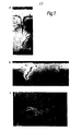
- Figure 1 of the drawings shows three micrographs A,B and C, of inadequate braze repairs made to superalloy engine components in consequence of insufficient removal of oxide from the internal surfaces.
- the specimens shown were cleaned and repaired by a recognised expert source. All specimens shown have been cleaned using a halide based process. The following comments are addressed to the individual micrographs.
- This view at x 100 magnification shows a crack 0.003 in. (-75pm) wide and 0.016 in. (-400nm) deep.
- the repair has only penetrated to 0.008 in ( ⁇ 200 ⁇ m) depth due to remaining oxide at the base of the crack.
- the oxide stringer at the base of the crack is 0.019 in. (-475pm) long.
- This view at x 100 magnification shows a fine oxidised crack 0.010 in. (-250pm) deep and 0.001 in. ( ⁇ 25 ⁇ m) wide. This crack was typical of twenty others found on this section of engine run component. There are oxide stringers within the layer of surface braze - appearing in cross section as dark blobs. Neither the surface stringers nor the oxidised cracks have been brazed adequately.
- This view at x 50 magnification shows a through-crack in a superalloy section. It will be seen that there is an unacceptable continuous oxide inclusion at the centre of the crack, caused by inadequate cleaning, and that the braze penetration is very poor.
- micrographs shown concern work from one particular trade source so they presumably are the result of one particular cleaning process.
- Applicant's experience through extensive contact with the trade indicates that the micrographs shown are representative of the state of the art processes at least insofar as those processes are applied in the workshop rather than the laboratory. It is considered that established processes are significantly ineffective in cleaning cracks having access dimensions of less than 50 ⁇ m.
- Fine surface cracks which are believed to be beyond the limits of efficacy of the prior art cleaning processes, are routinely found at the first stage overhaul of engine-run superalloy components. Consequently the Applicant believes there is a real need to extend the limits of efficacy of superalloy cleaning processes in order to avoid the permitted life of cleaned and repaired components being predicated upon an assumption that unrepaired cracks are present.
- a pulsed gas flow can be used to provide an enhanced ability to deposit coatings from the vapour phase within cracks and passages.
- a process using a pulsed thermally decomposable gas is described in GB 1070396.
- Restall et al describe a process for surface coating turbine components by chemical vapour deposition, which utilises cyclic variations of pressure in the reaction chamber to avoid stagnation of the reactants and reaction products.
- the invention as claimed is intended to provide a halide cleaning process which is able to remove surface oxidation and corrosion contamination from such cracks and other inaccessible places beyond the limits of prior art processes.
- the present invention is a cleaning process for removal of surface oxide and corrosion contamination from metallic articles especially those articles which contain passages or cracks, which comprises putting at least one metallic article within a reaction vessel, establishing within that reaction vessel a reactive atmosphere containing at least one halide component, raising the temperature of the article and of the reactive atmosphere within the reaction vessel to a degree such that the or each halide component has sufficient activity to react with surface oxide and corrosion contamination on the article and controlling that temperature to maintain the reaction whilst avoiding heat damage to the article, and cyclically varying the pressure of the reactive atmosphere within the reaction chamber so as to cause general movement of the reactive atmosphere in the region of the article and flow of the gaseous reactants into and out of any passages or cracks in the article.
- a pulse pressure cycle in a halide-based cleaning process enables thorough cleaning of cracks and like defects in superalloy components having access dimensions well below the limits of efficacy of prior art processes.
- a pulse pressure halide based cleaning process has utility ia the manufacture of new turbine castings for by using the process to clean the components at the as-cast stage the presence of near surface defects such as those which have a small communicating passage with the surface, or those caused by non- metallic inclusions, can be indicated.
- nugatory effort devoted to further processing of defective castings can be avoided.
- conventional treatment of turbine castings by hot etching or hydrogen cleaning are not fully effective in revealing the aforementioned defects at the as-cast stage and significant wasted effort can be incurred before faults are detected.
- halide is used herein to embrace both inorganic and organic compounds containing a halogen and the text should be interpreted accordingly.
- the process of the invention can employ the reactive halide-based atmospheres disclosed previously by Keller and by Chasteen. When such atmospheres are utilised the reaction temperatures will be maintained within the ranges previously disclosed for the non-pulsed prior art processes ie 870-1100°C for the Keller process and 400-1200°C for the Chasteen process.
- the present invention is not confined to the use of the halide based reactants of the above mentioned prior processes, indeed the Applicant's preferred reactant is different.
- the presently preferred reactants are fluoride gases it is anticipated that halides other than fluorides, eg chlorides, or mixtures of a fluoride with eg a chloride could have utility for some applications.
- the halide reactant which is for superalloy cleaning applications the Applicants first choice, is fluoroform gas (CHF 3 ). This gas is readily available commercially in admixture with argon and is very effective.
- CHF 3 fluoroform gas
- This gas is readily available commercially in admixture with argon and is very effective.
- the use of commercially available gases as reactants avoids reliance on 'in-situ' reactions to provide these, as was the case in the above-mentioned prior art processes and this adds appreciably to the convenience and utility of the process.
- the reactive atmosphere may be produced from a pack within the reaction vessel as are the reactants in the well known pack aluminising coating process, providing the components for cleaning are separated from any solid source of reactants. In such case, care should be taken to avoid excessive exhaustion of the reactants in the depressurisation cycles by suitable choice of minimum pressure and cycle frequency based on the nature and quantity of reactants in the reaction vessel and on their vapour pressures.
- the reactive atmosphere is introduced into the reaction vessel from an external source.
- This allows a greater freedom in chosing cycle frequency and pressure differences.
- the pressure at the low pressure stage of the cycle it is considered desirable for the pressure at the low pressure stage of the cycle to be no more than 20 torr and desirable also for the whole cycle to be performed at pressures considerably less than atmospheric pressure say no more than 150 torr.
- a preferred cycle incorporates a 3-5 torr lower pressure stage and a 50-100 torr upper pressure stage.
- the cycle includes a dwell phase at both minimum and maximum pressures, the former enables good evacuation of gases from tight passages whilst the latter enables the gases to be reintroduced to tight passageways and gives time for the diffusion and the reaction to take place therein.
- a preferred cycle consists of 18 seconds at high pressure, 15 seconds at low pressure, 5 seconds evacuation, 2 seconds fill/refill.
- the cycle control parameters for any given system can be based on time intervals, gas flows and pressures or a combination of these.
- the atmosphere preferably includes a diluent which is inert, such as argon, or is reducing, such as hydrogen, or is a combination of inert and reducing gases.
- reactive atmosphere as used herein is used in relation to atmospheres containing reactive components and should not be so construed as to imply that the atmosphere comprises solely components which are reactive.
- the Applicants' most preferred atmosphere comprises fluoroform gas/inert gas mixture together with hydrogen.
- hydrogen and an argon/10X fluoroform mixture are used admixed in various ratios.
- the gases drawn from the reaction vessel in the evacuation phase of the cycle are not reintroduced on repressurisation to avoid reintroducing spent reactants.
- Alternatives to complete replacement of evacuated gases at each cycle include mixing used and fresh gases on repressurisation, or repressurising with old gases along for a sequence of cycles followed by complete replacement. Such alternative systems would only be attractive if the cost of reactants or difficulties of disposal/recycling outweighed the necessary increases in process control complexity.
- One preferred embodiment of the invention comprises putting at least one metallic article within a reaction vessel, evacuating the reaction vessel and backfilling the reaction vessel with inert gas, heating the reaction vessel, introducing into the reaction vessel a reactive atmosphere containing at least one halide component, thereafter successively evacuating the reaction vessel of the gases therein and refilling the reaction vessel with a fresh reactive atmosphere to establish a cyclic variation of the pressure within the reaction chamber between a predetermined upper pressure of 150 torr or less and a predetermined lower pressure.
- This fill/evacuate/refill cycle is much more readily amenable to pulse pressure operation than would a continuous flow process of the kind used hitherto in the halide cleaning art.
- the temperature at which the cleaning process of the invention can be performed depends upon the reactants used and also upon the material to be cleaned.
- the temperature must be sufficiently elevated to induce a degree of thermodynamic activity in the reactants to enable the reaction with the oxide and corrosion contamination to proceed at useful rate.
- the higher temperature limit is imposed primarily by the need to avoid direct heat-damage to the metallic article but is also dictated to a greater or lesser extent by the need to avoid chemical damage (eg intergranular damage) to the article and by economics.
- hydrogen, argon atmosphere a reaction temperature within the range 900-1100°C is preferred.
- the process of the invention may include also a vacuum heat treatment stage after completion of the main part of the cleaning to ensure complete removal of residual reactant gas and oxyhalides from the cleaned component before subsequent braze treatment.
- the Applicant has successfully used a treatment of one hour at 1190°C in an atmosphere of less than 1 x 10- 4 torr, followed by cooling in like vacuum, for this purpose.
- chromium fluoride powder either alone, or in admixture with chromium metal powder or a mixture of chromium and nickel powders, could be placed in the reaction vessel out of contact with the component.
- Chromium fluoride has sufficient vapour pressure at the temperatures used in the cleaning process, to evaporate and establish a transport mechanism.
- chromium powder without chromium fluoride could be included in the reaction vessel, the action of a suitable cleaning gas such as fluoroform causing chromium fluoride to be formed from the chromium'powder.
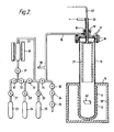
- Figure 2 shows a schematic representation of an illustrative process apparatus
- Figure 3 shows micrographs of brazed-repairs made to superalloy components following a cleaning treatment in accordance with the invention.
- the apparatus shown in Figure 2 comprises a reaction vessel in the form of a 15 litre retort 10 made of Nimonic (trade designation) superalloy material. This material is chosen because of its resistance to halide attack at process temperatures and because its nickel base is compatible with the nickel and cobalt base superalloy materials to be cleaned should any metal transfer occur. Iron based material such as stainless steel should not be used as vessel material for nickel or cobalt based superalloy cleaning applications because transferred metal would cause undesirable surface contamination of the superalloy.
- alumina tube 11 At the lower end of the retort 10, it is enclosed within an alumina tube 11 around which is located a heating element 12.
- the alumina tube 11 and heating element 12 are contained within a thermally insulated furnace box 13 having a nickel foil heat shield 14 on its upper surface.
- the retort 10 is connected to auxiliary gas supply equipment of a pipe 15.
- the pipe 15 is connected to the retort 10 by an end plate and flange assembly 16 which includes '0' ring seals 17.
- On top of the end plate is a screw cap 18 having an '0' ring seal 19.
- Passing through and sealed to the cap 18 is a tube 20 which at its lower end within the retort 10 is connected to a hollow cylindrical condensing member 21.
- a further tube 22 is concentric with the tube 20. Tubes 20 and 22 carry cooling water to cool the condensing member 21.
- the condensing member 21 serves to condense out of the reactive atmosphere within the retort 10, those metal fluorides resulting from the action of the cleaning gas upon the component to be cleaned. This avoids condensation which might otherwise occur within other parts of the apparatus.
- the condensing member 21 also serves to cool the upper part of the retort 10.
- the auxiliary gas supply equipment shown is of an experimental form enabling the supply of various alternative reaction atmospheres for comparative studies.
- the equipment shown incorporates cylinders 23, 24 and 25 containing respectively: argon-lOX fluoroform, hydrogen, and argon.
- Various valves are shown at 27 through 36. Valves 27, 28 and 29 are used for flow rate control for cylinders 23, 24 and 25 respectively. Valves 30 through 33 are used for isolation purposes to enable the selection of alternative gases or mixtures of gases. Valves 34 and 35 are power operated time control valves. Another isolation valve 36 leads to a vacuum pump 26- use of which will be explained later.
- the apparatus also includes a reaction vessel 37 located within a furnace 38.
- This vessel 37 is provided to enable use of reactants based on fluorocarbon polymer powder decomposition products.
- the polymer powder is located within the vesel 37 which is heated by the furnace 38 to a suitable temperature and hydrogen gas may be directed over the powder from the supply in cylinder 24.
- Valve 31 enables the reaction vessel limb of the auxiliary equipment to be isolated.
- a pipe 39 branches from the pipe 15 and leads to a pressure gauge (not shown) used for measurement of the gas pressure in the retort i0.
- the apparatus shown in Figure 2 is operated in the manner of the invention as explained below.
- An article to be cleaned (represented at 40) is placed within the retort 10 upon a suitable support (not shown).
- the retort 10 is then sealed by securing the flange 16 and compressing the seals 17.
- After sealing the retort 10 is evacuated by means of the vacuum pump 26 and back filled with argon drawn from cylinder 25.
- the interior may be heated to the desired reaction temperature, by means of the heating element 12 without causing oxidation of the component 40.
- a selected reactive atmosphere is then introduced into the retort 10 through the power-operated valve 34 for a predetermined time.
- the introduced atmosphere is held in the retort 10 by closing valve 34, then withdrawn by opening valve 35 and operating the vacuum pump 26.
- This cycle of filling, holding, evacuation, holding and refilling is repeated to a predetermined pattern by automatic operation of valves 34 and 35 together with vacuum pump 26 for the duration of the cleaning process.
- the process conditions are predetermined by metering the gas flow rates to determine admixture ratios and by measuring the chamber pressures consequent upon predetermined cycle times and flow rates. In use the process conditions are held to sufficient degree of accuracy by timed operation of valves 34 and 35 and the vacuum pump 26.
- the retort is evacuated of the reactive atmosphere and back-filled with argon before removal of the cleaned component 40.
- a test piece of a superalloy having the trade designation AP1 (composition in weight per cent: 0.03 C; 15.0 Cr; 3.5 Ti; 4.0 A1; 17.0 Co; 5.0 Mo; 0.04 Zr; 0.025 B balance Ni) was mechanically fatigued under controlled conditions to produce a crack therein.
- the crack dimensions were ascertained to the degree of accuracy possible by external scanning electron microscopy. The dimensions were ascertained to be as follows: 1620 ⁇ m deep, 18 ⁇ m across at surface, 10 pm across at 800 ⁇ m depth narrowing to a sharp point at full depth.
- the specimen thus cracked and measured was then articially oxidised to produce a degredation representative of service degradation to approximately 20 ⁇ m depth on the external surfaces.
- the article was then peened to remove as much of the surface oxide as possible by mechanical action leaving an unaffected layer 2-3 ⁇ m thick within the crack.
- the test article was then placed in the reaction vessel which was evacuated and back-filled with argon before heating to the process temperature which was 950°C.
- Hydrogen was drawn from cylinder 24 and passed through the reactor 37 containing an excess of polytetrafluorethylene (PTFE) powder and heated to a temperature of 450°C. Gases drawn from the reactor, comprising hydrogen and the reduction products of PTFE provided the reactive atmosphere used in this experiement.
- PTFE polytetrafluorethylene
- the pressure cycle had the following parameters: cycle duration -40s; filling phase -2s; upper pressure pause 18s; evacuation phase -5s; lower pressure pause -15s; upper pressure 50 torr; lower pressure 5 torr.
- the treatment time was 5h and on completion of the treatment the reaction vessel was evacuated, back-filled with argon and cooled to enable removal of the test article.
- the article which was bright and shiny at the surface was subsequently sectioned through the crack and analysed for oxide along the crack surface using electron microprobe analysis. The surface was found to be substantially free of continuous oxide contamination to the root of the crack and consequently the component is in a very satisfactory state for a braze repair.
- Test pieces of APi superalloy were fatigue and oxidised using the procedure described in Example 1.
- Fùfther test pieces of another commercially superalloy C1023 (which has the composition by weight of: 0.16C; 15.5 Cr; 3.6 Ti; 4.2 Al; 10.0 Co; 8.5 Mo; 0.006B balance NI) were subjected to surface welding to cause the material to crack controllably - the material being one which is unsuitable for welding. These weld cracked test pieces were then oxidised in like manner to the AP1 test pieces.
- Other C1023 articles comprised engine-run nozzle guide vanes.
- Pressure cycle duration -40s; filling phase -2s; upper pressure pause -18s; evacuation phase - 5s; lower pressure pause - 15s.
- a test piece of AP1 alloy was fatigue-cracked, oxidised and peened as described in Example 1. It was then cleaned using the Regime A conditions described in Example 2. The cleaned test piece was then removed to a vacuum brazing chamber in which it was vacuum cleaned to remove any residual trace of the cleaning reactant gases by heating to 1190°C under a vacuum of better than 10- 4 torr and kept thus for lh. The test piece was then brazed using a conventional vacuum brazing technique by placing a foil of braze material around the test piece and heating both under vacuum. The braze material had the following composition in weight per cent: 19 Cr; 10 Si; 0.1 C max; balance Ni.
- FIG. 3 shows optical micrographs of this repaired AP1 specifment at x 60 and x 120 magnifications. It will be seen that the braze repair has penetrated to the root of the crack, that the braze has wetted the substrate surface and fused therewith, and that the interface is free of oxide contamination.
- the segregated structure of the surface braze layer is the normal structure of the eutectic braze material.
- the crack length measured from the x 60 view is some 1300 ⁇ m.
- the invention has been illustrated by reference to examples concerning its principal application that of cleaning superalloy components for repair purposes. However the invention is not limited to such an application.
- the quality control aspect of the invention is extremely important. Moreover it is considered that the invention could be utilised in the Tepair of heat resistant steels and the repair of flaws in expensive castings.
Landscapes
- Chemical & Material Sciences (AREA)
- Chemical Kinetics & Catalysis (AREA)
- General Chemical & Material Sciences (AREA)
- Engineering & Computer Science (AREA)
- Materials Engineering (AREA)
- Mechanical Engineering (AREA)
- Metallurgy (AREA)
- Organic Chemistry (AREA)
- Cleaning And De-Greasing Of Metallic Materials By Chemical Methods (AREA)
- Cleaning In General (AREA)
- ing And Chemical Polishing (AREA)
Applications Claiming Priority (3)
| Application Number | Priority Date | Filing Date | Title |
|---|---|---|---|
| GB858517766A GB8517766D0 (en) | 1985-07-15 | 1985-07-15 | Cleaning of metallic components |
| GB8517766 | 1985-07-15 | ||
| CA000513950A CA1295215C (en) | 1985-07-15 | 1986-07-16 | Cleaning of metal articles |
Publications (2)
| Publication Number | Publication Date |
|---|---|
| EP0209307A1 true EP0209307A1 (de) | 1987-01-21 |
| EP0209307B1 EP0209307B1 (de) | 1988-09-07 |
Family
ID=25671049
Family Applications (1)
| Application Number | Title | Priority Date | Filing Date |
|---|---|---|---|
| EP86305244A Expired EP0209307B1 (de) | 1985-07-15 | 1986-07-07 | Reinigung von Metallgegenständen |
Country Status (4)
| Country | Link |
|---|---|
| US (1) | US4698130A (de) |
| EP (1) | EP0209307B1 (de) |
| JP (1) | JPH0791662B2 (de) |
| CA (1) | CA1295215C (de) |
Cited By (20)
| Publication number | Priority date | Publication date | Assignee | Title |
|---|---|---|---|---|
| EP0493122A3 (en) * | 1990-12-27 | 1993-04-14 | Ogihara Technical Center Co Ltd | Method and apparatus for recovering substance adhered to object to be processed |
| WO1993017149A1 (en) * | 1992-02-25 | 1993-09-02 | Baxter International Inc. | Method and apparatus for cleaning with a volatile solvent |
| EP0814179A1 (de) * | 1996-06-17 | 1997-12-29 | General Electric Company | Verfahren zum Entfernen einer Diffusionsbeschichtung von einer Legierung auf Nickelbasis |
| US5735933A (en) * | 1994-07-29 | 1998-04-07 | Teruhisa Ogihara | Method for processing metallic waste |
| WO2006061338A1 (de) | 2004-12-10 | 2006-06-15 | Siemens Aktiengesellschaft | Verfahren zum reinigen eines werkstückes mit halogenionen |
| WO2007003615A1 (de) * | 2005-07-06 | 2007-01-11 | Siemens Aktiengesellschaft | Verfahren zum reinigen von oberflächen mit fluoridionen |
| WO2009106044A1 (de) * | 2008-02-28 | 2009-09-03 | Mtu Aero Engines Gmbh | Verfahren zum thermochemischen reinigen und/oder strippen von turbinenbauteilen |
| EP2762612A1 (de) * | 2013-02-01 | 2014-08-06 | Siemens Aktiengesellschaft | FIC-Reinigung im Unterdruck |
| US9353625B2 (en) | 2009-01-13 | 2016-05-31 | General Electric Technology Gmbh | Device for cleaning oxidized or corroded components in the presence of a halogenous gas mixture |
| WO2019057555A1 (en) * | 2017-09-19 | 2019-03-28 | Bortec Gmbh & Co. Kg | METHOD FOR ENHANCED PRETREATMENT OF A SURFACE OF A METALLIC SUBSTRATE |
| FR3088346A1 (fr) * | 2018-11-14 | 2020-05-15 | Safran Aircraft Engines | Procede de decapage d’une piece de turbomachine |
| WO2022040146A1 (en) * | 2020-08-18 | 2022-02-24 | Applied Materials, Inc. | Methods for cleaning aerospace components |
| US11384648B2 (en) | 2018-03-19 | 2022-07-12 | Applied Materials, Inc. | Methods for depositing coatings on aerospace components |
| US11466364B2 (en) | 2019-09-06 | 2022-10-11 | Applied Materials, Inc. | Methods for forming protective coatings containing crystallized aluminum oxide |
| US11519066B2 (en) | 2020-05-21 | 2022-12-06 | Applied Materials, Inc. | Nitride protective coatings on aerospace components and methods for making the same |
| US11697879B2 (en) | 2019-06-14 | 2023-07-11 | Applied Materials, Inc. | Methods for depositing sacrificial coatings on aerospace components |
| US11732353B2 (en) | 2019-04-26 | 2023-08-22 | Applied Materials, Inc. | Methods of protecting aerospace components against corrosion and oxidation |
| US11739429B2 (en) | 2020-07-03 | 2023-08-29 | Applied Materials, Inc. | Methods for refurbishing aerospace components |
| US11753726B2 (en) | 2018-04-27 | 2023-09-12 | Applied Materials, Inc. | Protection of components from corrosion |
| US11794382B2 (en) | 2019-05-16 | 2023-10-24 | Applied Materials, Inc. | Methods for depositing anti-coking protective coatings on aerospace components |
Families Citing this family (26)
| Publication number | Priority date | Publication date | Assignee | Title |
|---|---|---|---|---|
| US4836860A (en) * | 1987-04-06 | 1989-06-06 | Trw Inc. | Method for cleaning spacecraft critical surfaces |
| US4898347A (en) * | 1987-04-06 | 1990-02-06 | Trw Inc. | Method for cleaning spacecraft critical surfaces |
| US4997520A (en) * | 1988-06-10 | 1991-03-05 | Texas Instruments Incorporated | Method for etching tungsten |
| GB8827933D0 (en) * | 1988-11-30 | 1989-01-05 | Plessey Co Plc | Improvements relating to soldering processes |
| US5367139A (en) * | 1989-10-23 | 1994-11-22 | International Business Machines Corporation | Methods and apparatus for contamination control in plasma processing |
| US5415193A (en) * | 1992-11-13 | 1995-05-16 | Taricco; Todd | Pressure controlled cleaning system |
| US5460689A (en) * | 1994-02-28 | 1995-10-24 | Applied Materials, Inc. | High pressure plasma treatment method and apparatus |
| DE19601436A1 (de) * | 1996-01-17 | 1997-07-24 | Siegfried Dr Ing Straemke | Verfahren und Vorrichtung zur Oberflächenbehandlung von Werkstücken |
| US5898994A (en) * | 1996-06-17 | 1999-05-04 | General Electric Company | Method for repairing a nickel base superalloy article |
| US6416589B1 (en) * | 1999-02-18 | 2002-07-09 | General Electric Company | Carbon-enhanced fluoride ion cleaning |
| US6328810B1 (en) | 1999-04-07 | 2001-12-11 | General Electric Company | Method for locally removing oxidation and corrosion product from the surface of turbine engine components |
| US6537816B1 (en) * | 1999-06-14 | 2003-03-25 | General Electric Company | Standards, methods for making, and methods for using the standards in evaluation of oxide removal |
| US6712080B1 (en) * | 2002-02-15 | 2004-03-30 | The United States Of America As Represented By The Secretary Of The Army | Flushing system for removing lubricant coking in gas turbine bearings |
| EP1497059B1 (de) * | 2002-04-11 | 2008-07-23 | Rolls-Royce Corporation | Verfahren und vorrichtung zum entfernen von keramikmaterial von gusskomponenten |
| US20050035085A1 (en) * | 2003-08-13 | 2005-02-17 | Stowell William Randolph | Apparatus and method for reducing metal oxides on superalloy articles |
| DE102005051310A1 (de) * | 2005-10-26 | 2007-05-03 | Siemens Ag | Reinigung von oxidierten oder korrodierten Bauteilen |
| WO2007048698A1 (de) * | 2005-10-26 | 2007-05-03 | Siemens Aktiengesellschaft | Technologie zur reinigung von thermoermüdungsrissen in nbs mit hohem anteil von chrom |
| US20080245845A1 (en) * | 2007-04-04 | 2008-10-09 | Lawrence Bernard Kool | Brazing formulation and method of making the same |
| CN101821430B (zh) * | 2007-10-10 | 2012-10-10 | 西门子公司 | 用于对构件进行氟离子清洗的方法 |
| JP2009285664A (ja) * | 2008-05-27 | 2009-12-10 | Toshiba Corp | ロウ付け補修材料およびその材料を使用したロウ付け補修方法 |
| US20100108107A1 (en) * | 2008-10-31 | 2010-05-06 | General Electric Company | System and apparatus for fluoride ion cleaning |
| EP2192209B1 (de) | 2008-11-17 | 2016-04-06 | Alstom Technology Ltd | Vorrichtung zur Reinigung oxidierter oder korrodierter Bauteile in Gegenwart eines halogenhaltigen Gasgemisches |
| US9205509B2 (en) * | 2011-08-31 | 2015-12-08 | General Electric Company | Localized cleaning process and apparatus therefor |
| CN104169470B (zh) * | 2012-03-28 | 2016-09-28 | 通用电器技术有限公司 | 用于从陶瓷部分分离金属部分的方法 |
| US10279416B2 (en) | 2016-03-15 | 2019-05-07 | General Electric Company | Weld forced crack and braze repair for superalloys |
| CN109023408A (zh) * | 2018-08-21 | 2018-12-18 | 江航 | 高温合金氧化物还原装置 |
Citations (9)
| Publication number | Priority date | Publication date | Assignee | Title |
|---|---|---|---|---|
| DE2002317A1 (de) * | 1969-01-23 | 1970-11-26 | Montedison Spa | Praeparat und Reinigungsverfahren |
| US4098450A (en) * | 1977-03-17 | 1978-07-04 | General Electric Company | Superalloy article cleaning and repair method |
| DE2724943B2 (de) * | 1976-06-04 | 1978-07-13 | Rhone-Poulenc Industries S.A., Paris | Reinigungsmittel, insbesondere für Leichtmetalle |
| US4188237A (en) * | 1978-02-02 | 1980-02-12 | University Of Dayton | Method for cleaning metal parts with elemental fluorine |
| DD154603A1 (de) * | 1980-11-21 | 1982-04-07 | Maetzing Hans Dieter | Verfahren zur selektiven fluorierung von methanchloriden |
| US4324594A (en) * | 1978-02-02 | 1982-04-13 | University Of Dayton | Method for cleaning metal parts |
| US4328044A (en) * | 1978-02-02 | 1982-05-04 | University Of Dayton | Method for cleaning metal parts |
| US4405379A (en) * | 1980-02-06 | 1983-09-20 | University Of Dayton | Method for cleaning metal parts |
| US4500567A (en) * | 1982-12-23 | 1985-02-19 | Nippon Sheet Glass Co., Ltd. | Method for forming tin oxide coating |
Family Cites Families (4)
| Publication number | Priority date | Publication date | Assignee | Title |
|---|---|---|---|---|
| US3205105A (en) * | 1963-03-11 | 1965-09-07 | Ford Motor Co | Casting cleaning |
| US4159917A (en) * | 1977-05-27 | 1979-07-03 | Eastman Kodak Company | Method for use in the manufacture of semiconductor devices |
| DE3309448C2 (de) * | 1983-03-16 | 1985-06-05 | MTU Motoren- und Turbinen-Union München GmbH, 8000 München | Verfahren zum Erkennen von Gefügeinhomogenitäten in Titanlegierungsproben und Schweißlingen |
| US4605479A (en) * | 1985-06-24 | 1986-08-12 | Rca Corporation | In-situ cleaned ohmic contacts |
-
1986
- 1986-07-07 EP EP86305244A patent/EP0209307B1/de not_active Expired
- 1986-07-15 JP JP61166567A patent/JPH0791662B2/ja not_active Expired - Fee Related
- 1986-07-16 CA CA000513950A patent/CA1295215C/en not_active Expired - Lifetime
- 1986-08-29 US US06/885,442 patent/US4698130A/en not_active Expired - Lifetime
Patent Citations (9)
| Publication number | Priority date | Publication date | Assignee | Title |
|---|---|---|---|---|
| DE2002317A1 (de) * | 1969-01-23 | 1970-11-26 | Montedison Spa | Praeparat und Reinigungsverfahren |
| DE2724943B2 (de) * | 1976-06-04 | 1978-07-13 | Rhone-Poulenc Industries S.A., Paris | Reinigungsmittel, insbesondere für Leichtmetalle |
| US4098450A (en) * | 1977-03-17 | 1978-07-04 | General Electric Company | Superalloy article cleaning and repair method |
| US4188237A (en) * | 1978-02-02 | 1980-02-12 | University Of Dayton | Method for cleaning metal parts with elemental fluorine |
| US4324594A (en) * | 1978-02-02 | 1982-04-13 | University Of Dayton | Method for cleaning metal parts |
| US4328044A (en) * | 1978-02-02 | 1982-05-04 | University Of Dayton | Method for cleaning metal parts |
| US4405379A (en) * | 1980-02-06 | 1983-09-20 | University Of Dayton | Method for cleaning metal parts |
| DD154603A1 (de) * | 1980-11-21 | 1982-04-07 | Maetzing Hans Dieter | Verfahren zur selektiven fluorierung von methanchloriden |
| US4500567A (en) * | 1982-12-23 | 1985-02-19 | Nippon Sheet Glass Co., Ltd. | Method for forming tin oxide coating |
Non-Patent Citations (2)
| Title |
|---|
| PATENT ABSTRACTS OF JAPAN, unexamined applications, C field, vol. 5, no. 41, March 18, 1981 THE PATENT OFFICE JAPANESE GOVERNMENT page 74 C 47 * JP - A - 55-164 077 ( CHO LSI GIJUTSU KENKYU KUMIAI ) * * |
| PATENT ABSTRACTS OF JAPAN, unexamined applications, C field, vol. 9, no. 254, October 11, 1985 THE PATENT OFFICE JAPANESE GOVERNMENT page 71 C 308 * JP - A - 60-106 984 ( MITSUI FLUORO CHEMICAL K.K. ) ( 12-06-1985 ) * * |
Cited By (30)
| Publication number | Priority date | Publication date | Assignee | Title |
|---|---|---|---|---|
| US5304253A (en) * | 1990-09-12 | 1994-04-19 | Baxter International Inc. | Method for cleaning with a volatile solvent |
| EP0493122A3 (en) * | 1990-12-27 | 1993-04-14 | Ogihara Technical Center Co Ltd | Method and apparatus for recovering substance adhered to object to be processed |
| WO1993017149A1 (en) * | 1992-02-25 | 1993-09-02 | Baxter International Inc. | Method and apparatus for cleaning with a volatile solvent |
| US5735933A (en) * | 1994-07-29 | 1998-04-07 | Teruhisa Ogihara | Method for processing metallic waste |
| EP0814179A1 (de) * | 1996-06-17 | 1997-12-29 | General Electric Company | Verfahren zum Entfernen einer Diffusionsbeschichtung von einer Legierung auf Nickelbasis |
| WO2006061338A1 (de) | 2004-12-10 | 2006-06-15 | Siemens Aktiengesellschaft | Verfahren zum reinigen eines werkstückes mit halogenionen |
| WO2007003615A1 (de) * | 2005-07-06 | 2007-01-11 | Siemens Aktiengesellschaft | Verfahren zum reinigen von oberflächen mit fluoridionen |
| DE102005032685B4 (de) * | 2005-07-06 | 2007-06-14 | Siemens Ag | Verfahren zum Reinigen von Oberflächen mit Halogenionen und Reinigungsanlage |
| WO2009106044A1 (de) * | 2008-02-28 | 2009-09-03 | Mtu Aero Engines Gmbh | Verfahren zum thermochemischen reinigen und/oder strippen von turbinenbauteilen |
| US9353625B2 (en) | 2009-01-13 | 2016-05-31 | General Electric Technology Gmbh | Device for cleaning oxidized or corroded components in the presence of a halogenous gas mixture |
| EP2762612A1 (de) * | 2013-02-01 | 2014-08-06 | Siemens Aktiengesellschaft | FIC-Reinigung im Unterdruck |
| WO2019057555A1 (en) * | 2017-09-19 | 2019-03-28 | Bortec Gmbh & Co. Kg | METHOD FOR ENHANCED PRETREATMENT OF A SURFACE OF A METALLIC SUBSTRATE |
| US11492693B2 (en) | 2017-09-19 | 2022-11-08 | Bortec Gmbh | Pre-treatment process of a surface of a metallic substrate |
| US11603767B2 (en) | 2018-03-19 | 2023-03-14 | Applied Materials, Inc. | Methods of protecting metallic components against corrosion using chromium-containing thin films |
| US11560804B2 (en) | 2018-03-19 | 2023-01-24 | Applied Materials, Inc. | Methods for depositing coatings on aerospace components |
| US11384648B2 (en) | 2018-03-19 | 2022-07-12 | Applied Materials, Inc. | Methods for depositing coatings on aerospace components |
| US11761094B2 (en) | 2018-04-27 | 2023-09-19 | Applied Materials, Inc. | Protection of components from corrosion |
| US11753727B2 (en) | 2018-04-27 | 2023-09-12 | Applied Materials, Inc. | Protection of components from corrosion |
| US11753726B2 (en) | 2018-04-27 | 2023-09-12 | Applied Materials, Inc. | Protection of components from corrosion |
| WO2020099794A1 (fr) * | 2018-11-14 | 2020-05-22 | Safran Aircraft Engines | Procédé de décapage d'une pièce de turbomachine |
| FR3088346A1 (fr) * | 2018-11-14 | 2020-05-15 | Safran Aircraft Engines | Procede de decapage d’une piece de turbomachine |
| CN113015822A (zh) * | 2018-11-14 | 2021-06-22 | 赛峰飞机发动机公司 | 对涡轮机部件进行酸洗的方法 |
| US11732353B2 (en) | 2019-04-26 | 2023-08-22 | Applied Materials, Inc. | Methods of protecting aerospace components against corrosion and oxidation |
| US11794382B2 (en) | 2019-05-16 | 2023-10-24 | Applied Materials, Inc. | Methods for depositing anti-coking protective coatings on aerospace components |
| US11697879B2 (en) | 2019-06-14 | 2023-07-11 | Applied Materials, Inc. | Methods for depositing sacrificial coatings on aerospace components |
| US11466364B2 (en) | 2019-09-06 | 2022-10-11 | Applied Materials, Inc. | Methods for forming protective coatings containing crystallized aluminum oxide |
| US11519066B2 (en) | 2020-05-21 | 2022-12-06 | Applied Materials, Inc. | Nitride protective coatings on aerospace components and methods for making the same |
| US11739429B2 (en) | 2020-07-03 | 2023-08-29 | Applied Materials, Inc. | Methods for refurbishing aerospace components |
| WO2022040146A1 (en) * | 2020-08-18 | 2022-02-24 | Applied Materials, Inc. | Methods for cleaning aerospace components |
| EP4200089A4 (de) * | 2020-08-18 | 2024-10-16 | Applied Materials, Inc. | Verfahren zur reinigung von luft- und raumfahrtkomponenten |
Also Published As
| Publication number | Publication date |
|---|---|
| EP0209307B1 (de) | 1988-09-07 |
| JPS6277484A (ja) | 1987-04-09 |
| JPH0791662B2 (ja) | 1995-10-04 |
| US4698130A (en) | 1987-10-06 |
| CA1295215C (en) | 1992-02-04 |
Similar Documents
| Publication | Publication Date | Title |
|---|---|---|
| EP0209307B1 (de) | Reinigung von Metallgegenständen | |
| Lee et al. | Effects of sulfur impurity on the scale adhesion behavior of a desulfurized Ni-based superalloy aluminized by chemical vapor deposition | |
| US4317685A (en) | Method for removing a scale from a superalloy surface | |
| EP1107867B1 (de) | Entfernung einer thermischen isolierbeschichtung | |
| US4889589A (en) | Gaseous removal of ceramic coatings | |
| GB1591436A (en) | Superalloy article cleaning and repair methods | |
| US11192792B2 (en) | Boronizing powder compositions for improved boride layer quality in oil country tubular goods and other metal articles | |
| KR20000048100A (ko) | 부식 방법 | |
| US20110120972A1 (en) | Replacement process for fluoride ion cleaning | |
| EP1795629A2 (de) | Rostreinigung und Beschichtung metallischer Bestandteile | |
| Ning et al. | High-performance processing for film cooling holes on EB-PVD TBC-coated superalloys utilizing assisted electrode electrochemical discharge machining | |
| EP0237153B1 (de) | Verfahren zum Entfernen von Schutz- und Verbindungsschichten von Metallgegenständen | |
| EP3431186B1 (de) | Kaltspritzdüse | |
| NO812605L (no) | Fremgangsmaate ved paafoering av et belegg paa et substrat | |
| CA2998048A1 (en) | Boronizing powder compositions for improved boride layer quality in oil country tubular goods and other metal articles | |
| Fomina et al. | Methods of cleaning the surface of the blades of gas turbine engines from carbon deposits and oxidation products | |
| Cocke et al. | Preparation by intermetallic compound oxidation of supported nickel on titania overlayers | |
| Dayal | Laser surface modification for improving localised corrosion resistance of austenitic stainless steels | |
| Di Gabriele et al. | Study of the metal dusting behaviour of high‐temperature alloys | |
| Burman et al. | Coatings with lenticular oxides preventing interdiffusion | |
| JPS59166681A (ja) | 耐食部材 | |
| Azarbayjani et al. | System development for evaluating performance of corrosion resistant coatings exposed to molten copper chloride salt | |
| Whittenberger | Tensile properties and structure of several superalloys after long-term exposure to LiF and vacuum at 1173 K | |
| CN1212028A (zh) | 钛和钛合金的等离子体除锈皮 | |
| Ioka et al. | EVALUATION OF CONTAINER USING HYBRID TECHNIQUE FOR THERMOCHEMICAL WATER-SPLITTING IODINE-SULFUR PROCESS |
Legal Events
| Date | Code | Title | Description |
|---|---|---|---|
| PUAI | Public reference made under article 153(3) epc to a published international application that has entered the european phase |
Free format text: ORIGINAL CODE: 0009012 |
|
| AK | Designated contracting states |
Kind code of ref document: A1 Designated state(s): CH DE FR GB IT LI SE |
|
| 17P | Request for examination filed |
Effective date: 19870223 |
|
| 17Q | First examination report despatched |
Effective date: 19880128 |
|
| ITF | It: translation for a ep patent filed | ||
| GRAA | (expected) grant |
Free format text: ORIGINAL CODE: 0009210 |
|
| AK | Designated contracting states |
Kind code of ref document: B1 Designated state(s): CH DE FR GB IT LI SE |
|
| REF | Corresponds to: |
Ref document number: 3660682 Country of ref document: DE Date of ref document: 19881013 |
|
| ET | Fr: translation filed | ||
| PLBE | No opposition filed within time limit |
Free format text: ORIGINAL CODE: 0009261 |
|
| STAA | Information on the status of an ep patent application or granted ep patent |
Free format text: STATUS: NO OPPOSITION FILED WITHIN TIME LIMIT |
|
| 26N | No opposition filed | ||
| ITTA | It: last paid annual fee | ||
| EAL | Se: european patent in force in sweden |
Ref document number: 86305244.5 |
|
| REG | Reference to a national code |
Ref country code: GB Ref legal event code: IF02 |
|
| PGFP | Annual fee paid to national office [announced via postgrant information from national office to epo] |
Ref country code: FR Payment date: 20020610 Year of fee payment: 17 |
|
| PGFP | Annual fee paid to national office [announced via postgrant information from national office to epo] |
Ref country code: GB Payment date: 20020612 Year of fee payment: 17 |
|
| PGFP | Annual fee paid to national office [announced via postgrant information from national office to epo] |
Ref country code: SE Payment date: 20020617 Year of fee payment: 17 Ref country code: CH Payment date: 20020617 Year of fee payment: 17 |
|
| PGFP | Annual fee paid to national office [announced via postgrant information from national office to epo] |
Ref country code: DE Payment date: 20020619 Year of fee payment: 17 |
|
| REG | Reference to a national code |
Ref country code: FR Ref legal event code: TP |
|
| REG | Reference to a national code |
Ref country code: GB Ref legal event code: 732E |
|
| REG | Reference to a national code |
Ref country code: CH Ref legal event code: PUE Owner name: QINETIQ LIMITED Free format text: THE SECRETARY OF STATE FOR DEFENCE IN HER BRITANNIC MAJESTY'S GOVERNMENT OF THE#UNITED KINGDOM .. WHITEHALL#LONDON SW1A 2HB (GB) -TRANSFER TO- QINETIQ LIMITED#85 BUCKINGHAM GATE#LONDON, SW1 6TD (GB) |
|
| PG25 | Lapsed in a contracting state [announced via postgrant information from national office to epo] |
Ref country code: GB Free format text: LAPSE BECAUSE OF NON-PAYMENT OF DUE FEES Effective date: 20030707 |
|
| PG25 | Lapsed in a contracting state [announced via postgrant information from national office to epo] |
Ref country code: SE Free format text: LAPSE BECAUSE OF NON-PAYMENT OF DUE FEES Effective date: 20030708 |
|
| PG25 | Lapsed in a contracting state [announced via postgrant information from national office to epo] |
Ref country code: LI Free format text: LAPSE BECAUSE OF NON-PAYMENT OF DUE FEES Effective date: 20030731 Ref country code: CH Free format text: LAPSE BECAUSE OF NON-PAYMENT OF DUE FEES Effective date: 20030731 |
|
| PG25 | Lapsed in a contracting state [announced via postgrant information from national office to epo] |
Ref country code: DE Free format text: LAPSE BECAUSE OF NON-PAYMENT OF DUE FEES Effective date: 20040203 |
|
| GBPC | Gb: european patent ceased through non-payment of renewal fee |
Effective date: 20030707 |
|
| EUG | Se: european patent has lapsed | ||
| REG | Reference to a national code |
Ref country code: CH Ref legal event code: PL |
|
| PG25 | Lapsed in a contracting state [announced via postgrant information from national office to epo] |
Ref country code: FR Free format text: LAPSE BECAUSE OF NON-PAYMENT OF DUE FEES Effective date: 20040331 |
|
| REG | Reference to a national code |
Ref country code: FR Ref legal event code: ST |
|
| PG25 | Lapsed in a contracting state [announced via postgrant information from national office to epo] |
Ref country code: IT Free format text: LAPSE BECAUSE OF NON-PAYMENT OF DUE FEES;WARNING: LAPSES OF ITALIAN PATENTS WITH EFFECTIVE DATE BEFORE 2007 MAY HAVE OCCURRED AT ANY TIME BEFORE 2007. THE CORRECT EFFECTIVE DATE MAY BE DIFFERENT FROM THE ONE RECORDED. Effective date: 20050707 |