EP0209310A2 - Dispositif de compensation axiale pour un moteur de forage de fond de puits - Google Patents
Dispositif de compensation axiale pour un moteur de forage de fond de puits Download PDFInfo
- Publication number
- EP0209310A2 EP0209310A2 EP86305258A EP86305258A EP0209310A2 EP 0209310 A2 EP0209310 A2 EP 0209310A2 EP 86305258 A EP86305258 A EP 86305258A EP 86305258 A EP86305258 A EP 86305258A EP 0209310 A2 EP0209310 A2 EP 0209310A2
- Authority
- EP
- European Patent Office
- Prior art keywords
- shaft
- downhole drilling
- drilling motor
- fluid
- thrust bearing
- Prior art date
- Legal status (The legal status is an assumption and is not a legal conclusion. Google has not performed a legal analysis and makes no representation as to the accuracy of the status listed.)
- Withdrawn
Links
Images




Classifications
-
- F—MECHANICAL ENGINEERING; LIGHTING; HEATING; WEAPONS; BLASTING
- F03—MACHINES OR ENGINES FOR LIQUIDS; WIND, SPRING, OR WEIGHT MOTORS; PRODUCING MECHANICAL POWER OR A REACTIVE PROPULSIVE THRUST, NOT OTHERWISE PROVIDED FOR
- F03B—MACHINES OR ENGINES FOR LIQUIDS
- F03B13/00—Adaptations of machines or engines for special use; Combinations of machines or engines with driving or driven apparatus; Power stations or aggregates
- F03B13/02—Adaptations for drilling wells
-
- E—FIXED CONSTRUCTIONS
- E21—EARTH OR ROCK DRILLING; MINING
- E21B—EARTH OR ROCK DRILLING; OBTAINING OIL, GAS, WATER, SOLUBLE OR MELTABLE MATERIALS OR A SLURRY OF MINERALS FROM WELLS
- E21B4/00—Drives for drilling, used in the borehole
- E21B4/02—Fluid rotary type drives
Definitions
- This invention relates to an axial balancing device for downhole drilling motors, in particular turbodrills.
- a turbodrill is a downhole drilling tool for drilling of oil wells or the like and essentially consists of an outer casing within which is mounted a rotatable shaft carrying at its lower end a drill bit for drilling of the well.
- Drilling mud is arranged to be fed at pressure into the area between the casing and the shaft, the drilling mud passing down the drilling motor through suitable passageways to the drill bit where it serves to lubricate and clean the drill bit before being fed upwardly between the outside of the casing and the well bore to the surface where it can be cleaned and recycled.
- the shaft is rotatably driven within the casing by a turbine section consisting of a plurality of annular turbine stages.
- Each turbine unit comprises a stator and a rotor having a plurality of blades or vanes of curved profile disposed annularly about the axis of rotation of the shaft.
- the stator normally is fixedly located in the bore of the casing and the rotor is fixedly attached to the rotatable shaft.
- the mud interacts with the co-operating blades of the stator and rotor of each turbine unit in order to cause rotation of the shaft relative to the casing and apply a torque to the drill bit connected thereto.
- PCD polycrystalline diamond
- PCD bits have found application with rotary drilling and with positive displacement downhole mud motors.
- drilling speeds are very low, typically less than 100 RPM and furthermore for deep and deviated wells a significant proportion of the power put into the drill string at the surface is lost in friction resulting in a comparatively low net torque at the bit.
- Mud motors particularly in the larger sizes, are also restricted to comparatively low rotational speeds and limitations on supply pressure and torque, and also suffer from higher wear rates than turbodrills and therefore have their own limitations despite being better matched to the requirements of PCD bits.
- An object of the present invention is to provide an axial thrust arrangement for a turbodrill and which will assist the turbodrill in efficient operation when used with bits having the drilling characteristics of PCD bits.
- a downhole drilling motor comprising an outer drill ⁇ casing, a shaft for driving a drill bit connected thereto and said shaft being rotatable relative to said casing, turbine means extending between said casing and shaft for enabling rotation of said shaft, an inlet for admitting fluid under pressure, and passage means interconnecting said inlet and turbine means whereby pressurised fluid can be transmitted to the turbine means to effect operation thereof, characterised in that the shaft is provided with reaction means accessible to the pressure fluid in said passage means, said reaction means having surfaces which can be acted upon by the pressure fluid to produce a force acting counter to the normal hydraulic thrust on the shaft thereby producing a reduced resultant hydraulic thrust on the shaft.
- the reaction means comprises sleeve means fixedly mounted on the shaft, said sleeve and shaft having pressure surfaces which can be acted upon by unequal pressures from the pressure fluid to induce a force on the shaft counter to the normal direction of flow of the pressure fluid along the drill.
- the reaction means is located in the drilling tool above the turbine means.
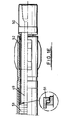
- a downhole drilling tool or turbodrill comprises a connector 10 for connecting the drill tool to a supply of drilling fluid or mud under pressure.
- the connector 10 is fitted to a casing 11 of a drill string which is substantially non- rotatable within a well bore or may be rotated at low speed.
- Carried within the casing 11 is a rotatable shaft 12, the outer diameter of which is radially spaced from the internal diameter of the casing 11.
- the connector 10 has a central passage 13 through which drilling mud under pressure can be supplied to a turbine section 14 for driving the shaft 12, the turbine section 14 (Fig. 1B) comprising a plurality of co-operating turbine units 15.
- a transverse face 16 of a cover 17 which seals, by means of O-rings 18, against the inside surface of the casing 11.
- the cover 17 has extending therefrom, in an axial direction, an integral cylindrical wall or skirt 19 which defines an annular pressure chamber 20 between the outer circumference of the wall 19 and the inner circumference of the casing 11. Ports 21 in the cover 17 interconnect the passage 13 and the chamber 20.
- the lower end of the chamber 20 opens into a turbine pressure supply chamber 22.
- Pressurised fluid at a given pressure passing into the chamber 22 for driving the turbine section 14 automatically causes that pressure to be applied to an axial thrust balancing device having lower end faces 23 and 24 on a cylindrical sleeve 25 and associated fixed bush 26 respectively.
- the sleeve 25 is fixed to the outside of the shaft 12 and is provided on its external surface with a series of circumferential grooves 27.
- the bush 26 closely surrounds the external surface of the sleeve 25 but is spaced therefrom by a small clearance gap 28 sufficient to permit a small supply of pressurised fluid to pass between the sleeve 25 and bush 26 to act on the radial surfaces of the grooves 27 before leaking in controlled manner with a corresponding reduction of pressure into chamber 29 from where the fluid passes freely out of the drilling tool through radial holes 30 without communication with ports 21 to the annulus between the outside of the casing 11 and the wall of the borehole. It will be noted that, at its upper end, the bush 26 abuts against a shoulder formed on the inside of wall 19.
- the drilling tool is broken into upper and lower portions interconnected by a coupling designated generally by the reference numeral 34.
- the coupling 34 comprises an outer sleeve 35 which is provided with screw-threads 35a and 35b whereby the sleeve 35 can be releasably connected to the upper and lower portions of the drill casing 11.
- the coupling 34 also includes male and female screw-threaded junction pieces 36,37 fixed to the lower end of the upper portion of shaft 12 and the upper end of the lower portion of shaft 12 respectively.
- each thrust bearing 41 consists of an annular metal ring 42 formed with a radially-extending web 43 to the upper and lower surfaces of which are moulded, at spaced intervals therearound, a plurality of thrust pads 44 of rubber or similar elastomeric resilient, wear- resistant material.
- Each ring 42 is formed radially outwardly of the pads 44 with the ports 40 which permit pressure fluid to flow longitudinally past the thrust bearings.
- each thrust pad 44 is operatively disposed in frictional engagement between a pair of co-operating thrust collars 45 secured to the shaft 12. Residual axial thrust is accommodated by the axial thrust bearings 41.
- each thrust pad 44 is formed with radial grooves 46 and its surface which engages an adjacent thrust collar 45 is profiled by being tapered upwards towards its circumferential trailing edge.
- the combination of the profiled rubber thrust pads 44 and their grooves 46 result in the formation of a lubricating film which provides the bearings with a substantially lower co-efficient of friction and therefore lower wear rates than bearings of previously proposed types of drilling tool.
- a labyrinth seal 51 of known construction and radial journal bearing 52 which absorbs mechanical vibration forces during operation of the drill bit are provided at the lower end of the tool (Fig. lE).
- pressurised drilling mud at high pressure is supplied into passage 13 and acts on the upper face 16 of cover 17 to tend to urge the drilling tool downwardly.
- the pressurised inlet fluid then flows from passage 13 through ports 19, pressure chamber 20 and turbine pressure supply chamber 22 to the turbine section 14.
- the pressure fluid acts on the lower faces (23,24) of sleeve 25 and bush 26 respectively and a small proportion, say 5%, flows upwardly through clearance gap 28, into chamber 29 and out of the drilling tool through holes 30.
- the pressure of the fluid in chamber 29 is substantially lower than that on faces 23,24 and serves to reduce and tends to balance the downward hydraulic thrust on the drilling tool to a level such that when operating with weight on the bit, the residual load on the axial thrust bearings of the drilling tool is minimal.
- drill tools incorporating such a device operate more efficiently and are subject to lower bearing wear rates than conventional drilling tools.
- the drilling tool as described above is suitable for use with PCD bits which operate at low weights on the bit due to the fact that the downward hydraulic axial thrust on the drill tool is balanced to a significant extent.
- a drilling tool is shown in which the axial thrust bearing, axial thrust balancing device and turbine section are disposed differently relative to each other in the body of the drilling tool as compared with the embodiment of Figs. 1 to 3.
- like parts will be given the same reference numerals as in Figs. 1 to 3.
- a downhole drilling tool comprises a connector 10 for connection to a supply of drilling fluid or mud under pressure, the connector being fitted to casing 11 as in the previous embodiment.
- the central passage 13 of the connector 10 allows pressurised fluid to be fed axially past the outside wall of an axial thrust bearing containment wall or casing 19 located at the top end of the drilling tool above turbine section 14(Fig. 4C).
- a body portion 61 defines a cylinder 62 within which a flexible wall in the form of a piston 63 is slidable.
- the flexible wall may be provided by a bellows.
- the cylindrical wall or skirt 19 extends downwardly in an axial direction substantially as in the embodiment of Figs. lA-lE.
- Ports 64 extend through the body portion 61 to interconnect the passage 13 with annular pressure chamber 20 between the outer circumference of wall 19 and the inner circumference of casing 11.
- the axial thrust bearing comprises a sealed chamber 65 filled or partially filled with a lubricating fluid such as oil and within which is housed a rotating bearing sleeve 66a mounted on a bearing shaft 66, the upper wall of the chamber 65 being defined by the piston 63 which allows for expansion or contraction of the sealed fluid as downhole pressure and temperatures vary. Furthermore, it allows for equalisation of the fluid pressure within the chamber 65 to that of the surrounding drilling mud.
- a plurality of bearings 68 for example ball or roller bearings, dynamically protected from drill bit dynamic loads by means of resilient mountings 68a.
- the upper end of the sealed chamber is closed by the piston 63 having a peripheral sealing ring 69 sealing against the inner surface of cylinder 62.
- the lower end of the bearing chamber 65 is sealed at its lower end by a shaft sealing system which is typically one or more rotary face-type seals 70 in combination with stationary lip-type shaft seals 71.
- the stationary lip seals 71 act as a barrier to prevent abrasive particles contained in drilling mud admitted to chamber 72 gaining access to the face seals 70.
- Drilling mud passing through the gap between rotary sleeve 25 and stationary bush 26 then passes to the annulus around casing 11 of the drill via drilled radial holes 73 without communication with chamber 20.
- Radial holes 74 allow annular pressure from the outside of casing 11 to be fed to the top side of piston 63 without communication with passage 13.
- axial thrust balancing device of the type described in the embodiment of Figs. 1 to 3 and having associated sleeve 25 and bush 26 constructed and operating as described hereinabove.
- the annular pressure chamber 20 extends past the axial thrust balancing device and through a coupling indicated generally by the reference numberal 75 (Fig. 4B).
- the coupling 75 which is only one form of coupling found to be suitable for the purpose, connects bearing shaft 66 with turbine and drill bit shaft 76.
- the coupling 75 incorporates an upper female connector 77 which is screw-threadedly mounted on the lower end of bearing shaft 66.
- a male connector 78 adapted to interengage by means of splines 79 with female connector 77 is screw-threadedly mounted on the upper end of turbine shaft 76.
- a shear ring 80 is located in registering apertures in male and female connectors 77,78 to prevent relative axial displacement therebetween.
- the shear ring 80 is provided with a radial screw adjustment 81 whereby the ring 80 can be urged radially inwardly to interconnect connectors 77,78 and released radially outwardly to allow the connectors 77,78 to be moved axially into or out of engagement with each other.
- the casing 11 is interrupted into upper and lower portions which are screw-threadedly interconnected by coupling sleeve 82.
- Access apertures 83 allow access to the screw adjustments 81.
- annular pressure chamber 20 leads through radial journal bearing 84 to enable pressure fluid to be supplied to turbine section 85 which drives turbine shaft 76.
- pressure fluid is fed through a further radial journal bearing 86 and, as shown in Fig. 4D, thence through angled passage 87 and central bore 88 to drill bit connector 89.
- a radial journal bearing 90 is provided to assist in absorbing the dynamic forces generated on operation of the drill bit.
- Figs. 4A-4D The operation of the drilling tool as shown in Figs. 4A-4D is similar to that described in Figs. 1 to 3. It will be noted, however, that in the second embodiment, the axial thrust bearing and axial thrust balancing device are located above the turbine section.
- This arrangement permits the thrust bearing to operate in a lubricant such as grease or oil, sealed from the drilling mud and thereby reduces bearing friction losses and prolongs bearing life.
- the arrangement has the further advantage that the axial thrust bearing and its associated seals are remote from the drill bit connection and from the highly dynamic radial action associated with that area. Furthermore, since there is no sliding seal above the thrust bearing, the lubricant which has a lower specific gravity than the mud is effectively trapped within the bearing chamber.
- the bearing assembly and balancing device form an integral replaceable module.
- the lubricating fluid in the sealed bearing chamber can be circulated round the chamber and through a heat exchanger in order to transfer heat from the lubricant to the drilling mud.
Landscapes
- Engineering & Computer Science (AREA)
- Geology (AREA)
- Life Sciences & Earth Sciences (AREA)
- Mechanical Engineering (AREA)
- Mining & Mineral Resources (AREA)
- Physics & Mathematics (AREA)
- Environmental & Geological Engineering (AREA)
- Fluid Mechanics (AREA)
- General Life Sciences & Earth Sciences (AREA)
- Geochemistry & Mineralogy (AREA)
- Chemical & Material Sciences (AREA)
- Combustion & Propulsion (AREA)
- General Engineering & Computer Science (AREA)
- Earth Drilling (AREA)
Applications Claiming Priority (2)
| Application Number | Priority Date | Filing Date | Title |
|---|---|---|---|
| GB8517747 | 1985-07-13 | ||
| GB858517747A GB8517747D0 (en) | 1985-07-13 | 1985-07-13 | Axial balancing device |
Publications (2)
| Publication Number | Publication Date |
|---|---|
| EP0209310A2 true EP0209310A2 (fr) | 1987-01-21 |
| EP0209310A3 EP0209310A3 (fr) | 1988-05-11 |
Family
ID=10582268
Family Applications (1)
| Application Number | Title | Priority Date | Filing Date |
|---|---|---|---|
| EP86305258A Withdrawn EP0209310A3 (fr) | 1985-07-13 | 1986-07-08 | Dispositif de compensation axiale pour un moteur de forage de fond de puits |
Country Status (2)
| Country | Link |
|---|---|
| EP (1) | EP0209310A3 (fr) |
| GB (1) | GB8517747D0 (fr) |
Cited By (3)
| Publication number | Priority date | Publication date | Assignee | Title |
|---|---|---|---|---|
| CN102434354A (zh) * | 2011-12-26 | 2012-05-02 | 江汉石油钻头股份有限公司 | 一种用于高速涡轮钻具涡轮节的液力平衡装置 |
| CN105275720A (zh) * | 2015-11-20 | 2016-01-27 | 北京春仑石油技术开发有限公司 | 一种带有轴向力平衡毂的涡轮钻具中空马达 |
| CN108716362A (zh) * | 2018-07-25 | 2018-10-30 | 长江大学 | 一种液力承载螺杆钻具 |
Family Cites Families (6)
| Publication number | Priority date | Publication date | Assignee | Title |
|---|---|---|---|---|
| GB781860A (en) * | 1954-08-04 | 1957-08-28 | Bataafsche Petroleum | Improvements in or relating to hydraulic turbines for use in well-drilling systems |
| FR1161543A (fr) * | 1956-10-12 | 1958-09-01 | Moteur de forage souterrain à butée équilibrée | |
| FR2240345A1 (en) * | 1973-08-08 | 1975-03-07 | Alsthom Cgee | Excessive wear prevented in turbodrill thrust bearings - elements of stationary member are electrically bonded to rotor |
| US4260032A (en) * | 1979-11-26 | 1981-04-07 | Engineering Enterprises, Inc. | Well drilling tool |
| US4308927A (en) * | 1980-04-01 | 1982-01-05 | Engineering Enterprises, Inc. | Well drilling tool |
| US4493381A (en) * | 1983-04-18 | 1985-01-15 | Kabushiki Kaisha Komatsu Seisakusho | Turbodrill with a reduced drilling fluid pressure on a floating piston |
-
1985
- 1985-07-13 GB GB858517747A patent/GB8517747D0/en active Pending
-
1986
- 1986-07-08 EP EP86305258A patent/EP0209310A3/fr not_active Withdrawn
Cited By (5)
| Publication number | Priority date | Publication date | Assignee | Title |
|---|---|---|---|---|
| CN102434354A (zh) * | 2011-12-26 | 2012-05-02 | 江汉石油钻头股份有限公司 | 一种用于高速涡轮钻具涡轮节的液力平衡装置 |
| CN102434354B (zh) * | 2011-12-26 | 2014-04-09 | 江汉石油钻头股份有限公司 | 一种用于高速涡轮钻具涡轮节的液力平衡装置 |
| CN105275720A (zh) * | 2015-11-20 | 2016-01-27 | 北京春仑石油技术开发有限公司 | 一种带有轴向力平衡毂的涡轮钻具中空马达 |
| CN108716362A (zh) * | 2018-07-25 | 2018-10-30 | 长江大学 | 一种液力承载螺杆钻具 |
| CN108716362B (zh) * | 2018-07-25 | 2023-06-23 | 长江大学 | 一种液力承载螺杆钻具 |
Also Published As
| Publication number | Publication date |
|---|---|
| EP0209310A3 (fr) | 1988-05-11 |
| GB8517747D0 (en) | 1985-08-21 |
Similar Documents
| Publication | Publication Date | Title |
|---|---|---|
| RU2405904C2 (ru) | Буровой снаряд для скважины (варианты) и опорный механизм и турбинная силовая установка для бурового снаряда | |
| US4620601A (en) | Well drilling tool with diamond thrust bearings | |
| US4246976A (en) | Down hole drilling motor with pressure balanced bearing seals | |
| US4324299A (en) | Downhole drilling motor with pressure balanced bearing seals | |
| US4410054A (en) | Well drilling tool with diamond radial/thrust bearings | |
| US10087696B2 (en) | Polish rod locking clamp | |
| US6827160B2 (en) | Downhole mud motor | |
| CA1223863A (fr) | Regulateur de debit du fluide moteur a fond de forage | |
| US4636151A (en) | Downhole progressive cavity type drilling motor with flexible connecting rod | |
| US4484753A (en) | Rotary shaft seal | |
| US4225000A (en) | Down hole drilling motor with pressure balanced bearing seals | |
| US5385407A (en) | Bearing section for a downhole motor | |
| EP2847477B1 (fr) | Ensemble palier de moteur à boue et procédé | |
| US4679638A (en) | Downhole progressive cavity type drilling motor with flexible connecting rod | |
| US4665997A (en) | Pressure balanced bearing assembly for downhole motors | |
| GB2058173A (en) | Solids diverter for a downhole drilling motor | |
| US4613002A (en) | Downhole drilling tool with improved swivel | |
| US4222445A (en) | Reduction unit of drilling motor | |
| US4340334A (en) | Turbodrill with rubber rotor bearings | |
| CA1098110A (fr) | Reducteur pour moteur de forage | |
| US3159222A (en) | Turbodrill | |
| US4320929A (en) | Sealed bearing system for hydraulically operated devices | |
| CA1179668A (fr) | Dispositif d'etancheisation et de lubrification sur arbre tournant | |
| EP0209310A2 (fr) | Dispositif de compensation axiale pour un moteur de forage de fond de puits | |
| CA1257865A (fr) | Joint d'etancheite pour cuvettes de lubrifiant sur outil de forage |
Legal Events
| Date | Code | Title | Description |
|---|---|---|---|
| PUAI | Public reference made under article 153(3) epc to a published international application that has entered the european phase |
Free format text: ORIGINAL CODE: 0009012 |
|
| AK | Designated contracting states |
Kind code of ref document: A2 Designated state(s): DE FR GB |
|
| PUAL | Search report despatched |
Free format text: ORIGINAL CODE: 0009013 |
|
| AK | Designated contracting states |
Kind code of ref document: A3 Designated state(s): DE FR GB |
|
| STAA | Information on the status of an ep patent application or granted ep patent |
Free format text: STATUS: THE APPLICATION IS DEEMED TO BE WITHDRAWN |
|
| 18D | Application deemed to be withdrawn |
Effective date: 19881114 |
|
| RIN1 | Information on inventor provided before grant (corrected) |
Inventor name: RYALL, MICHAEL LESLIE Inventor name: SMITH, ANTHONY MICHAEL Inventor name: TAYLOR, JOHN MACFARLANE Inventor name: DERRICK, JOHN Inventor name: DOWNIE, ANDREW MCPHERSON Inventor name: GRANT, ALEXANDER ANGUS |