EP0209389A2 - Elektrisches Nebenluftventilsteuerungssystem für Vergaser - Google Patents
Elektrisches Nebenluftventilsteuerungssystem für Vergaser Download PDFInfo
- Publication number
- EP0209389A2 EP0209389A2 EP86305509A EP86305509A EP0209389A2 EP 0209389 A2 EP0209389 A2 EP 0209389A2 EP 86305509 A EP86305509 A EP 86305509A EP 86305509 A EP86305509 A EP 86305509A EP 0209389 A2 EP0209389 A2 EP 0209389A2
- Authority
- EP
- European Patent Office
- Prior art keywords
- air
- fuel
- passage
- learning
- valve element
- Prior art date
- Legal status (The legal status is an assumption and is not a legal conclusion. Google has not performed a legal analysis and makes no representation as to the accuracy of the status listed.)
- Withdrawn
Links
Images




Classifications
-
- F—MECHANICAL ENGINEERING; LIGHTING; HEATING; WEAPONS; BLASTING
- F02—COMBUSTION ENGINES; HOT-GAS OR COMBUSTION-PRODUCT ENGINE PLANTS
- F02D—CONTROLLING COMBUSTION ENGINES
- F02D41/00—Electrical control of supply of combustible mixture or its constituents
- F02D41/24—Electrical control of supply of combustible mixture or its constituents characterised by the use of digital means
- F02D41/2406—Electrical control of supply of combustible mixture or its constituents characterised by the use of digital means using essentially read only memories
- F02D41/2425—Particular ways of programming the data
- F02D41/2429—Methods of calibrating or learning
- F02D41/2451—Methods of calibrating or learning characterised by what is learned or calibrated
- F02D41/2454—Learning of the air-fuel ratio control
-
- F—MECHANICAL ENGINEERING; LIGHTING; HEATING; WEAPONS; BLASTING
- F02—COMBUSTION ENGINES; HOT-GAS OR COMBUSTION-PRODUCT ENGINE PLANTS
- F02D—CONTROLLING COMBUSTION ENGINES
- F02D35/00—Controlling engines, dependent on conditions exterior or interior to engines, not otherwise provided for
- F02D35/0015—Controlling engines, dependent on conditions exterior or interior to engines, not otherwise provided for using exhaust gas sensors
- F02D35/0046—Controlling fuel supply
- F02D35/0053—Controlling fuel supply by means of a carburettor
- F02D35/0076—Controlling fuel supply by means of a carburettor using variable venturi carburettors
-
- F—MECHANICAL ENGINEERING; LIGHTING; HEATING; WEAPONS; BLASTING
- F02—COMBUSTION ENGINES; HOT-GAS OR COMBUSTION-PRODUCT ENGINE PLANTS
- F02D—CONTROLLING COMBUSTION ENGINES
- F02D41/00—Electrical control of supply of combustible mixture or its constituents
- F02D41/24—Electrical control of supply of combustible mixture or its constituents characterised by the use of digital means
- F02D41/2406—Electrical control of supply of combustible mixture or its constituents characterised by the use of digital means using essentially read only memories
- F02D41/2425—Particular ways of programming the data
- F02D41/2429—Methods of calibrating or learning
- F02D41/2441—Methods of calibrating or learning characterised by the learning conditions
- F02D41/2445—Methods of calibrating or learning characterised by the learning conditions characterised by a plurality of learning conditions or ranges
Definitions
- the present invention relates to a carburetor of the variable venturi type, and more particularly to an electric air bleed control system for the carburetor wherein a fuel passage is provided to permit therethrough the flow of fuel from a float chamber into an induction passage, and an air bleed passage is provided to permit the flow of air into the fuel passage for controlling an amount of the fuel supplied into the induction passage.
- a carburetor of the variable venturi type which comprises a carburetor body formed therein with an induction passage, a main throttle valve disposed in the induction passage, an auxiliary throttle piston located upstream of the main throttle valve and axially displaceably mounted on the carburetor body to form a variable venturi, a pneumatic actuator mounted on the carburetor body to be activated by a vacuum depending on the flow of air in the induction passage for effecting axial displacement of the throttle piston, a fuel passage formed in the carburetor body to permit therethrough the flow of fuel from a float chamber into a mixing chamber between the throttle piston and the main throttle valve and being provided therein with a fuel metering jet, a needle valve element integral with the throttle piston for controlling the cross-sectional area of the fuel metering jet in accordance with the axial displacement of the throttle piston, and an air bleed passage formed in the carburetor body to permit the flow of air into the fuel
- the cross-sectional area of the fuel metering jet is controlled in accordance with axial displacement of the throttle piston to control the amount of fuel supplied into the mixing chamber so as to maintain the mixture at an optimum air-fuel ratio.
- the needle valve element is inevitably defaced by frictional engagement with the fuel metering jet, resulting in an increase of the cross-sectional area of the fuel metering jet and resulting in an increase of the amount of fuel supplied into the mixing chamber.
- the air-fuel ratio of the mixture deviates from the optimum air-fuel ratio, resulting in an increase of toxic component in exhaust gases, deterioration of fuel economy and driveability of the vehicle.
- a primary object of the present invention to provide an electric air bleed control system for a carburetor of the variable venturi type capable of maintaining the mixture at an optimum air-fuel ratio in spite of defacement of the needle valve element.
- an electric air bleed control system for the above-described carburetor which comprises first detecting means for producing a first signal indicative of axial displacement of the needle valve element, second detecting means for producing a second signal indicative of oxygen concentration in exhaust gases discharged from the engine, means responsive to the first signal for determining one of plural learning regions in accordance with the axial displacement of said needle valve element, the plural learning regions corresponding with a plurality of subdivided displacement regions of the needle valve element, learning means responsive to the second signal for learning an instantenous air-fuel ratio of the mixture in relation to the oxygen concentration in the exhaust gases at the determined learning region, means for determining an optimum amount of air based on a resultant of the learning for supply of an optimum amount of fuel into the mixing chamber through the fuel passage, and means for producing an output signal indicative of the optimum amount of air and applying it to an electrically operated valve mechanism which is arranged to control the amount of air flowing into the fuel passage through the air bleed passage.
- the determination of the learning region is useful to learn change of the actual air-fuel ratio of the mixture caused by the axial displacement of the needle valve element.
- undesired influences on the actual air-fuel ratio of the mixture caused by defacement of the needle valve element can be determined as a compensation value for supply of the optimum amount of fuel into the mixing chamber through the fuel passage.
- the amount of air flowing into the fuel passage can be controlled by the output signal to maintain the mixture at the optimum air-fuel ratio.
- the carburetor 20 comprises a carburetor body 21 which is interposed between an intake manifold 12 connected with a cylinder block 11 of engine 10 and an air duct 14 provided thereon with an air cleaner 13.
- the carburetor body 21 is formed therein with an induction or intake conduit 21a which contains, upstream of a main throttle valve 25 operated by the driver, an auxiliary throttle element 24.
- the auxiliary throttle element 24 is in the form of a spring loaded throttle piston arranged to form a mixing chamber R defined by the main throttle valve 25 and the throttle piston 24.
- the throttle piston 24 has a small diameter portion 24b axially slidably supported at 21d on a peripheral wall of the carburetor body 21 and has a head portion 24c of a V-letter shaped cross-section, as shown Fig. 3.
- the head portion 24c cooperates with an internally protruded portion 2le of carburetor body 21 to provide a variable venturi for controlling the flow of air into the intake conduit 21a.
- a cross-sectional area formed between the head portion 24c and the protruded portion 2le changes in accordance with outward displacement of piston 24 as shown by a characteristic curve l 1 in Fig. 5.
- a hollow cylindrical casing 22 is hermetically fixed to the peripheral wall of carburetor body 21 to contain therein a cylindrical large diameter portion 24a of piston 24.
- the interior of casing 22 is subdivided by the large diameter portion 24a of piston 24 into an atmospheric chamber 22a and a vacuum chamber 22b which are respectively in open communication with the atmosphere through an air passage 21c in the peripheral wall of body 21 upstream of the throttle piston 24 and in open communication with the mixing chamber R through a suction passage 24d in piston 24.
- a guide rod 27 is fixedly inserted at its inner end into a central hole 24e of throttle piston 24 and is axially slidably supported by a guide sleeve 22d which is fixedly mounted at its outer end on the cylindrical casing 22.
- the guide sleeve 22d is arranged coaxially with the throttle piston 24 and is closed by a closure plug 22e secured thereto.
- a compression coil spring 26 in surrounding relationship with the guide sleeve 22d is engaged at one end thereof with an annular inner wall 22c of casing 22 to bias the throttle piston 24 toward the internally protruded portion 21e of carburetor body 21.
- the carburetor body 21 is formed at one side thereof with a cylindrical portion 21b which is arranged coaxially with the throttle piston 24 to contain therein a needle valve element 27a.
- the valve element 27a extends from a holder 27b which is fixedly inserted into the central hole 24e of throttle piston 24 coaxially with the inner end of guide rod 27.
- a diameter of valve element 27a changes in accordance with outward displacement of piston 24 as shown by a characteristic curve Q 2 in Fig. 5.
- the holder 27b includes a cylindrical casing 27c which is pressedly inserted into the central hole 24e of throttle piston 24 and faced at its open end to the inner end of guide rod 27.
- the holder 27b further includes a support member 27d and a coil spring 27e which are assembled in the casing 27c.
- the coil spring 27e is interposed between an annular flange of support member 27d and a cover plate 27g to bias the support member 27d toward the bottom of casing 27c.
- the support member 27d has an annular boss into which the inner end of valve element 27a is fixedly inserted through a loose hole in the bottom of casing 27c.
- the flange of support member 27d is engaged at its upper portion with an upper bottom portion of casing 27c and also engaged at its lower portion with an inwardly protruded portion 27f of the bottom of casing 27c to maintain the valve element 27a in a downwardly inclined position.
- the cover plate 27g is secured to the open end of casing 27c to support the coil spring 27e thereon.
- a cylindrical nozzle 28 is fixedly coupled within a stepped bore of cylindrical portion 21b and arranged in surrounding relationship with the needle valve element 27a.
- a stepped sleeve 29 is disposed within the stepped bore of cylindrical portion 21b of carburetor body 21 through axially spaced sealing members 29g and 29h.
- the sleeve 29 is loaded by a compression coil spring 29b outwardly and engaged at its outer end 29a with the inner end of a closure plug 29c threaded into the cylindrical portion 21b.
- the sleeve 29 is formed at its intermediate portion with a radial hole 29d which is connected to the interior of a float chamber 23 through a vertical fuel pipe 23a.
- the inner end portion of sleeve 29 is formed therein with an annular fuel metering jet 29e which receives an intermediate portion of the needle valve element 27a at its lower portion (see Fig. 4) and cooperates with the same to control an amount of fuel flowing therethrough.
- the inner end portion of sleeve 29 is further formed with a radial air hole 29f which connects the fuel metering jet 29e to the upstream of internally protruded portion 21e through an air bleed passage 21f.
- the air-fuel mixture is fed into the mixing chamber R through the nozzle 28 after it is metered by an annular cross-sectional area between the needel valve element 27a and the fuel metering jet 29e.
- the annular cross-sectional area between needle valve element 27a and fuel metering jet 29e changes in accordance with outward displacement of piston 24 as shown by a characteristic curve Q 3 in Fig. 5. This means that the annular cross-sectional area defined by characteristic curve Q 3 is substantially in proportion to the cross-sectional area defined by characteristic curve l 1 .
- the carburetor 20 is provided with an electric drive mechanism 30 which is attached to the peripheral wall of carburetor body 21.
- the drive mechanism 30 includes a stepper motor 30a and an axially displaceable plunger 30b.
- the stepper motor 30a comprises a stator 31 secured to an end wall of carburetor body 21 at a place adjacent the air bleed passage 21f, and an annular field winding 31a mounted within the stator 31 in surrounding relationship with a cylindrical rotor 33 which is fixed to a hollow shaft 33a.
- the hollow shaft 33a is rotatably supported by a pair of axially spaced ball bearings 32, 32 carried on stator 31.
- the plunger 30b has a male screw portion 35 threadedly engaged with a female screw portion 34 formed in the inner periphery of hollow shaft 33a, and a needle valve element 36 extending into the air bleed passage 21f from the male screw portion 35.
- the plunger 30b is guided by an internal portion of the stator 31 in such a manner as to be axially displaceable but not rotatable about its axis.
- the plunger 30b is loaded by a compression coil spring 37 toward the air bleed passage 21f.
- the needle valve element 36 is arranged to cooperate with an annular valve seat 21g in the air bleed passage 21f for controlling an amount of air flowing from the upstream of passage 21f into the fuel metering jet 29e. In the above arrangement, axial displacement of the needle valve element 36 is effected by rotation of the rotor 33 caused by activation of the stepper motor 30a.
- the air bleed control system for the carburetor 20 comprises analog-to-digital or A-D converters 50a, 50b, 50c and 50d each connected to an air temperature sensor 40a, a throttle position sensor 40b, a negative pressure sensor 40c and a cooling water temperature sensor 40d; a wave shaper 50e connected to a rotational angle sensor 40e; and a comparator 50g connected to an exhaust gas oxygen sensor 40f and a standard signal generator 50f.
- the air temperature sensor 40a is disposed within the air duct 14 to detect a temperature of air flow in the duct 14 for producing an analog signal indicative of the air temperature.
- the throttle position sensor 40b is operatively connected to the main throttle valve 25 to detect the opening degree of throttle valve 25 for producing an analog signal indicative of the opening degree of throttle valve 25.
- the negative pressure sensor 40c is arranged to detect a negative pressure in the intake manifold 12 for producing an analog singal indicative of the intake manifold negative pressure.
- the cooling water temperature sensor 40d is arranged to detect a temperature of water in the cooling system of engine 10 for producing an analog signal indicative of the cooling water temperature.
- the rotational angle sensor 40e is arranged to detect a rotational angle of a cam member in a distributor 15 attached to the engine 10 for producing an angular signal indicative of the rotational angle of engine 10.
- the exhaust gas oxygen sensor 40f is arranged to detect concentration of the oxygen in exhaust gases flowing through an exhaust pipe 16 of engine 10 for producing an analog signal indicative of the oxygen concentration in the exhaust gases.
- the A-D converters 50a - 50d each are applied with the analog signals from the sensors 40a - 40d to convert them into digital signals respectively indicative of the air temperature, the opening degree of throttle valve 25, the intake manifold negative pressure, and the cooling water temperature.
- the wave shaper 50e is applied with the angular signal from rotational angle sensor 40e to reform it into a rectangular wave signal indicative of the rotational angle of engine 10.
- the standard signal generator 50f is arranged to produce a standard signal indicative of a predetermined oxygen concetration for a stoichiometric air-fuel ratio.
- the comparator 50g is arranged to compare the analog singal from exhaust gas oxygen sensor 40f with the standard signal from signal generator 50f thereby to produce a high level signal when the level of the analog signal is higher than that of the standard signal and to produce a low level signal when the level of the analog signal is lower than that of the standard signal.
- the high level signal from comparator 50g represents the fact that the concentration of the air-fuel mixture is higher than that defined by the stoichiometric air-fuel ratio
- the low level signal represents the fact that the concentration of the air-fuel mixture is lower than that defined by the stoichiometric air-fuel ratio.
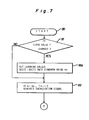
- a microcomputer 60 includes a read only memory or ROM which previously stores therein a main control program defined by flow charts shown in Figs. 7, 8, 10, 11 and 12 and also stores therein first and second interruption control programs defined by flow charts shown in Figs. 9 and 13, respectively.
- the microcomputer 60 cooperates with the A-D converters 50a - 50d, waveform shaper 50e and comparator 50g thereby to execute the main and first interruption control programs for control of the stepper motor 30a and to execute the second interruption control program for control of a relay 70.
- the computer 60 is connected to a DC voltage source in the form of a vehicle battery B through an ignition switch IG of the engine 10.
- the computer 60 is further connected to a back-up random access memory or RAM arranged to be maintained in its activated condition by power supply from a back-up power source 60a.
- the microcomputer 60 is arranged to initiate execution of the first interruption control program at each time when a timer provided in computer 60 completes measurement of a predetermined time duration, for instance, lmsec.
- the computer 60 is further arranged to initiate execution of the second interruption control program in response to opening of the ignition switch IG.
- the relay 70 is interposed between the DC voltage source B and the microcomputer 60, which relay 70' includes an electromagnetic coil 71 and a normally open switch 72 to be closed by energization of the electromagnetic coil 71.
- the air is drawn from the air cleaner 13 into the mixing chamber R and is mixed with the fuel drawn into the mixing chamber R from the fuel metering jet 29e through nozzle 28.
- the amount of air flowing into induction passage 21a is controlled by the axial displacement of throttle piston 24, and the amount of fuel is controlled by the axial displacement of needle valve element 27a.
- the air-fuel mixture formed in such a condition is supplied into the internal combustion engine 10 through the main throttle valve 25 and intake manifold 12.
- the microcomputer 60 When the iginition switch IG is closed, as previously described, the microcomputer 60 is activated to initiate execution of the main control program at step 80 in accordance with the flow charts of Figs. 7 and 8, and simultaneously the timer of microcomputer 60 starts repetitive measurement of the predetermined time duration of lmsec. Upon repetitive completion of measurement in the timer, the computer 60 initiates execution of the first interruption control program in accordance with the flow chart of Fig. 9 to increment a timer count value T by one repetitively.
- step 81 the computer 60 determines as to whether a state value F memorized in the back-up RAM prior to closing of the ignition switch IG is changed at this stage or not. If the answer is "Yes", the main control program proceeds to step 81a where the computer 60 sets respective learning values GK(0) - GK(7) as a standard value Ko.
- the standard value Ko is equal to, for instance, one.
- the learning values GK(0) - GK(7) each fluctuate on a basis of the standard value Ko and represent a compensation value for correcting the actual air-fuel ratio of the mixture to the optimum air-fuel ratio.
- the learning values GK(0) - GK(7) each may correspond with first to eighth stroke widths ⁇ L, ..., ⁇ L which are respectively determined by 1/8 of the entire length between the minimum and maximum stroke ends of piston 24.
- the first stroke width ⁇ L corresponds to the minimum stroke of piston 24, and the eighth stroke width AL corresponds to the maximum stroke of piston 24.
- step 82 the computer 60 acts to set a feedback correction value Af as the standard value Ko, to set the timer count value T as zero and to produce an energization signal for the electromagnetic coil 71 of relay 70.
- the feedback correction value Af fluctuates on a basis of the standard value Ko and represents a value for correcting the actual air-fuel ratio of the mixture to the optimum air-fuel ratio in consideration with oxygen concentration in exhaust gases.
- the electromagnetic coil 71 When applied with the energization signal from computer 60, the electromagnetic coil 71 is energized to close the switch 72 thereby to hold the power supply from DC voltage source B to computer 60 through switch 72.
- the computer 60 calculates a rotational speed EGR of engine 10 in response to rectangular wave signals from wave shaper 50e and temporarily memorizes the rotational speed EGR therein.
- the computer 60 receives digital signals respectively from A-D converters 50a - 50d and a low or high level signal from comparator 50g to temporarily memorize values of the digital signals as the air temperature THA, intake manifold pressure PIM, throttle opening degree SRT and cooling water temperature THW and to temporarily memorize a level of the high or low level signal as an oxygen concentration level OHL.
- the computer 60 calculates an amount Q of the air flow on a basis of the following equation (1) in accordance with the memorized rotational speed EGR and intake manifold negative pressure PIM to temporarily memorize the calculated amount Q of the air flow.
- K is a propotional constant.
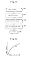
- the computer 60 calculates a stroke length LFT of piston 24 on a basis of a characteristic curve R 4 (see Fig. 14) in accordance with the calculated amount Q of the air flow and temporarily memorizes the calculated stroke length LFT.
- the characteristic curve 1 4 represents a relationship between the amount Q of the air flow and the stroke length LFT of piston 24 which is previously stored in the ROM of computer 60.
- the stroke length LFT is calculated as zero, and the amount Q of the air flow is substantially proportional to the cross-sectional area defined by the characteristic curve l 1 of Fig. 5 since the intake manifold negative pressure PIM is substantially maintained in a constant value.
- the computer 60 calculates a water temperature compensation value Aw in accordance with the memorized water temperature THW and temporarily memorizes the compensation value Aw.
- the water temperature compensation value Aw represents a value for correcting the actual air-fuel ratio of the mixture to an optimum air-fuel ratio and fluctuates on a basis of the standard value Ko.
- the computer 60 determines on a basis of the memorized throttle opening angle SRT, intake manifold negative pressure PIM, cooling water temperature THW and oxygen concentration level OHL as to whether a condition for feedback control of the air-fuel ratio is satisfied or not.
- the condition for feedback control of the air-fuel ratio is satisfied by the fact that the exhaust gas oxygen sensor 40f is maintained in its activated condition at a higher range of water temperature SRT during operative condition of engine 10 except the full load and idle conditions.
- the computer 60 acts at step 87 to set the feedback correction value Af equal to the standard value Ko and causes the main control program to proceed to a routine 88 for calculation of a learning correction value GK, as shown in Figs. 8 and 10.
- the computer 60 acts at step 88b to divide the stroke length LFT by the stroke width AL thereby to set the divided value )LFT/ ⁇ L) equal to a value LFN.
- the computer 60 corrects the value LFN into an integer INT (LFN) to set the same integer equal to a stroke width number N.
- the computer 60 determines a "No" answer at step 88d to calculate the learning correction value GK based on the following equation (2) at step 88e.
- GK(N) corresponds to one of GK(0) - GK(7) and where ⁇ GK (N + 1) - G(K) ⁇ (LFN - N) acts a role as interpolation for GK(N) to thereby ensure smooth change of GK even if the number of all the stroke widths ⁇ L, .... , ⁇ L is small.
- the standard amount SB of air bleed indicates a standard amount of air flowing through the air bleed passage 21f.
- the optimum rotary step number So of motor 30a corresponds with an optimum amount of air bleed flowing into the fuel metering jet 29e through the air bleed passage 21f.
- the reference character Kl indicates a constant which is available for converting each of the standard amount SB of air bleed, feedback correction value Af, learning correction value GK and water temperature Aw into a rotary step number of motor 30a.
- 3Ko acts a role as a correction factor for rendering into the standard value Ko the total 4Ko caused by addition of the standard amount SB of air bleed, feedback correction value Af, learning correction value CK and water temperature Aw.
- the computer 60 causes the main control program to proceed to step 90.
- the computer 60 produces a rotation signal the value of which represents a difference between the optimum rotary step number So and the actual rotary step number S.
- the motor 30a of drive mechanism 30 When applied with the rotation signal from computer 60, the motor 30a of drive mechanism 30 is activated to rotate the rotor 33 in a forward direction in accordance with the value of the rotation signal thereby to cause axial displacement of the needle valve element 36 against spring 37. This results in an increase of the cross-section of the air bleed passage 21f at valve seat 21g. Thus, the amount of air flowing into fuel metering jet 29e through air bleed passage 21f is controlled in accordance with the axial displacement of needle valve element 36.
- the computer 60 causes the main control program to proceed to a routine 91 for calculation of the feedback correction value Af (see Figs. 8 and 11). Then, the computer 60 initiates execution of the routine 91 at step 91a to determine at the following step 91b as to whether or not the timer count value T is larger than a predetermined value Tl previously memorized in the ROM of computer 60. If the answer is "No" at step 91b, the computer 60 ends execution of the routine 91 at step 91c.
- the computer 60 determines at the following step 91d as to whether or not the oxygen concentration level OHL is high or not. If the answer at step 91d is "Yes”, the routine 91 proceeds to step 91e where the computer 60 adds a value AAfl to the latest feedback correction value Af to update Af equal to (Af +AAfl). If the answer at step 91d is "No”, the routine 91 proceeds to step 91f where the computer 60 subtracts a value ⁇ Af2 from the latest feedback correction value Af to update Af equal to (Af - ⁇ Af2). In this embodiment, the values AAfl and ⁇ Af2 are previously stored in the ROM of computer 60.
- the value ⁇ Af2 is predetermined larger than the value AAfl.
- the main control program proceeds to the following step 92 at which the computer 60 determines as to whether or not the actual load acting on engine 10 is maintaimed in a predetermined learning range.
- the predetermined learning range is defined by the fact that a water temperature THA is higher than a predetermined temperature and that an air temperature THA is lower than a predetermined temperature. If a water temperature THA newly obtained at step 84 is lower than or equal to the predetermined temperature or an air temperature THA newly obtained at step 84 is higher than the predetermined temperature, the computer 60 determines a "No" answer at step 92 and causes the main control program to proceed to the routine 88.
- the computer 60 calculates an optimum rotary step number So in consideration with the feedback correction value Af, obtained at the routine 91, to generate a rotation signal at step 90 so as to drive the driving mechanism 30.
- the computer 60 advances the routine 91 through steps 91b, 91d, 91e and 91g repetitively to increase the optimum rotary step number So so as to render the mixture lean.
- the computer 60 advances the routine 91 through steps 91b, 91e, 91f and 91g repetitively to decrease the optimum rotary step number So so as to render the mixture rich. Additionally, owing to AAf2>AAfl, a speed in control of making the mixture rich is maintained higher than that in control of making the mixture lean. This is effective to prevent deterioration in exhaust gas components.
- the computer 60 determines an "Yes" answer at step 92 caused the main control program to proceed to a learning routine 93 for learning values GK(0) - GK(7).
- the computer 60 initiates execution of the learning roution 93 at step 93a to determine a value LFN and a stroke width number N respectively at steps 93b, 93c in the same manner as those at steps 88b, 88c of Fig. 10.
- the learning routine 93 proceeds to the following step 93d where the computer 60 calculates the learning value GK(N) on a basis of the following equation (4) in accordance with the value LFN, stroke width number N and feedback correcton value Af respectively obtained at steps 93b, 93c and routine 91.
- K2 is a weighted constant necessary for determining the changing rate of the learning value GK(N).
- the computer 60 subtracts the standard value Ko from the feedback correction value Af to multiply the subtracted value (Af - Ko) by a difference (N + 1 - LFN).
- the computer 60 multiplies the multiplied value ( Af - Ko).(N + 1 - LFN) by the weighted constant K2 and adds the multiplied value K2.(Af - Ko).(N + 1 - LFN) to the previous learning value GK (N) to set the added value equal to GK(N).
- the computer 60 determines a "No" answer at step 93e to calculate at step 93f the learning value GK(N + 1) on a basis of the following equation (5) in accordance with the value LFN, stroke width number N and feedback correction value Af respectively obtained at steps 93b, 93c and routine 91.
- the computer 60 subtracts the standard value Af from the feedback correction value Af to multiply the subtracted value (Af - Ko) by a difference (LFN - N).
- the computer 60 multiplies the multiplied value (Af - Ko).(LFN - N) by the weighted constant K2 and adds the multiplied value K2 ⁇ (Af - K0) ⁇ (LFN - N) to the previous learning value GK(N + 1) to set the added value equal to GK(N + 1).
- the main control program proceeds to the routine 88 where the computer 60 calculates an optimum rotary step number So in consideration with the learning values GK(N) and GK(N + 1) obtained at the routine 93 thereby to adjust the actual air-fuel ratio of the mixture to an optimum air-fuel ratio.
- the computer 60 When the ignition switch IG is opened to stop the engine 10 during arrest of the vehicle, the computer 60 is maintained in its activated condition by power supply across the switch 72 to execute the second interruption control program shown in Fig. 13. In this instance, the computer 60 starts execution of the second interruption control program at step 110.
- the computer 60 adds complement of GK(0) to the renewed learning value GK(0) to memorize the resultant value of the addition as a state value F.
- the computer 60 produces a rotation signal for rotating the stepper motor 30a toward the initial position.
- the stepper motor 30a is activated by the rotation signal from computer 60 to displace the needle valve element 36 to the initial position.
- the computer 60 puts out the energization signal to deenergize the electromagnetic coil 71 so as to open the switch 72.
- the computer 60 stops execution of the control programs at step 114.
- the back-up RAM of microcomputer 60 is maintained in its activated condition by power supply from the back-up source 60a to memorize therein the renewed learning values GK(0) - GK(7) and the state value F.
- the auxiliary throttle piston 24 is returned to its minimum stroke end under the biasing force of compression spring 26.
- one of the learning values GK(O) - GK(7) is selected in accordance with the value of stroke length LFT, it may be also selected in accordance with an amount Q of air flow corresponding to the stroke length LFT.
Landscapes
- Engineering & Computer Science (AREA)
- Chemical & Material Sciences (AREA)
- Combustion & Propulsion (AREA)
- Mechanical Engineering (AREA)
- General Engineering & Computer Science (AREA)
- Control Of The Air-Fuel Ratio Of Carburetors (AREA)
Applications Claiming Priority (2)
| Application Number | Priority Date | Filing Date | Title |
|---|---|---|---|
| JP15884885A JPS6220665A (ja) | 1985-07-18 | 1985-07-18 | 可変ベンチユリ型気化器のためのエアブリ−ド量制御装置 |
| JP158848/85 | 1985-07-18 |
Publications (2)
| Publication Number | Publication Date |
|---|---|
| EP0209389A2 true EP0209389A2 (de) | 1987-01-21 |
| EP0209389A3 EP0209389A3 (de) | 1987-11-25 |
Family
ID=15680727
Family Applications (1)
| Application Number | Title | Priority Date | Filing Date |
|---|---|---|---|
| EP86305509A Withdrawn EP0209389A3 (de) | 1985-07-18 | 1986-07-17 | Elektrisches Nebenluftventilsteuerungssystem für Vergaser |
Country Status (2)
| Country | Link |
|---|---|
| EP (1) | EP0209389A3 (de) |
| JP (1) | JPS6220665A (de) |
Cited By (6)
| Publication number | Priority date | Publication date | Assignee | Title |
|---|---|---|---|---|
| GB2194079A (en) * | 1986-08-13 | 1988-02-24 | Fuji Heavy Ind Ltd | Air-fuel ratio control system for an automotive engine |
| GB2203569A (en) * | 1987-03-11 | 1988-10-19 | Hitachi Ltd | Control apparatus for internal combustion engine |
| GB2241355A (en) * | 1990-02-10 | 1991-08-28 | Bosch Gmbh Robert | Controlling electromagnetic valve of a fuel pump |
| FR2684720A1 (fr) * | 1991-12-06 | 1993-06-11 | Honda Motor Co Ltd | Dispositif d'echappement pour un moteur a combustion interne. |
| EP0678662A3 (de) * | 1994-03-15 | 1998-09-16 | Yamaha Hatsudoki Kabushiki Kaisha | Verfahren und Vorrichtung zur Steuerung eines gasgespeisten Verbrennungsmotors |
| EP3330525A1 (de) * | 2016-12-02 | 2018-06-06 | Yamabiko Corporation | Tragbare motorarbeitsmaschine und darin eingebauter rotierender vergaser |
Family Cites Families (8)
| Publication number | Priority date | Publication date | Assignee | Title |
|---|---|---|---|---|
| FR2228158B1 (de) * | 1973-05-04 | 1977-08-19 | Sibe | |
| GB1554234A (en) * | 1975-07-08 | 1979-10-17 | Bosch Gmbh Robert | Fuel supply systems for internal combustion engines |
| US4250856A (en) * | 1980-01-25 | 1981-02-17 | Abbey Harold | Fuel-air ratio automatic control system using variable venturi structure |
| IT1081383B (it) * | 1977-04-27 | 1985-05-21 | Magneti Marelli Spa | Apparecchiatura elettronica per il controllo dell'alimentazione di una miscela aria/benzina di un motore a combustione interna |
| JPS6060019B2 (ja) * | 1977-10-17 | 1985-12-27 | 株式会社日立製作所 | エンジンの制御方法 |
| DE2812442A1 (de) * | 1978-03-22 | 1979-10-04 | Bosch Gmbh Robert | Verfahren und einrichtung zum bestimmen von einstellgroessen bei brennkraftmaschinen |
| JPS582451A (ja) * | 1981-06-29 | 1983-01-08 | Aisan Ind Co Ltd | 定圧型気化器を有する内燃機関の空燃比制御装置 |
| JPS5859329A (ja) * | 1981-10-02 | 1983-04-08 | Nippon Denso Co Ltd | 空燃比制御方法 |
-
1985
- 1985-07-18 JP JP15884885A patent/JPS6220665A/ja active Pending
-
1986
- 1986-07-17 EP EP86305509A patent/EP0209389A3/de not_active Withdrawn
Cited By (11)
| Publication number | Priority date | Publication date | Assignee | Title |
|---|---|---|---|---|
| GB2194079A (en) * | 1986-08-13 | 1988-02-24 | Fuji Heavy Ind Ltd | Air-fuel ratio control system for an automotive engine |
| GB2194079B (en) * | 1986-08-13 | 1991-03-27 | Fuji Heavy Ind Ltd | Air-fuel ratio control system for an automotive engine |
| GB2203569A (en) * | 1987-03-11 | 1988-10-19 | Hitachi Ltd | Control apparatus for internal combustion engine |
| GB2203569B (en) * | 1987-03-11 | 1991-04-03 | Hitachi Ltd | Control apparatus for internal combustion engine |
| GB2241355A (en) * | 1990-02-10 | 1991-08-28 | Bosch Gmbh Robert | Controlling electromagnetic valve of a fuel pump |
| GB2241355B (en) * | 1990-02-10 | 1993-12-22 | Bosch Gmbh Robert | Method of and equipment for controlling actuation of an electromagnetic valve of a fuel pump |
| FR2684720A1 (fr) * | 1991-12-06 | 1993-06-11 | Honda Motor Co Ltd | Dispositif d'echappement pour un moteur a combustion interne. |
| EP0678662A3 (de) * | 1994-03-15 | 1998-09-16 | Yamaha Hatsudoki Kabushiki Kaisha | Verfahren und Vorrichtung zur Steuerung eines gasgespeisten Verbrennungsmotors |
| EP3330525A1 (de) * | 2016-12-02 | 2018-06-06 | Yamabiko Corporation | Tragbare motorarbeitsmaschine und darin eingebauter rotierender vergaser |
| US10202942B2 (en) | 2016-12-02 | 2019-02-12 | Yamabiko Corporation | Portable engine working machine and rotary carburetor incorporated therein |
| US10634095B2 (en) | 2016-12-02 | 2020-04-28 | Yamabiko Corporation | Portable engine working machine and rotary carburetor incorporated therein |
Also Published As
| Publication number | Publication date |
|---|---|
| EP0209389A3 (de) | 1987-11-25 |
| JPS6220665A (ja) | 1987-01-29 |
Similar Documents
| Publication | Publication Date | Title |
|---|---|---|
| US4416239A (en) | Electronic control system for an internal combustion engine with correction means for correcting value determined by the control system with reference to atmospheric air pressure | |
| US4402217A (en) | Electronic engine control system with checking unit for sensors and actuators therein | |
| US4524745A (en) | Electronic control fuel injection system for spark ignition internal combustion engine | |
| US5699778A (en) | Fuel evaporative emission suppressing apparatus | |
| US4495921A (en) | Electronic control system for an internal combustion engine controlling air/fuel ratio depending on atmospheric air pressure | |
| EP0135176B1 (de) | Motorsteuerungsvorrichtung | |
| EP0511701A1 (de) | Verfahren und Vorrichtung zum Einstellen des Ansaugluftstroms eines Motors | |
| US5611309A (en) | Throttle valve control system for internal combustion engines | |
| EP0053464A2 (de) | Elektronisch gesteuertes Kraftstoffeinspritzsystem | |
| US4933863A (en) | Control systems for internal combustion engines | |
| EP0239095A2 (de) | Methode und System zur Steuerung von Innen-Verbrennungsmaschinen | |
| JPH073211B2 (ja) | 燃料蒸発ガス排出抑止装置 | |
| US5345912A (en) | Method and device for controlling a carburetor | |
| GB1601384A (en) | Electronic apparatus for feed control of air-gasoline mixture in internal combustion engines | |
| US5090389A (en) | Fuel delivery control apparatus for engine operable on gasoline/alcohol fuel blend | |
| US5311852A (en) | Method for detecting fuel blending ratio | |
| EP0209389A2 (de) | Elektrisches Nebenluftventilsteuerungssystem für Vergaser | |
| JPH0135170B2 (de) | ||
| US4825833A (en) | Engine control apparatus | |
| US5163407A (en) | Method for detecting fuel blending ratio | |
| US5655507A (en) | Evaporated fuel purge device for engine | |
| US5197451A (en) | Method for detecting fuel blending ratio | |
| US4450680A (en) | Air/fuel ratio control system for internal combustion engines, having secondary air supply control | |
| US4380988A (en) | Air/fuel ratio control system for internal combustion engines, having exhaust gas recirculation control function | |
| US5722368A (en) | Method and apparatus for adjusting the intake air flow rate of an internal combustion engine |
Legal Events
| Date | Code | Title | Description |
|---|---|---|---|
| PUAI | Public reference made under article 153(3) epc to a published international application that has entered the european phase |
Free format text: ORIGINAL CODE: 0009012 |
|
| AK | Designated contracting states |
Kind code of ref document: A2 Designated state(s): DE GB |
|
| PUAL | Search report despatched |
Free format text: ORIGINAL CODE: 0009013 |
|
| AK | Designated contracting states |
Kind code of ref document: A3 Designated state(s): DE GB |
|
| 17P | Request for examination filed |
Effective date: 19880122 |
|
| 17Q | First examination report despatched |
Effective date: 19880429 |
|
| STAA | Information on the status of an ep patent application or granted ep patent |
Free format text: STATUS: THE APPLICATION IS DEEMED TO BE WITHDRAWN |
|
| 18D | Application deemed to be withdrawn |
Effective date: 19880909 |
|
| RIN1 | Information on inventor provided before grant (corrected) |
Inventor name: ANDO, TSUNEOC/O AISAN KOGYO KABUSHIKI KAISHA Inventor name: KASUYA, KAZUSATOC/O AISAN KOGYO KABUSHIKI KAISHA |