EP0209393A2 - Tiefgezogener Behälter und Verfahren zu dessen Herstellung - Google Patents
Tiefgezogener Behälter und Verfahren zu dessen Herstellung Download PDFInfo
- Publication number
- EP0209393A2 EP0209393A2 EP86305536A EP86305536A EP0209393A2 EP 0209393 A2 EP0209393 A2 EP 0209393A2 EP 86305536 A EP86305536 A EP 86305536A EP 86305536 A EP86305536 A EP 86305536A EP 0209393 A2 EP0209393 A2 EP 0209393A2
- Authority
- EP
- European Patent Office
- Prior art keywords
- vessel
- steel
- draw
- foil
- deep
- Prior art date
- Legal status (The legal status is an assumption and is not a legal conclusion. Google has not performed a legal analysis and makes no representation as to the accuracy of the status listed.)
- Granted
Links
Images

Classifications
-
- B—PERFORMING OPERATIONS; TRANSPORTING
- B32—LAYERED PRODUCTS
- B32B—LAYERED PRODUCTS, i.e. PRODUCTS BUILT-UP OF STRATA OF FLAT OR NON-FLAT, e.g. CELLULAR OR HONEYCOMB, FORM
- B32B38/00—Ancillary operations in connection with laminating processes
- B32B38/12—Deep-drawing
-
- B—PERFORMING OPERATIONS; TRANSPORTING
- B32—LAYERED PRODUCTS
- B32B—LAYERED PRODUCTS, i.e. PRODUCTS BUILT-UP OF STRATA OF FLAT OR NON-FLAT, e.g. CELLULAR OR HONEYCOMB, FORM
- B32B15/00—Layered products comprising a layer of metal
- B32B15/04—Layered products comprising a layer of metal comprising metal as the main or only constituent of a layer, which is next to another layer of the same or of a different material
- B32B15/08—Layered products comprising a layer of metal comprising metal as the main or only constituent of a layer, which is next to another layer of the same or of a different material of synthetic resin
-
- B—PERFORMING OPERATIONS; TRANSPORTING
- B32—LAYERED PRODUCTS
- B32B—LAYERED PRODUCTS, i.e. PRODUCTS BUILT-UP OF STRATA OF FLAT OR NON-FLAT, e.g. CELLULAR OR HONEYCOMB, FORM
- B32B15/00—Layered products comprising a layer of metal
- B32B15/04—Layered products comprising a layer of metal comprising metal as the main or only constituent of a layer, which is next to another layer of the same or of a different material
- B32B15/08—Layered products comprising a layer of metal comprising metal as the main or only constituent of a layer, which is next to another layer of the same or of a different material of synthetic resin
- B32B15/085—Layered products comprising a layer of metal comprising metal as the main or only constituent of a layer, which is next to another layer of the same or of a different material of synthetic resin comprising polyolefins
-
- B—PERFORMING OPERATIONS; TRANSPORTING
- B32—LAYERED PRODUCTS
- B32B—LAYERED PRODUCTS, i.e. PRODUCTS BUILT-UP OF STRATA OF FLAT OR NON-FLAT, e.g. CELLULAR OR HONEYCOMB, FORM
- B32B15/00—Layered products comprising a layer of metal
- B32B15/18—Layered products comprising a layer of metal comprising iron or steel
-
- B—PERFORMING OPERATIONS; TRANSPORTING
- B32—LAYERED PRODUCTS
- B32B—LAYERED PRODUCTS, i.e. PRODUCTS BUILT-UP OF STRATA OF FLAT OR NON-FLAT, e.g. CELLULAR OR HONEYCOMB, FORM
- B32B27/00—Layered products comprising a layer of synthetic resin
- B32B27/18—Layered products comprising a layer of synthetic resin characterised by the use of special additives
- B32B27/20—Layered products comprising a layer of synthetic resin characterised by the use of special additives using fillers, pigments, thixotroping agents
-
- B—PERFORMING OPERATIONS; TRANSPORTING
- B32—LAYERED PRODUCTS
- B32B—LAYERED PRODUCTS, i.e. PRODUCTS BUILT-UP OF STRATA OF FLAT OR NON-FLAT, e.g. CELLULAR OR HONEYCOMB, FORM
- B32B27/00—Layered products comprising a layer of synthetic resin
- B32B27/32—Layered products comprising a layer of synthetic resin comprising polyolefins
-
- B—PERFORMING OPERATIONS; TRANSPORTING
- B32—LAYERED PRODUCTS
- B32B—LAYERED PRODUCTS, i.e. PRODUCTS BUILT-UP OF STRATA OF FLAT OR NON-FLAT, e.g. CELLULAR OR HONEYCOMB, FORM
- B32B7/00—Layered products characterised by the relation between layers; Layered products characterised by the relative orientation of features between layers, or by the relative values of a measurable parameter between layers, i.e. products comprising layers having different physical, chemical or physicochemical properties; Layered products characterised by the interconnection of layers
- B32B7/04—Interconnection of layers
- B32B7/12—Interconnection of layers using interposed adhesives or interposed materials with bonding properties
-
- B—PERFORMING OPERATIONS; TRANSPORTING
- B65—CONVEYING; PACKING; STORING; HANDLING THIN OR FILAMENTARY MATERIAL
- B65D—CONTAINERS FOR STORAGE OR TRANSPORT OF ARTICLES OR MATERIALS, e.g. BAGS, BARRELS, BOTTLES, BOXES, CANS, CARTONS, CRATES, DRUMS, JARS, TANKS, HOPPERS, FORWARDING CONTAINERS; ACCESSORIES, CLOSURES, OR FITTINGS THEREFOR; PACKAGING ELEMENTS; PACKAGES
- B65D1/00—Rigid or semi-rigid containers having bodies formed in one piece, e.g. by casting metallic material, by moulding plastics, by blowing vitreous material, by throwing ceramic material, by moulding pulped fibrous material or by deep-drawing operations performed on sheet material
- B65D1/22—Boxes or like containers with side walls of substantial depth for enclosing contents
- B65D1/26—Thin-walled containers, e.g. formed by deep-drawing operations
- B65D1/28—Thin-walled containers, e.g. formed by deep-drawing operations formed of laminated material
-
- B—PERFORMING OPERATIONS; TRANSPORTING
- B32—LAYERED PRODUCTS
- B32B—LAYERED PRODUCTS, i.e. PRODUCTS BUILT-UP OF STRATA OF FLAT OR NON-FLAT, e.g. CELLULAR OR HONEYCOMB, FORM
- B32B2264/00—Composition or properties of particles which form a particulate layer or are present as additives
- B32B2264/10—Inorganic particles
- B32B2264/102—Oxide or hydroxide
-
- B—PERFORMING OPERATIONS; TRANSPORTING
- B32—LAYERED PRODUCTS
- B32B—LAYERED PRODUCTS, i.e. PRODUCTS BUILT-UP OF STRATA OF FLAT OR NON-FLAT, e.g. CELLULAR OR HONEYCOMB, FORM
- B32B2323/00—Polyalkenes
- B32B2323/10—Polypropylene
-
- Y—GENERAL TAGGING OF NEW TECHNOLOGICAL DEVELOPMENTS; GENERAL TAGGING OF CROSS-SECTIONAL TECHNOLOGIES SPANNING OVER SEVERAL SECTIONS OF THE IPC; TECHNICAL SUBJECTS COVERED BY FORMER USPC CROSS-REFERENCE ART COLLECTIONS [XRACs] AND DIGESTS
- Y10—TECHNICAL SUBJECTS COVERED BY FORMER USPC
- Y10S—TECHNICAL SUBJECTS COVERED BY FORMER USPC CROSS-REFERENCE ART COLLECTIONS [XRACs] AND DIGESTS
- Y10S220/00—Receptacles
- Y10S220/917—Corrosion resistant container
-
- Y—GENERAL TAGGING OF NEW TECHNOLOGICAL DEVELOPMENTS; GENERAL TAGGING OF CROSS-SECTIONAL TECHNOLOGIES SPANNING OVER SEVERAL SECTIONS OF THE IPC; TECHNICAL SUBJECTS COVERED BY FORMER USPC CROSS-REFERENCE ART COLLECTIONS [XRACs] AND DIGESTS
- Y10—TECHNICAL SUBJECTS COVERED BY FORMER USPC
- Y10T—TECHNICAL SUBJECTS COVERED BY FORMER US CLASSIFICATION
- Y10T428/00—Stock material or miscellaneous articles
- Y10T428/12—All metal or with adjacent metals
- Y10T428/12431—Foil or filament smaller than 6 mils
-
- Y—GENERAL TAGGING OF NEW TECHNOLOGICAL DEVELOPMENTS; GENERAL TAGGING OF CROSS-SECTIONAL TECHNOLOGIES SPANNING OVER SEVERAL SECTIONS OF THE IPC; TECHNICAL SUBJECTS COVERED BY FORMER USPC CROSS-REFERENCE ART COLLECTIONS [XRACs] AND DIGESTS
- Y10—TECHNICAL SUBJECTS COVERED BY FORMER USPC
- Y10T—TECHNICAL SUBJECTS COVERED BY FORMER US CLASSIFICATION
- Y10T428/00—Stock material or miscellaneous articles
- Y10T428/12—All metal or with adjacent metals
- Y10T428/12431—Foil or filament smaller than 6 mils
- Y10T428/12438—Composite
-
- Y—GENERAL TAGGING OF NEW TECHNOLOGICAL DEVELOPMENTS; GENERAL TAGGING OF CROSS-SECTIONAL TECHNOLOGIES SPANNING OVER SEVERAL SECTIONS OF THE IPC; TECHNICAL SUBJECTS COVERED BY FORMER USPC CROSS-REFERENCE ART COLLECTIONS [XRACs] AND DIGESTS
- Y10—TECHNICAL SUBJECTS COVERED BY FORMER USPC
- Y10T—TECHNICAL SUBJECTS COVERED BY FORMER US CLASSIFICATION
- Y10T428/00—Stock material or miscellaneous articles
- Y10T428/13—Hollow or container type article [e.g., tube, vase, etc.]
- Y10T428/1352—Polymer or resin containing [i.e., natural or synthetic]
- Y10T428/1355—Elemental metal containing [e.g., substrate, foil, film, coating, etc.]
- Y10T428/1359—Three or more layers [continuous layer]
Definitions
- the present invention relates to a deep-draw-formed vessel prepared from a laminate of an iron or steel foil and a plastic material. More particularly, the present invention relates to a deep-draw-formed vessel excellent in corrosion resistance, shape-retaining property and easy disposability. Furthermore, the present invention relates to an improvement of the deep-drawability of a laminate comprising an iron or steel foil and a resin film.
- the packaging material for a vessel or lid there have been used various single materials such as metals, plastics, paper, glass and ceramics, and composite materials comprising at least two of these single materials.
- metal materials are most preferred.
- a packaging material having an easy disposability a laminate comprising a metal foil and a resin film is widely used in the field of sealed vessels or sealed lids. Almost all of commercially available laminates for vessels or lids comprise an aluminum foil as the substrate.
- an aluminum foil is excellent in appearance characterisitcs and flexibility, even in the state covered with an organic resin, troubles such as corrosion, i.e., pitting, and peeling of the covering layer are caused by a content containing a salt such as sodium chloride at a hihg concentration or a content containig an organic acid, and such defects as leak of the content and reduction of the preserving property are brought about.
- a content containing a salt such as sodium chloride at a hihg concentration or a content containig an organic acid
- foils composed mainly of iron or steel, such as an iron foil, a steel foil and a tinplate foil.
- use of these foils as the packaging material involves problems to be solved. Namely, rusting is readily caused in iron and steel, and during the preparation of a packaged article or during the storage, rusting is caused and drastic reduction of the appearance characteristics or commercial value often occurs. Furthermore, dissolution of iron or incorporation of rust results in drastic reduction of the property of retaining the flavor of the content.
- an iron foil or steel foil is smaller than the thickness of a steel plate, the iron or steel foil is poor in drawability and formability, and during the draw-forming operation, the foil is wrinkled or broken and it is impossible to form a vessel. This defect becomes conspicuous when an organic resin covering layer having a relatively large thickness is applied to the iron or steel foil so as to improve the corrosion resistance or rust resistance of the foil.
- Another object of the present invention is to provide a deep-draw-formed vessel of a laminate of a steel iron foil and a plastic film, which is excellent in the combination of corrosion resistance, shape-retaining property and easy disposability.
- Still another object of the present invention is to provide a process for preparing a faultless and excellent deep-draw-formed vessel as mentioned above from a steel or iron foil.
- a further object of the present invention is to provide a process for deep-draw-forming a steel or iron foil into a vessel, in which wrinkling or breaking (edge cutting) is effectively prevented.
- a still further object of the present invention is to provide a deep-draw-formed vessel of a steel or iron foil in which rusting or dissolution of iron is effectively prevented and the commercial value is increased.
- a deep-draw-formed vessel which is prepared by deep-draw-forming a laminate comprising a steel or iron foil and a plastic film formed on each surface of the steel or iron foil through a layer of an adhesive having an adhesive force of at least 600 g/15 mm of width and an elastic modulus of 50 to 10000 kg/cm 2 .
- a process for the preparation of deep-draw-formed vessels which comprises deep-draw-forming a laminate comprising a steel or iron foil and thermoplastic films covering both the surfaces of the steel or iron foil, wherein an inorganic filler is incorporated at least in the film layer to be located on the inner face side of a final vessel.
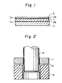
- reference numeral 1 represents a steel foil as the substrate
- reference numerals 2a and 2b represent a surface-treated layer
- reference numerals 3a and 3b represent an adhesive layer
- reference numeral 4 represents a thermoplastic resin film on the inner face side, especially an inorganic filler-incorporated resin film
- reference numeral 5 represents a thermoplastic resin film on the outer face side
- reference numeral 10 represents a laminate
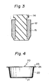
- reference numeral 11 represents a blank holder
- reference numeral 12 represents a punch
- reference numeral 13 represents a die
- reference numeral 14 represents a metal core of the punch
- reference numeral 15 represents a rubber
- reference numeral 20 represents a total vessel
- reference numeral 21 represents a bottom of the vessel
- reference numeral 22 represents a side wall
- reference numeral 23 represents a flange
- reference numeral 24 represents a cut edge
- reference numeral 25 represents a curled portion.
- the present invention is based on the finding that if an adhesive having an adhesive force of at least 600 g/15 mm of width, especially at least 1000 g/15 mm of width, and an elastic modulus of 50 to 10000 kg/cm , especially 200 to 9000 kg/cm 2 , as measured at room temperature is used as the adhesive to be interposed between the steel or iron foil and the plastic film, the above-mentioned interlaminar peeling after the deep-draw-forming operation is effectively prevented.
- the adhesive force and elastic modulus referred to herein are values determined according to methods described below.
- the plastic film layer should flow according as the flow of the surface of the steel or iron foil.
- the adhesive layer used in the present invention should exert an adhesive force of at least 600 g/15 mm of width to the combination of the steel or iron foil and the plastic film. If the adhesive force is smaller than the above-mentioned lower limit value, deep-draw forming per se becomes difficult, or even if deep-draw forming is possible, peeling is caused by the internal stress left in the surface of the plastic film during the retort sterilization or storage after the deep-draw-forming operation.
- the elastic modulus of the adhesive has serious influences on the peeling tendency after deep-draw forming of a laminate of a steel or iron foil and a plastic film.
- deformation of the plastic film caused by deep-draw forming in the side face portion of a vessel comprises substantially expansion in the axial direction of the vessel and compression deformation in the circumferential direction of the vessel. Accordingly, the plastic film on the surface of the vessel has an internal stress moderating these deformations. If the elastic modulus is too low and below the above-mentioned range, bonding cannot resist the above-mentioned internal stress and peeling is caused between the steel or iron foil and the plastic film.
- the elastic modulus is too high and exceeds the range specified in the present invention, fracture is caused in the adhesive layer at the stage of plastic deformation during the forming operation, resulting in occurrence of interlaminar peeling.
- the elastic modulus of the adhesive layer within the above-mentioned range, fracture of the adhesive layer at the stage of plastic deformation during the forming operation is prevented, and simultaneously, bonding can resist the internal stress left on the surface of the plastic film after the forming operation and interlaminar peeling between the steel or iron foil and the plastic film can be effectively prevented.
- the present invention by thus enhancing the adhesion of the plastic film to the steel or iron foil, occurrence of such troubles as rusting, pitting and dissolution of iron into the content can be completely prevented. Furthermore, since the steel or iron foil has a higher corrosion resistance to salts than an aluminum foil, it will be readily understood that there can be provided a dealed packaging vessel having a good preserving property to many foods containing salts.
- the rigidity of the steel or iron foil is higher than foils of other metals, it will be understood that there can be provided a light-weight vessel excellent in the shape-retaining property. Since the steel or iron foil sued in the present invention has ordinarily a thickness smaller than 100 ⁇ m, the steel or iron foil is light in the weight and can be easily crushed and can also be easily ashed (oxidized to iron oxide) by incineration. Accordingly, the formed vessel is easily disposable.
- the steel or iron foil used in the present invention may have a surface-treated layer on the surface thereof.
- This surface-treated layer may be a known surface-treated layer formed by a deposition treatment, an electrolytic treatment, a formation treatment or a chemical treatment, as described hereinafter.
- a deposition treatment for formation of the thermoplastic film used as the covering layer, any of materials having a film-forming property and a water resistance can be used, as described in detail hereinafter.
- Any of inorganic pigments and inorganic extender pigments can be used as the inorganic filler.
- the present invention is further characterized in that in draw-forming a steel or iron foil, it is used in the form of a laminate comprising thermoplastic resin films laminated on both the surfaces and an inorganic filler is incorporated in the film layer located on the inner face side of a final vessel.
- an inorganic filler is incorporated in the film layer located on the inner face side of a final vessel.
- the maximum value of R at which draw-forming is possible is called "critical draw ratio". The larger is the critical draw ratio, more larger is the draw-forming depth.
- an iron or steel foil is much inferior to a steel plate in the deep-drawability and formability.
- the reason is that wrinkles are formed during the draw-forming operation even if the blank holding force is increased so as to prevent formation of wrinkles, the blank holding force is not sufficiently transferred to the foil surface through an organic covering. Furthermore, if the blank holding force is excessively increased, formation of a vessel becomes impossible because the strength of the iron or steel foil is small.
- the inorganic filler in the organic resin covering hardens the organic resin covering and if the organic filler is incorporated in the organic resin covering, the blank holding force is efficiently transferred to the foil and therefore, it is considered that a wrinkle- free draw-formed vessel can be conveniently prepared.
- the inorganic filler-incorporated covering corrosion of the iron or steel foil by a corrosive component can be greatly controlled and for example, formation of hydrogen is substantially controlled. Accordingly, the shelf life of a formed vessel is considerably prolonged and even if rusting is caused in the iron or steel foil during long-period storage, the rust is hidden and a good appearance characteristic can be maintained for a long time, with the result that the commercial value is increased.
- thermoplastic resin film inner face layer 4 is formed on the inner face side (the lower side in Fig. 1) of a final vessel through an adhesive layer 3a.
- thermoplastic film outer face layer 5 is formed through an adhesive layer 3b, if necessary.
- an inorganic filler be incorporated at least in the resin film inner face layer 4, especially in both the film layers 4 and 5.
- the reason why a steel or iron foil is used in the present invention is that the pitting speed of the steel or iron foil to a content containing sodium chloride or the like is much lower than that of an aluminum foil. Accordingly, the corrosion resistance and gas barrier property of the resulting vessel can be prominently improved.
- the steel or iron foil has a Young's modulus about 2.5 times the Young's modulus of the aluminum foil, and therefore, satisfactory strength and shape-retaining property can be obtained with a relatively small thickness. Furthermore, the steel or iron foil is cheaper than the aluminum foil and the cost of a packaging material can be reduced.
- the steel or iron foil should have a thickness of 10 to 120 ⁇ m, especially 30 to 100 ⁇ m. If the thickness is smaller than 10 ⁇ m, it is difficult to obtain a foil free of defects such as pinholes, and a good barrier property to gases and steam can hardly be obtained. If the thickness is larger than 120 ⁇ m, the final vessel is too rigid and the disposal becomes difficult, or economical advantages are lost.
- an iron foil is used, and in the case where a rigidity or mechanical strength sufficiently to retain the shape is required, a steel foil is used.
- the iron foil is prepared by depositing iron on the surface of a metal substrate as the cathode from an electrolyte containing as the main contituent ferric chloride, ferric sulfate or the like and peeling the formed film from the surface of the substrate.
- the purity of the iron foil is very high (an Fe content of 99.97% or more) and the corrosion resistance is excellent, and the iron foil is ductile as compared with the steel foil.
- the iron foil has a columnar crystal structure in which crystals grow in the thickness direction, while the steel foil has a structure in which crystal grains are elongated in the rolling direction.
- Either a ductile steel foil or a full-hard steel foil can be formed.
- the former steel foil can be obtained by annealing a cold-rolled steel plate, subjecting it to secondary cold rolling, annealing it again and, if necessary, subjecting the resulting foil to at least one post treatment selected from zinc deposition, tin deposition, nickel deposition, electrolytic chromate treatment and chromate treatment.
- the latter steel foil is prepared by subjecting a cold-rolled steel plate to annealing and secondary cold rolling and, if necessary, subjecting the formed foil to at least one post treatment selected from zinc deposition, tin deposition, nickel deposition, electrolytic chromate treatment and chromate treatment.
- a full-hard steel provided with a metal plating layer can be prepared by annealing a cold-rolled steel plate, subjecting it to the temper treatment, depositing a metal on the surface and subjecting the metal-deposited steel plate to secondary cold rolling.
- the ductile steel foil has a tensile strength of 30 to 50 kg/mm and an elongation of 15 to 35%
- the full-hard iron foil has a tensile strength of 40 to 60 kg/mm 2 and an elongation of 1 to 15%
- the iron foil has a tensile strength of 30 to 50 kg/mm 2 and an elongation of 2 to 10%. It is ordinarily preferred that a steel foil be used.
- a surface-treated layer comprising a metal plating layer or a metal plating layer and a chromate layer formed thereon be formed on the iron or steel foil.
- the organic resin covering is effective for preventing direct contact between the content and the iron or steel foil, but the organic resin covering allows considerable permeation of hydrogen ions from an organic acid or the like contained in a highly corrosive content and slight permeation of anions contained in salts, such as chloride ions. Accordingly, peeling of the organic resin covering is readily caused in the interface between the organic resin covering and the foil, and once this peeling is caused, rusting, dissolution of iron or corrosion such as pitting is easily advanced from the peeled portion.
- the metal plating layer acts as a barrier layer to the above-mentioned corrosive components and the metal plating layer enhances the adhesion between the iron or steel foil and the organic resin covering layer. If a chromate layer is formed on the metal plating layer, this adhesion is further improved.
- Metals which are more ductile than iron and have an anticorrosive effect to iron such as Ni, Sn, Zn and AI, are typically used for the metal plating layer.
- a plating layer composed solely of a member selected from these metals is excellent in the anticorrosive effect and has a good draw-formability, and when the iron or steel foil is cut, the metal of the plating layer flows into the cut edge portion to protect the cut edge portion and control occurrence of rusting from the cut edge portion. This is an unexpected and novel functional effect.
- the Vickers hardness Hv of the metal plating layer be lower than 500, especially lower than 400, and the amount coated of the metal be 0.1 to 15 g/m 2 , especially 0.2 to 12 g/m 2 . If a metal having a hardness exceeding the above range is used, the metal of the plating layer does not flow to the cut edge portion when the iron or steel foil is cut, and an effect of preventing rusting is not attained. If the amount coated of the metal is too small and below the above-mentioned range, the barrier effect to corrosive components and the anticorrosive effect are insufficient, and the effect of preventing rusting in the cut edge portion is not attained. Use of the metal in a covered amount exceeding the above-mentioned range is economically disadvantageous and the advantages attained by use of the iron or steel foil are cancelled.
- a nickel plating layer is especially excellent in the barrier effect to corrosive components, and a tin- plated iron or steel foil, that is, a tinplate foil, is easily available.
- a tin- plated iron or steel foil that is, a tinplate foil
- the tin layer may be a metallic tin layer, but in view of the adhesion of the organic resin covering layer it is preferred that the tin layer be a layer of a tin-iron alloy in which the Sn/Fe atom ratio be from 2 to 1.
- chromate layer there can be mentioned a chromium oxide layer composed mainly of hydrous chromium oxide in which the amount covered of Cr is 1 to 50 2 mg/m , especially 3 to 35 mg/m .
- This chromate layer is formed on the above-mentioned metal plating layer by knwon formation treatment and/or chemical treatment.
- a tin-free steel foil comprising a metallic chromium layer as the plating layer and a chromate layer formed thereon. It is preferred that this metallic chromium layer be present in an amount covered of 0.03 to 0.5 g/m , especially 0.05 to 0.3 g/m 2.
- the metal plating layer is not limited to a layer composed of a single metal but the layer may be composed of a plurality of metals.
- the metal plating layer may be a composite layer comprising an underplating layer of the above-mentioned ductile metal such as nickel and a top plating layer of metallic chromium formed thereon by the electrolytic chromate treatment, and a chromium oxide layer may be further formed thereon.
- any of film-forming resins that can be deep-draw-formed in the form of a laminate with a steel or iron foil can be optionally used for the plastic film in the present invention. Preferred examples are described below though resins that can be used are not limited to those exemplified below.
- the thickness of the thermoplastic resin film be 10 to 150 ⁇ m, especially 30 to 100 ⁇ m. If the thickness is too small and below the above range, the covering effect of the resin film against corrosion is likely lost, and if the thickness is too large and exceeds the above range, the draw-formability is degraded.
- the above-mentioned resin covering layers are formed on both the surfaces of the iron or steel foil. It is preferred that an inorganic filler be incorporated at least in the resin layer to be located on the inner face side of a final vessel, especially on both the resin layers.
- inorganic white pigments such as rutile titanium dioxide, anatase titanium dioxide, zinc flower and gloss white
- white extender pigments such as baryte, precipitated baryte sulfate, calcium carbonate, gypsum, precipitated silica, aerosil, talc, calcined clay, uncalcined caly, barium carbonate, alumina white, synthetic mica, natural mica, synthetic calcium silicate and magnesium carbonate, black pigments such as carbon black and magnetite, red pigments such as red iron oxide, yellow pigments such as sienna, and blue pigments such as ultramarine and cobalt blue.
- inorganic fillers that can be used in the present invention are not limited to those exemplified above.
- the average particle size of the inorganic filler be 0.05 to 20 um, and in view of the draw-formability, it is preferred that the specific gravity of the inorganic filler be 2.0 to 9.0. In view of the hiding and barrier properties, it is preferred that the hiding power determined according to JIS K-5101 be at least 50 cm 2 /g.
- Titanium dioxide especially rutile titanium dioxide, is preferred as the inorganic filler for attaining the objects of the present invention.
- this titanium dioxide shows a highest anticorrosive action against corrosion of the steel or iron foil by corrosive components, and titanium dioxide is excellent in the hiding power. Accordingly, if titanium dioxide is used, it is possible to keep a packaging vessel white permanently.
- the inorganic filler be incorporated in an amount of 2 to 50% by weight, especially 5 to 30% by weight, based on the resin, though the preferred amount differs to some extent according to the film thickness and the like. If the amount of the inorganic filler is too small and below the above-mentioned range, the effect of controlling formation of wrinkles by increasing the rigidity of the film layer is insufficient, and the corrosion resistance and hiding effect are not satisfactory. If the amount of the inorganic filler is too large and exceeds the above-mentioned range, the resin film becomes brittle, and at the draw-forming step, pinholes or cracks are readily formed or breaking or peeling is readily caused.
- the adhesive used in the present invention has the above-mentioned properties.
- An appropriate adhesive is selected according to the kind of the plastic film used while taking properties of the adhesive resin into consideration.
- isocyanate type adhesives and epoxy type adhesives especially polyester-urethane adhesives and polyester-epoxy-urethane adhesives.
- polyester-urethane adhesive there can be mentioned a product obtained by reacting a hydroxy-terminated polyester with a diisocyanate and crosslinking the obtained isocyanate-terminated polyester by water or a polyhydric alcohol as the crosslinking agent and a product obtained by reacting a polyhydric alcohol, a polybasic carboxylic acid and a diisocyanate and crosslinking the obtained hydroxy-terminated polyester urethane by a diisocyanate as the crosslinking agent.
- the latter adhesive is especially preferred.
- polybasic carboxylic acid constituting the polyester there can be mentioned succinic acid, adipic acid, sebacic acid and decane-carboxylic acid.
- polyhydric alcohol component there can be mentioned ethylene glycol, propylene glycol, butane-diol, glycerol, neopentyl glycol, erythritol, sorbitol and mannitol.
- diisocyanate there can be mentioned xylylene diisocyanate, tolylene diisocyanate, cyclohexane diisocyanate and isophorone diisocyanate.
- polyester-urethane adhesion of this type produces a strong adhesion bond, ordinarily an adhesive force of 1.4 to 1.8 kg/15 mm, between the steel or iron foil and the plastic film because of the presence of urethane groups, and since hard segments derived from the diisocyanate and soft segments derived from the polyester are present in the main chain, an elastic modulus within the above-mentioned range, especially an elastic modulus of 4000 to 9000 kg/cm 2 , is provided.
- the polyester-epoxy-urethane adhesive is a composition comprising a hydroxy-terminated polyester, an epoxy resin and a diisocyanate crosslinking agent.
- a hydroxy-terminated polyester an epoxy resin and a diisocyanate crosslinking agent.
- the polybasic carboxylic polyhydric alcohol and diisocyanate constituting the hydroxyl-terminated polyester, compounds described above can be used.
- An epoxy resin obtained by reacting bisphenol A with epichlorohydrin is used as the epoxy resin.
- the polyester-epoxy-urethane adhesive shows a high adhesive force similar to that of the above-mentioned polyester-urethane adhesive, and the elastic modulus is within a range of from 1020 to 5100 kg/cm 2 .
- Lamination and bonding of the steel or iron foil and the plastic film can be accomplished by coating a solution of the above-mentioned adhesive in an organic solvent on the surface of the steel or iron foil or the plastic film, evaporating the solvent and pressing the foil and the film. It is preferred that the amount coated of the adhesive be 4.0 to 8.0 g/m 2 .
- the deep-draw-forming operation can be easily accomplished by using the above-mentioned laminate as the material.
- a blank 10 obtained by cutting the above-mentioned laminate in predetermined size and shape is subjected to press forming between punch 12 and die 13 relatively movable in the axial direction in the state where the blank 10 is held by a blank holder 11, whereby a bottomed seamless cup is obtained.
- the critical draw ratio can be increased to about 2.4, though the critical draw ratio attainable by the conventional techniques is about 1.5 to about 2.0.
- One-staged forming operation is ordinarily sufficient, but if desired, the draw-forming operation may be performed in two stages or multiple stages.
- An ordinary metal punch can be used as the punch 12 for the draw-forming operation.
- a punch 12' comprising a metal core 14 and a surrounding operation side wall 15 of a rubber (Japanese Patent No. 1,130,414) as shown in Fig. 3 is used, formation of wrinkles can be further controlled.
- this vessel 20 comprises a bottom 21, a side wall 22 connected to the bottom vertically or in an upwardly exspansive manner and a flange 23 formed on the top end of the side wall 22.
- a cut edge 24 is present on the outer side of the flange 23, but since the steel or iron foil is covered with the metal plating layer, as described hereinabove, rusting is controlled. In case of a steel or iron foil, ordinarily, this cut edge is a sharp edge and the finger or the like is easily hurt.
- the resin covering layer having the above-mentioned thickness, the above risk can be completely obviated and a high safety is established for a packaging material including a steel or iron foil.
- this vessel comprises a bottom 21, a side wall 22 and a flange 23, as well as the vessel shown in Fig. 4, but in the vessel shown in Fig. 5, a curled portion 25 is formed on the outermost edge of the flange 23 by curling the laminate.
- Fig. 6 illustrates another example. In the vessel shown in Fig. 6, the curled portion 25 is located at the same level as the flange 23 or at a position lower than the position of the flange 23, whereby inclusion of the content in the heat-sealed portion is prevented.
- the shape of the bottomed of the vessel is not particularly critical, and any of circular, ellipsoidal, square, rectangular, hexagonal and octagonal shapes may be adopted.
- the vessel can be easily heat-sealed with a lid member.
- a laminate was cut into a test piece having a width of 15 mm and a length of about 100 to about 150 mm and open end was slightly peeled.
- the test piece was set in the form of T-peel so that the test piece was peeled at an angle of 90° and the peeling force was measured at a peeling speed of 300 mm/min by a universal tensile tester.
- a sample was coated on a Teflon plate and aged in a vacuum drier to obtain a test piece.
- the measurement was conducted on the test piece having a length of 3 cm, a width of 0.4 cm and a thickness of 0.01 to 0.03 cm within a measurement temperature range of from - 80°C to 80°C at a temperature-elevating speed of 3°C/min, a printing interval of 4°C and a measurement frequency of 110 Hz by using RHEOVIBRON Model DDV-III-EA supplied by Toyo Baldwin.
- the critical draw ratio was determined according to the method shown in Fig. 2, and the appearance was evaluated.
- the vessel stored in the same manner as described in (5-1) above was opened and the gas in the head space was collected on water.
- the amount of hydrogen in the gas was determined by gas chromatography according to the customary method.
- the amount of hydrogen is substantiallly in proportion to the amount of corrosion of the inner face of the vessel.
- a steel foil having a thickness of 75 ⁇ m was cathodically electrolyzed in an electrolytic chromate treatment bath (aqueous solution containing 60 g/1 of chromic anhydride, 0.2 g/l of sulfuric acid and 0.2 g/l of sodium silicofluoride) to form a surface-treated layer comprising 0.1 g/m 2 of a metallic chromium layer and 15 mg/m 2 of a chromate layer on each surface of the steel foil.
- a polyester-urethane adhesive (a) was coated on both the surfaces of the surface-treated steel foil in an amount coated of 5 to 6 g/m2.
- a corona- discharged polypropylene film containing 10% by weight of rutile titanium dioxide incorporated therein and having a thickness of 70 um was laminated on the surface to be located on the inner face side of a final vessel, and a similar polypropylene film having a thickness of 40 ⁇ m was laminated on the surface to be located on the outer face side of the final vessel.
- the so-obtained laminate was allowed to stand still at 50°C for 5 days to cure the adhesive.
- the adhesive force of the laminate was 1.4 to 1.8 kg/15 mm of width, and the elastic modulus of the adhesive was 7140 kg/cm 2 as measured at 25°C.
- the draw-formability was determined as described in (3) above, and a vessel was formed as described in (4) above and shown in Fig. 5 and was evaluated as described in (5) above.
- both the surfaces of a steel foil having a thickness of 40 ⁇ m were plated with 2.0 g/m 2 of nickel in a Watt bath (aqueous solution containing 240 g/l of nickel sulfate, 45 g/1 of nickel chloride and 30 g/l of boric acid), and the plated steel foil was cathodically electrolyzed in the above-mentioned electrolytic chromate treatment bath to form a surface-treated layer comprising 0.05 g/m 2 of a metallic chromium layer and 15 mg/m 2 of a chromate layer.
- An epoxy-phenolic laquer was coated and baked on one surface so that a coating layer having a thickness of 5 ⁇ m was formed, and a polypropylene film having a thickness of 50 ⁇ m was heat-bonded to the other surface through a maleic anhydride-modified polypropylene layer having a thickness of 10 ⁇ m and molten at 200°C. Then, the laminate was cooled for 3 seconds by a cooling roll to obtain a blank for a lid member for the deep-draw-formed vessel. The obtained blank was punched into a disc having a diameter of 75 mm to obtain a heat-sealable lid.
- the deep-draw-formed vessel was filled with tuna dressing and the lid was heat-sealed to the vessel. Then, the filled vessel was subjected to retort sterilization at 116°C for 40 minutes. The evaluation results are shown in Table 1.
- a polyester-epoxy-urethane adhesive (b) was tested and evaluated in the same manner as described in Example 1. The obtained results are shown in Table 1.
- a polyester-polyurethane adhesive (f) was tested and evaluated in the same manner as described in Example 1. The obtained results are shown in Table 1.
- a steel foil having a thickness of 75 ⁇ m was electrolytically treated in an electrolytic chromate treatment bath (aqueous solution containing 60 g/l of chromic anhydride, 0.2 g/l of sulfuric acid and 0.2 g/,t of sodium silicofluoride) to form a surface-treated layer comprising 0.1 g/m 2 of a metallic chromium layer and 15 mg/m2of a chromate layer on each surface of the steel foil.
- the polyester-epoxy-urethane adhesive (b) was coated in an amount of 5 to 6 g/m 2 on both the surfaces.
- a polypropylene film containing 5% by weight of rutile titanium dioxide incorporated therein and having a thickness of 70 ⁇ m was laminated on the surface to be located on the inner face side of a final vessel, and a filler-free polypropylene film having a thickness of 30 ⁇ m was laminated on the surface to be located on the outer face side of the final vessel.
- the obtained laminate was allowed to stand still at 50°C for 5 days to cure the adhesive.
- the formed laminate was tested and evaluated in the same manner as described in Example 1. The obtained results are shown in Table 1.
- the laminate was tested and evaluated in the same manner as described in Example 4 except that the amount of titanium dioxide incorporated into the film to be located on the inner face side of the final vessel was changed to 10% by weight or 30% by weight and 10% by weight of titanium dioxide was incorporated into the film to be located on the outer face side of the final vessel.
- the obtained results are shown in Table 1.
- the laminate was tested and evaluated in the same manner as described in Example 4 except that filler-free polypropylene films having thicknesses of 70 ⁇ m and 30 ⁇ m were laminated on the surfaces to be located on the inner and outer face sides of the final vessel, respectively. The obtained results are shown in Table 1.
- the laminate was tested and evaluated in the same manner as described in Example 4 except that a polypropylene film containing 60% by weight of titanium dioxide and having a thickness of 70 ⁇ m or a polypropylene film containing 10% by weight of titanium dioxide and having a thickness of 160 ⁇ m was laminated on the surface to be located on the inner face side of the final vessel and a polypropylene film containing 10% by weight of titanium dioxide and having a thickness of 30 ⁇ m was laminated on the surface to be located on the outer face side of the final vessel.
- Table 1 The obtained results are shown in Table 1.
- the laminate was tested and evaluated in the same manner as described in Example 4 except that a polypropylene film containing 10% by weight of titanium dioxide and having a thickness of 40 ⁇ m, a polypropylene film containing 10% by weight of titanium dioxide and having a thickness of 70 ⁇ m or a medium-density polyethylene film containing 20% by weight of titanium dioxide and having a thickness of 70 ⁇ m was laminated on the surface to be located on the inner face side of the final vessel and a polypropylene film containing 10% by weight of titanium dioxide and having a thickness of 40 ⁇ m (Example 7) or an undrawn nylon film having a thickness of 40 ⁇ m (Examples 8 and 9) was laminated on the surface to be located on the outer face side of the final vessel.
- Table 1 The obtained results are shown in Table 1.
- the laminate was tested and evaluated in the same manner as described in Example 4 except that a polypropylene film containing 30% by weight of zinc flower and having a thickness of 70 ⁇ m was laminated on the inner face side of the final vessel and a polypropylene film containing 30% by weight of zinc flower and having a thickness of 40 ⁇ m was laminated on the surface to be located on the outer face side of the final vessel.
- the obtained results are shown in Table 1.
- the laminate was tested and evaluated in the same manner as described in Example 4 except that a polypropylene film containing 30% by weight of baryte and having a thickness of 70 ⁇ m was laminated on the surface to be located on the inner face side of the final vessel and a polypropylene film containing 30% by weight of baryte and having a thickness of 40 ⁇ m was laminated on the surface to be located on the outer face side of the final vessel.
- the obtained results are shown in Table 1.
Landscapes
- Engineering & Computer Science (AREA)
- Ceramic Engineering (AREA)
- Mechanical Engineering (AREA)
- Laminated Bodies (AREA)
- Containers Having Bodies Formed In One Piece (AREA)
Applications Claiming Priority (4)
| Application Number | Priority Date | Filing Date | Title |
|---|---|---|---|
| JP60158028A JPS6221428A (ja) | 1985-07-19 | 1985-07-19 | 深絞り成形容器の製法 |
| JP158028/85 | 1985-07-19 | ||
| JP222743/85 | 1985-10-08 | ||
| JP60222743A JPS6294543A (ja) | 1985-10-08 | 1985-10-08 | 深絞り成形容器 |
Publications (3)
| Publication Number | Publication Date |
|---|---|
| EP0209393A2 true EP0209393A2 (de) | 1987-01-21 |
| EP0209393A3 EP0209393A3 (en) | 1988-10-19 |
| EP0209393B1 EP0209393B1 (de) | 1991-05-02 |
Family
ID=26485285
Family Applications (1)
| Application Number | Title | Priority Date | Filing Date |
|---|---|---|---|
| EP86305536A Expired - Lifetime EP0209393B1 (de) | 1985-07-19 | 1986-07-18 | Tiefgezogener Behälter und Verfahren zu dessen Herstellung |
Country Status (5)
| Country | Link |
|---|---|
| US (1) | US4734303A (de) |
| EP (1) | EP0209393B1 (de) |
| KR (1) | KR900005074B1 (de) |
| AU (1) | AU590890B2 (de) |
| DE (1) | DE3679003D1 (de) |
Cited By (10)
| Publication number | Priority date | Publication date | Assignee | Title |
|---|---|---|---|---|
| FR2650779A1 (fr) * | 1989-07-28 | 1991-02-15 | Toyo Kohan Co Ltd | Procede de production d'une tole d'acier stratifiee avec un film de resine polyester |
| FR2653703A1 (fr) * | 1989-11-09 | 1991-05-03 | Toyo Kohan Co Ltd | Feuille metallique stratifiee avec un film de resine copolyester et procede pour sa production. |
| AU611507B2 (en) * | 1987-10-15 | 1991-06-13 | Cmb Foodcan Plc | Laminated metal sheet |
| EP0417380A3 (en) * | 1989-08-31 | 1991-10-23 | Idemitsu Petrochemical Co. Ltd. | Food packaging container |
| FR2703298A1 (fr) * | 1993-03-26 | 1994-10-07 | Toyo Kohan Co Ltd | Tôle métallique stratifiée avec une résine thermoplastique en deux couches, et procédé pour sa production . |
| EP0653455A4 (de) * | 1993-05-19 | 1995-06-14 | ||
| WO1997003823A1 (en) * | 1995-07-21 | 1997-02-06 | British Steel Plc | Polymer/metal laminate and method for producing the same |
| CN102554003A (zh) * | 2011-12-20 | 2012-07-11 | 芜湖开瑞金属科技有限公司 | 一种汽车蓄电池托盘的拉伸工艺 |
| EP3479919A1 (de) * | 2017-11-01 | 2019-05-08 | Suisse Technology Partners Ag | Kaltumformverfahren für bleche oder metallfolien |
| DE102014211477B4 (de) | 2013-06-17 | 2022-01-05 | Showa Denko Packaging Co., Ltd. | Formgebungs-verpackungsmaterial und formgehäuse |
Families Citing this family (35)
| Publication number | Priority date | Publication date | Assignee | Title |
|---|---|---|---|---|
| US5014536A (en) * | 1985-03-15 | 1991-05-14 | Weirton Steel Corporation | Method and apparatus for drawing sheet metal can stock |
| JPH0289633A (ja) * | 1988-05-20 | 1990-03-29 | Sumitomo Electric Ind Ltd | フッ素樹脂被覆物 |
| US5228588A (en) * | 1989-02-16 | 1993-07-20 | Toyo Seikan Kaisha Ltd. | Thickness-reduced deep-draw-formed can |
| US5006383A (en) * | 1989-06-28 | 1991-04-09 | The Dow Chemical Company | Polymeric blend and laminated structures prepared therefrom |
| JPH0757386B2 (ja) * | 1989-10-18 | 1995-06-21 | 東洋製罐株式会社 | 薄肉化絞り缶の製造方法 |
| DE4020356A1 (de) | 1990-06-27 | 1992-01-09 | Pi Patente Gmbh | Recyclingbarer behaelter, dessen inhalt die steifigkeit des behaelters unterstuetzt, sowie recycling-verfahren fuer den behaelter |
| JP2606451B2 (ja) * | 1990-12-28 | 1997-05-07 | 東洋製罐株式会社 | 深絞り缶及びその製造方法 |
| JPH07108706B2 (ja) * | 1991-11-12 | 1995-11-22 | 東洋製罐株式会社 | 薄肉化絞り缶の製造方法 |
| US5589241A (en) * | 1992-12-14 | 1996-12-31 | Ford Motor Company | Fuel tank having an integrallly molded permeation barrier |
| JP2611738B2 (ja) * | 1994-02-04 | 1997-05-21 | 東洋製罐株式会社 | ポリエステル−金属ラミネート板及びそれを用いたシームレス缶 |
| FR2751585B1 (fr) | 1996-07-24 | 2002-08-16 | Support Systems International | Produit multicouches a couche centrale electriquement conductrice utile comme element de capteur inductif |
| WO2010065316A2 (en) * | 2008-11-25 | 2010-06-10 | Valspar Sourcing, Inc. | Packaging articles and lamination films |
| DE102010038912A1 (de) * | 2010-08-04 | 2012-02-09 | Huhtamaki Ronsberg Zn Der Huhtamaki Deutschland Gmbh & Co. Kg | Bag-on-Valve-System mit einem Füllgut-Behälter für aggressive Füllgüter, Füllgut-Behälter für ein Bag-on-Valve-System, Folienlaminat zur Herstellung eines Füllgut-Behälters und Verwendung des Folienlaminats für ein Bag-on-Valve-System |
| FI124947B (fi) * | 2012-03-19 | 2015-04-15 | Stora Enso Oyj | Syvävedetty paperivuoka, menetelmä ja laitteisto sen valmistamiseksi, ja vuokamallinen tuotepakkaus |
| DE102013108693B3 (de) * | 2013-08-12 | 2014-12-24 | Mars Inc. | Schale |
| USD742251S1 (en) | 2014-07-16 | 2015-11-03 | Ball Corporation | Two-piece contoured metallic container |
| USD758207S1 (en) | 2014-08-08 | 2016-06-07 | Ball Corporation | Two-piece contoured metallic container |
| EP3206810A4 (de) | 2014-10-15 | 2018-05-23 | Ball Corporation | Vorrichtung und verfahren zur formung einer schulter und eines halses eines metallbehälters |
| EP3212347A4 (de) | 2014-10-28 | 2018-07-18 | Ball Corporation | Vorrichtung und verfahren zur herstellung eines bechers mit einem verbesserten boden |
| AR102914A1 (es) | 2014-11-12 | 2017-04-05 | Dow Global Technologies Llc | Adhesivo de laminación por embutición en frío de bisfenol-a-libre |
| USD804309S1 (en) | 2016-02-17 | 2017-12-05 | Ball Corporation | Metal bottle |
| CN109863077B (zh) * | 2016-10-24 | 2022-01-07 | 本田技研工业株式会社 | 汽车用底板及汽车用底板的制造方法 |
| CN110914324B (zh) | 2017-05-31 | 2023-09-22 | 陶氏环球技术有限责任公司 | 溶剂基粘合剂组合物 |
| EP3635024B1 (de) | 2017-06-09 | 2022-10-26 | Dow Global Technologies LLC | Auf lösemittel basierende klebstoffzusammensetzungen |
| CN108544193A (zh) * | 2018-05-31 | 2018-09-18 | 昆明冶金研究院 | 一种铝合金液化石油气瓶的瓶体制作方法 |
| EP3904043A4 (de) * | 2018-12-28 | 2022-02-16 | Mitsubishi Gas Chemical Company, Inc. | Mehrschichtiger behälter und verfahren zur herstellung davon |
| TWI846820B (zh) | 2019-03-05 | 2024-07-01 | 美商陶氏全球科技有限責任公司 | 雙組分無溶劑黏著劑組合物 |
| AR118237A1 (es) | 2019-03-05 | 2021-09-22 | Dow Global Technologies Llc | Composición adhesiva a base de solvente de dos componentes |
| AR118228A1 (es) | 2019-03-05 | 2021-09-22 | Dow Global Technologies Llc | Composición adhesiva sin solvente de dos componentes |
| CN114174367B (zh) | 2019-06-18 | 2025-01-21 | 陶氏环球技术有限责任公司 | 杀菌胶粘剂组合物 |
| CN114127219B (zh) | 2019-06-18 | 2024-10-11 | 陶氏环球技术有限责任公司 | 杀菌胶粘剂组合物 |
| USD1047693S1 (en) | 2020-06-09 | 2024-10-22 | Ball Corporation | Metal bottle |
| ES2919079B2 (es) * | 2021-01-20 | 2023-03-03 | Luis Calvo Sanz S A | Lata de conservas |
| CN113798394B (zh) * | 2021-09-10 | 2022-05-27 | 大连理工大学 | 采用层合金属箔带铺放制坯的耐高温薄壁异形构件一体化制造方法 |
| USD1043246S1 (en) | 2022-08-05 | 2024-09-24 | Ball Corporation | Bottle |
Family Cites Families (10)
| Publication number | Priority date | Publication date | Assignee | Title |
|---|---|---|---|---|
| CA712885A (en) * | 1965-07-06 | American Can Company | Resin-coated tin plate and method of improving resin adhesion | |
| BE539031A (de) * | 1955-06-16 | |||
| CH593828A5 (de) * | 1975-10-17 | 1977-12-15 | Matec Holding | |
| CH603444A5 (en) * | 1977-05-03 | 1978-08-15 | Matec Holding | Lined vessel esp. for liquid fuel storage |
| JPS5429428A (en) * | 1977-08-05 | 1979-03-05 | Inoue Gomu Kogyo Kk | Lace in synthetic resin |
| JPS54110080A (en) * | 1978-02-17 | 1979-08-29 | Toyo Boseki | Insideepainted can |
| US4284731A (en) * | 1980-03-03 | 1981-08-18 | Rohm And Haas | Polyurethane adhesive compositions containing dicyclopentenyloxyalkyl (meth) acrylate |
| US4311250A (en) * | 1980-05-12 | 1982-01-19 | The Continental Group, Inc. | Container having internal wall surfaces modified to reduce carbonation loss |
| JPS57184475A (en) * | 1981-05-08 | 1982-11-13 | Ihara Chem Ind Co Ltd | Method of bonding urethane elastomer to metal |
| AU589144B2 (en) * | 1984-11-16 | 1989-10-05 | Toyo Seikan Kaisha Ltd. | Packaging material comprising iron foil, and container and container lid composed thereof |
-
1986
- 1986-07-18 KR KR1019860005800A patent/KR900005074B1/ko not_active Expired
- 1986-07-18 EP EP86305536A patent/EP0209393B1/de not_active Expired - Lifetime
- 1986-07-18 AU AU60324/86A patent/AU590890B2/en not_active Expired
- 1986-07-18 DE DE8686305536T patent/DE3679003D1/de not_active Expired - Lifetime
- 1986-07-18 US US06/886,741 patent/US4734303A/en not_active Expired - Lifetime
Cited By (12)
| Publication number | Priority date | Publication date | Assignee | Title |
|---|---|---|---|---|
| AU611507B2 (en) * | 1987-10-15 | 1991-06-13 | Cmb Foodcan Plc | Laminated metal sheet |
| US5100708A (en) * | 1987-10-15 | 1992-03-31 | Cmb Foodcan Plc | Laminated metal sheet |
| FR2650779A1 (fr) * | 1989-07-28 | 1991-02-15 | Toyo Kohan Co Ltd | Procede de production d'une tole d'acier stratifiee avec un film de resine polyester |
| EP0417380A3 (en) * | 1989-08-31 | 1991-10-23 | Idemitsu Petrochemical Co. Ltd. | Food packaging container |
| FR2653703A1 (fr) * | 1989-11-09 | 1991-05-03 | Toyo Kohan Co Ltd | Feuille metallique stratifiee avec un film de resine copolyester et procede pour sa production. |
| FR2703298A1 (fr) * | 1993-03-26 | 1994-10-07 | Toyo Kohan Co Ltd | Tôle métallique stratifiée avec une résine thermoplastique en deux couches, et procédé pour sa production . |
| EP0653455A4 (de) * | 1993-05-19 | 1995-06-14 | ||
| US5876851A (en) * | 1993-05-19 | 1999-03-02 | Teijin Limited | Film from polycarbonate, polyester to be laminated on metal |
| WO1997003823A1 (en) * | 1995-07-21 | 1997-02-06 | British Steel Plc | Polymer/metal laminate and method for producing the same |
| CN102554003A (zh) * | 2011-12-20 | 2012-07-11 | 芜湖开瑞金属科技有限公司 | 一种汽车蓄电池托盘的拉伸工艺 |
| DE102014211477B4 (de) | 2013-06-17 | 2022-01-05 | Showa Denko Packaging Co., Ltd. | Formgebungs-verpackungsmaterial und formgehäuse |
| EP3479919A1 (de) * | 2017-11-01 | 2019-05-08 | Suisse Technology Partners Ag | Kaltumformverfahren für bleche oder metallfolien |
Also Published As
| Publication number | Publication date |
|---|---|
| KR900005074B1 (ko) | 1990-07-19 |
| EP0209393B1 (de) | 1991-05-02 |
| KR870001031A (ko) | 1987-03-11 |
| EP0209393A3 (en) | 1988-10-19 |
| US4734303A (en) | 1988-03-29 |
| AU6032486A (en) | 1987-01-22 |
| AU590890B2 (en) | 1989-11-23 |
| DE3679003D1 (de) | 1991-06-06 |
Similar Documents
| Publication | Publication Date | Title |
|---|---|---|
| EP0209393B1 (de) | Tiefgezogener Behälter und Verfahren zu dessen Herstellung | |
| EP0182646B1 (de) | Eisenschichtenthaltendes Verpackungsmaterial und daraus zusammengestellter Behälter und Deckel | |
| US5048317A (en) | Method of manufacturing draw-formed container | |
| US20080057336A1 (en) | Surface-Treated Metal Materials, Method of Treating the Surfaces Thereof, Resin-Coated Metal Materials, Cans and Can Lids | |
| US4762245A (en) | Easy-open can lid | |
| JP3687133B2 (ja) | 密封方法 | |
| JPS60168643A (ja) | 絞りしごき罐用被覆鋼板 | |
| JPS6294543A (ja) | 深絞り成形容器 | |
| EP1627820B1 (de) | Schichtstahlblech | |
| JP2606451B2 (ja) | 深絞り缶及びその製造方法 | |
| JPH0239335B2 (de) | ||
| JP5377817B2 (ja) | 耐食性に優れたキャップ適用可能な缶体 | |
| JP3858140B2 (ja) | 金属板ラミネート用樹脂フィルムおよびラミネート金属板並びにその製造方法 | |
| JPH0128021Y2 (de) | ||
| JP2003260758A (ja) | プレコート鋼板から成るプレス成形缶 | |
| JP4569247B2 (ja) | 耐硫化変色性、耐食性に優れたプレス成形缶及び蓋 | |
| JP3858139B2 (ja) | 金属板ラミネート用樹脂フィルムおよびラミネート金属板並びにその製造方法 | |
| JPH0582291B2 (de) | ||
| JP2001341232A (ja) | 金属板ラミネート用樹脂フィルムおよびラミネート金属板並びにその製造方法 | |
| JPS61119338A (ja) | 容器の製造方法 | |
| JP4898130B2 (ja) | 内面耐食性及び外面印刷性に優れた絞りしごき缶用鋼板、缶体及びその製造方法 | |
| JPH05255864A (ja) | 深絞り缶及びその製造方法 | |
| JP2001342333A (ja) | 金属板ラミネート用樹脂フィルムおよびラミネート金属板並びにその製造方法 | |
| JPS6111349A (ja) | 鋼板製の開口容易な缶蓋 | |
| JPS6330244A (ja) | イ−ジ−オ−プン缶用蓋 |
Legal Events
| Date | Code | Title | Description |
|---|---|---|---|
| PUAI | Public reference made under article 153(3) epc to a published international application that has entered the european phase |
Free format text: ORIGINAL CODE: 0009012 |
|
| AK | Designated contracting states |
Kind code of ref document: A2 Designated state(s): DE FR GB NL SE |
|
| PUAL | Search report despatched |
Free format text: ORIGINAL CODE: 0009013 |
|
| AK | Designated contracting states |
Kind code of ref document: A3 Designated state(s): DE FR GB NL SE |
|
| 17P | Request for examination filed |
Effective date: 19890406 |
|
| 17Q | First examination report despatched |
Effective date: 19900509 |
|
| GRAA | (expected) grant |
Free format text: ORIGINAL CODE: 0009210 |
|
| AK | Designated contracting states |
Kind code of ref document: B1 Designated state(s): DE FR GB NL SE |
|
| REF | Corresponds to: |
Ref document number: 3679003 Country of ref document: DE Date of ref document: 19910606 |
|
| ET | Fr: translation filed | ||
| PLBE | No opposition filed within time limit |
Free format text: ORIGINAL CODE: 0009261 |
|
| STAA | Information on the status of an ep patent application or granted ep patent |
Free format text: STATUS: NO OPPOSITION FILED WITHIN TIME LIMIT |
|
| 26N | No opposition filed | ||
| EAL | Se: european patent in force in sweden |
Ref document number: 86305536.4 |
|
| REG | Reference to a national code |
Ref country code: GB Ref legal event code: IF02 |
|
| PGFP | Annual fee paid to national office [announced via postgrant information from national office to epo] |
Ref country code: NL Payment date: 20050703 Year of fee payment: 20 |
|
| PGFP | Annual fee paid to national office [announced via postgrant information from national office to epo] |
Ref country code: SE Payment date: 20050706 Year of fee payment: 20 |
|
| PGFP | Annual fee paid to national office [announced via postgrant information from national office to epo] |
Ref country code: FR Payment date: 20050708 Year of fee payment: 20 |
|
| PGFP | Annual fee paid to national office [announced via postgrant information from national office to epo] |
Ref country code: GB Payment date: 20050713 Year of fee payment: 20 |
|
| PGFP | Annual fee paid to national office [announced via postgrant information from national office to epo] |
Ref country code: DE Payment date: 20050714 Year of fee payment: 20 |
|
| PG25 | Lapsed in a contracting state [announced via postgrant information from national office to epo] |
Ref country code: GB Free format text: LAPSE BECAUSE OF EXPIRATION OF PROTECTION Effective date: 20060717 |
|
| PG25 | Lapsed in a contracting state [announced via postgrant information from national office to epo] |
Ref country code: NL Free format text: LAPSE BECAUSE OF EXPIRATION OF PROTECTION Effective date: 20060718 |
|
| REG | Reference to a national code |
Ref country code: GB Ref legal event code: PE20 |
|
| NLV7 | Nl: ceased due to reaching the maximum lifetime of a patent |
Effective date: 20060718 |
|
| EUG | Se: european patent has lapsed |