EP0209619A2 - Changeur d'outil - Google Patents
Changeur d'outil Download PDFInfo
- Publication number
- EP0209619A2 EP0209619A2 EP85113109A EP85113109A EP0209619A2 EP 0209619 A2 EP0209619 A2 EP 0209619A2 EP 85113109 A EP85113109 A EP 85113109A EP 85113109 A EP85113109 A EP 85113109A EP 0209619 A2 EP0209619 A2 EP 0209619A2
- Authority
- EP
- European Patent Office
- Prior art keywords
- base body
- pinion
- tool changer
- rack
- changer according
- Prior art date
- Legal status (The legal status is an assumption and is not a legal conclusion. Google has not performed a legal analysis and makes no representation as to the accuracy of the status listed.)
- Granted
Links
- 238000010521 absorption reaction Methods 0.000 claims description 2
- 238000003801 milling Methods 0.000 claims description 2
- 210000001520 comb Anatomy 0.000 claims 1
- 230000008859 change Effects 0.000 abstract description 16
- 238000000034 method Methods 0.000 description 10
- 230000008569 process Effects 0.000 description 10
- 230000005540 biological transmission Effects 0.000 description 3
- 230000002349 favourable effect Effects 0.000 description 3
- 230000008901 benefit Effects 0.000 description 2
- 239000000314 lubricant Substances 0.000 description 2
- 238000005461 lubrication Methods 0.000 description 2
- 238000003754 machining Methods 0.000 description 2
- 230000007246 mechanism Effects 0.000 description 2
- 238000004904 shortening Methods 0.000 description 2
- 230000009471 action Effects 0.000 description 1
- 238000006073 displacement reaction Methods 0.000 description 1
- 238000003825 pressing Methods 0.000 description 1
- 125000006850 spacer group Chemical group 0.000 description 1
Images


Classifications
-
- F—MECHANICAL ENGINEERING; LIGHTING; HEATING; WEAPONS; BLASTING
- F16—ENGINEERING ELEMENTS AND UNITS; GENERAL MEASURES FOR PRODUCING AND MAINTAINING EFFECTIVE FUNCTIONING OF MACHINES OR INSTALLATIONS; THERMAL INSULATION IN GENERAL
- F16H—GEARING
- F16H19/00—Gearings comprising essentially only toothed gears or friction members and not capable of conveying indefinitely-continuing rotary motion
- F16H19/02—Gearings comprising essentially only toothed gears or friction members and not capable of conveying indefinitely-continuing rotary motion for interconverting rotary or oscillating motion and reciprocating motion
- F16H19/04—Gearings comprising essentially only toothed gears or friction members and not capable of conveying indefinitely-continuing rotary motion for interconverting rotary or oscillating motion and reciprocating motion comprising a rack
- F16H19/043—Gearings comprising essentially only toothed gears or friction members and not capable of conveying indefinitely-continuing rotary motion for interconverting rotary or oscillating motion and reciprocating motion comprising a rack for converting reciprocating movement in a continuous rotary movement or vice versa, e.g. by opposite racks engaging intermittently for a part of the stroke
-
- B—PERFORMING OPERATIONS; TRANSPORTING
- B23—MACHINE TOOLS; METAL-WORKING NOT OTHERWISE PROVIDED FOR
- B23Q—DETAILS, COMPONENTS, OR ACCESSORIES FOR MACHINE TOOLS, e.g. ARRANGEMENTS FOR COPYING OR CONTROLLING; MACHINE TOOLS IN GENERAL CHARACTERISED BY THE CONSTRUCTION OF PARTICULAR DETAILS OR COMPONENTS; COMBINATIONS OR ASSOCIATIONS OF METAL-WORKING MACHINES, NOT DIRECTED TO A PARTICULAR RESULT
- B23Q1/00—Members which are comprised in the general build-up of a form of machine, particularly relatively large fixed members
- B23Q1/25—Movable or adjustable work or tool supports
- B23Q1/44—Movable or adjustable work or tool supports using particular mechanisms
- B23Q1/48—Movable or adjustable work or tool supports using particular mechanisms with sliding pairs and rotating pairs
- B23Q1/4828—Movable or adjustable work or tool supports using particular mechanisms with sliding pairs and rotating pairs a single rotating pair followed parallelly by a single sliding pair
-
- B—PERFORMING OPERATIONS; TRANSPORTING
- B23—MACHINE TOOLS; METAL-WORKING NOT OTHERWISE PROVIDED FOR
- B23Q—DETAILS, COMPONENTS, OR ACCESSORIES FOR MACHINE TOOLS, e.g. ARRANGEMENTS FOR COPYING OR CONTROLLING; MACHINE TOOLS IN GENERAL CHARACTERISED BY THE CONSTRUCTION OF PARTICULAR DETAILS OR COMPONENTS; COMBINATIONS OR ASSOCIATIONS OF METAL-WORKING MACHINES, NOT DIRECTED TO A PARTICULAR RESULT
- B23Q3/00—Devices holding, supporting, or positioning work or tools, of a kind normally removable from the machine
- B23Q3/155—Arrangements for automatic insertion or removal of tools, e.g. combined with manual handling
- B23Q3/1552—Arrangements for automatic insertion or removal of tools, e.g. combined with manual handling parts of devices for automatically inserting or removing tools
- B23Q3/1554—Transfer mechanisms, e.g. tool gripping arms; Drive mechanisms therefore
-
- B—PERFORMING OPERATIONS; TRANSPORTING
- B23—MACHINE TOOLS; METAL-WORKING NOT OTHERWISE PROVIDED FOR
- B23Q—DETAILS, COMPONENTS, OR ACCESSORIES FOR MACHINE TOOLS, e.g. ARRANGEMENTS FOR COPYING OR CONTROLLING; MACHINE TOOLS IN GENERAL CHARACTERISED BY THE CONSTRUCTION OF PARTICULAR DETAILS OR COMPONENTS; COMBINATIONS OR ASSOCIATIONS OF METAL-WORKING MACHINES, NOT DIRECTED TO A PARTICULAR RESULT
- B23Q3/00—Devices holding, supporting, or positioning work or tools, of a kind normally removable from the machine
- B23Q3/155—Arrangements for automatic insertion or removal of tools, e.g. combined with manual handling
- B23Q3/157—Arrangements for automatic insertion or removal of tools, e.g. combined with manual handling of rotary tools
- B23Q3/15713—Arrangements for automatic insertion or removal of tools, e.g. combined with manual handling of rotary tools a transfer device taking a single tool from a storage device and inserting it in a spindle
-
- B—PERFORMING OPERATIONS; TRANSPORTING
- B23—MACHINE TOOLS; METAL-WORKING NOT OTHERWISE PROVIDED FOR
- B23Q—DETAILS, COMPONENTS, OR ACCESSORIES FOR MACHINE TOOLS, e.g. ARRANGEMENTS FOR COPYING OR CONTROLLING; MACHINE TOOLS IN GENERAL CHARACTERISED BY THE CONSTRUCTION OF PARTICULAR DETAILS OR COMPONENTS; COMBINATIONS OR ASSOCIATIONS OF METAL-WORKING MACHINES, NOT DIRECTED TO A PARTICULAR RESULT
- B23Q5/00—Driving or feeding mechanisms; Control arrangements therefor
- B23Q5/22—Feeding members carrying tools or work
- B23Q5/34—Feeding other members supporting tools or work, e.g. saddles, tool-slides, through mechanical transmission
- B23Q5/38—Feeding other members supporting tools or work, e.g. saddles, tool-slides, through mechanical transmission feeding continuously
- B23Q5/385—Feeding other members supporting tools or work, e.g. saddles, tool-slides, through mechanical transmission feeding continuously using a gear and rack mechanism or a friction wheel co-operating with a rail
-
- F—MECHANICAL ENGINEERING; LIGHTING; HEATING; WEAPONS; BLASTING
- F16—ENGINEERING ELEMENTS AND UNITS; GENERAL MEASURES FOR PRODUCING AND MAINTAINING EFFECTIVE FUNCTIONING OF MACHINES OR INSTALLATIONS; THERMAL INSULATION IN GENERAL
- F16H—GEARING
- F16H19/00—Gearings comprising essentially only toothed gears or friction members and not capable of conveying indefinitely-continuing rotary motion
- F16H19/02—Gearings comprising essentially only toothed gears or friction members and not capable of conveying indefinitely-continuing rotary motion for interconverting rotary or oscillating motion and reciprocating motion
- F16H19/04—Gearings comprising essentially only toothed gears or friction members and not capable of conveying indefinitely-continuing rotary motion for interconverting rotary or oscillating motion and reciprocating motion comprising a rack
-
- B—PERFORMING OPERATIONS; TRANSPORTING
- B23—MACHINE TOOLS; METAL-WORKING NOT OTHERWISE PROVIDED FOR
- B23Q—DETAILS, COMPONENTS, OR ACCESSORIES FOR MACHINE TOOLS, e.g. ARRANGEMENTS FOR COPYING OR CONTROLLING; MACHINE TOOLS IN GENERAL CHARACTERISED BY THE CONSTRUCTION OF PARTICULAR DETAILS OR COMPONENTS; COMBINATIONS OR ASSOCIATIONS OF METAL-WORKING MACHINES, NOT DIRECTED TO A PARTICULAR RESULT
- B23Q3/00—Devices holding, supporting, or positioning work or tools, of a kind normally removable from the machine
- B23Q3/155—Arrangements for automatic insertion or removal of tools, e.g. combined with manual handling
- B23Q3/1552—Arrangements for automatic insertion or removal of tools, e.g. combined with manual handling parts of devices for automatically inserting or removing tools
- B23Q3/1554—Transfer mechanisms, e.g. tool gripping arms; Drive mechanisms therefore
- B23Q2003/155414—Transfer mechanisms, e.g. tool gripping arms; Drive mechanisms therefore the transfer mechanism comprising two or more grippers
- B23Q2003/155418—Transfer mechanisms, e.g. tool gripping arms; Drive mechanisms therefore the transfer mechanism comprising two or more grippers the grippers moving together
-
- B—PERFORMING OPERATIONS; TRANSPORTING
- B23—MACHINE TOOLS; METAL-WORKING NOT OTHERWISE PROVIDED FOR
- B23Q—DETAILS, COMPONENTS, OR ACCESSORIES FOR MACHINE TOOLS, e.g. ARRANGEMENTS FOR COPYING OR CONTROLLING; MACHINE TOOLS IN GENERAL CHARACTERISED BY THE CONSTRUCTION OF PARTICULAR DETAILS OR COMPONENTS; COMBINATIONS OR ASSOCIATIONS OF METAL-WORKING MACHINES, NOT DIRECTED TO A PARTICULAR RESULT
- B23Q3/00—Devices holding, supporting, or positioning work or tools, of a kind normally removable from the machine
- B23Q3/155—Arrangements for automatic insertion or removal of tools, e.g. combined with manual handling
- B23Q3/1552—Arrangements for automatic insertion or removal of tools, e.g. combined with manual handling parts of devices for automatically inserting or removing tools
- B23Q3/1554—Transfer mechanisms, e.g. tool gripping arms; Drive mechanisms therefore
- B23Q2003/155414—Transfer mechanisms, e.g. tool gripping arms; Drive mechanisms therefore the transfer mechanism comprising two or more grippers
- B23Q2003/155425—Transfer mechanisms, e.g. tool gripping arms; Drive mechanisms therefore the transfer mechanism comprising two or more grippers pivotable
- B23Q2003/155428—Transfer mechanisms, e.g. tool gripping arms; Drive mechanisms therefore the transfer mechanism comprising two or more grippers pivotable about a common axis
-
- B—PERFORMING OPERATIONS; TRANSPORTING
- B23—MACHINE TOOLS; METAL-WORKING NOT OTHERWISE PROVIDED FOR
- B23Q—DETAILS, COMPONENTS, OR ACCESSORIES FOR MACHINE TOOLS, e.g. ARRANGEMENTS FOR COPYING OR CONTROLLING; MACHINE TOOLS IN GENERAL CHARACTERISED BY THE CONSTRUCTION OF PARTICULAR DETAILS OR COMPONENTS; COMBINATIONS OR ASSOCIATIONS OF METAL-WORKING MACHINES, NOT DIRECTED TO A PARTICULAR RESULT
- B23Q3/00—Devices holding, supporting, or positioning work or tools, of a kind normally removable from the machine
- B23Q3/155—Arrangements for automatic insertion or removal of tools, e.g. combined with manual handling
- B23Q3/1552—Arrangements for automatic insertion or removal of tools, e.g. combined with manual handling parts of devices for automatically inserting or removing tools
- B23Q3/1554—Transfer mechanisms, e.g. tool gripping arms; Drive mechanisms therefore
- B23Q2003/155414—Transfer mechanisms, e.g. tool gripping arms; Drive mechanisms therefore the transfer mechanism comprising two or more grippers
- B23Q2003/155425—Transfer mechanisms, e.g. tool gripping arms; Drive mechanisms therefore the transfer mechanism comprising two or more grippers pivotable
- B23Q2003/155435—Transfer mechanisms, e.g. tool gripping arms; Drive mechanisms therefore the transfer mechanism comprising two or more grippers pivotable and linearly movable
- B23Q2003/155439—Transfer mechanisms, e.g. tool gripping arms; Drive mechanisms therefore the transfer mechanism comprising two or more grippers pivotable and linearly movable along the pivoting axis
-
- Y—GENERAL TAGGING OF NEW TECHNOLOGICAL DEVELOPMENTS; GENERAL TAGGING OF CROSS-SECTIONAL TECHNOLOGIES SPANNING OVER SEVERAL SECTIONS OF THE IPC; TECHNICAL SUBJECTS COVERED BY FORMER USPC CROSS-REFERENCE ART COLLECTIONS [XRACs] AND DIGESTS
- Y10—TECHNICAL SUBJECTS COVERED BY FORMER USPC
- Y10T—TECHNICAL SUBJECTS COVERED BY FORMER US CLASSIFICATION
- Y10T483/00—Tool changing
- Y10T483/17—Tool changing including machine tool or component
- Y10T483/1733—Rotary spindle machine tool [e.g., milling machine, boring, machine, grinding machine, etc.]
- Y10T483/1748—Tool changer between spindle and matrix
- Y10T483/1752—Tool changer between spindle and matrix including tool holder pivotable about axis
- Y10T483/1779—Linearly movable tool holder
-
- Y—GENERAL TAGGING OF NEW TECHNOLOGICAL DEVELOPMENTS; GENERAL TAGGING OF CROSS-SECTIONAL TECHNOLOGIES SPANNING OVER SEVERAL SECTIONS OF THE IPC; TECHNICAL SUBJECTS COVERED BY FORMER USPC CROSS-REFERENCE ART COLLECTIONS [XRACs] AND DIGESTS
- Y10—TECHNICAL SUBJECTS COVERED BY FORMER USPC
- Y10T—TECHNICAL SUBJECTS COVERED BY FORMER US CLASSIFICATION
- Y10T74/00—Machine element or mechanism
- Y10T74/18—Mechanical movements
- Y10T74/18056—Rotary to or from reciprocating or oscillating
- Y10T74/18088—Rack and pinion type
- Y10T74/18096—Shifting rack
Definitions
- the invention relates to a tool changer for a machine tool, in particular for a boring and milling machine, with a base body carrying a gripper device which can be axially displaced from a drive from a rear position into a front position in order to pull out the tools gripped by the gripper device its axis rotatable and in the rotated position for inserting the replaced tools can be moved back to its rear position.
- Tool changers of this type are used to remove the tool to be replaced from the spindle holder of the machine and remove, swivel and reinsert a selected tool from the tool magazine at the same time. The highest demands are placed on the short tool change time.
- the changer according to the invention is characterized in that the drive is connected to a pinion which meshes with a rack which is provided on the base body and is shaped in accordance with the movement sequence thereof.
- This surprisingly ensures that a single drive, namely the drive for the pinion, is required for the entire tool changing process.
- This has the advantage over the known tool changers of this type, in which separate drives are provided for the rotary and axial movements, which have to be individually controlled by a control of a processing unit, that the control does not require a high coordination effort between the separate drives , which leads to long changeover times in the known tool changers and thus to long tool change times.
- the higher susceptibility resulting from the disruption of the drives and the control, which results from the separate drives, is also eliminated.
- a device which prevents the rotational movement of the base body in its rear position, that for the engagement of the pinion in the rear position of the base body a second U-shaped rack is available, which is arranged on a ring which is rotatably and axially non-displaceably connected to the base body and for which a basic position is provided in which the axially extending legs of the second rack align with the legs of the rack of the base body, and that the two racks are dimensioned so that the pinion meshes with the web of the second rack extending along a plane perpendicular to the axis of rotation of the base body when the base body is in its rear position.
- the pinion meshes with the web of the second rack, which is arranged on the ring which is rotatably mounted on the base body in the rearmost position of the base body.
- This embodiment can advantageously be developed in that the ring is provided with a drive member for closing and opening the gripper. If one sees a latching position in the gear connecting the ring with the grippers, then it is not so important to the position in which the pinion is stopped within the rack web.
- a drive is provided for the pinion, which gives the pinion a non-uniform movement, so that the axial and pivoting movements of the base body are fast and the throughput speed of the pinion when turning is slow.
- the drive for generating the non-uniform rotational speed can be a correspondingly controllable motor or a motor with a corresponding gear, e.g. an oval gear transmission.
- the base body is provided with a sensor system, by means of which the load absorption by tools in the base body can be measured, and with a control that can be influenced by the sensor system, so that when changing heavy tools the drive of the pinion can be adapted to the mass of the tools to be replaced .
- a tool changing speed adapted to the tool mass is thereby achieved in a simple manner. Damage to the drive, the base body with the rack and the load-bearing axis are also avoided.
- the invention is explained in detail below with reference to two exemplary embodiments of tool changers according to the invention which are shown in simplified form in the drawings.
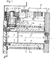
- Fig. 1 shows the tool changer, which is received in a known manner in a stand 10 of a machine tool (not shown) and which has a hollow base body 5 rotatably and axially displaceably mounted on the cylindrical outer surface of the bearing body 4, at the front end of which a gripper device 6 is fastened by six screws 7.
- the longitudinal axis of the base body 5 is parallel to the axis of the spindle of the machine tool and the axis of the magazine holder in the tool change position (not shown).
- the gripper device 6 is designed in a known manner, not shown, as a double gripper which can be actuated by a device, not shown, in the bearing body 4.
- the base body 5 has a cylindrical outer surface and has a guide bore 8 which is coaxial in the direction of its cylinder axis and which is provided for receiving the bearing body 4, the rear end of which is connected to the stand 10 by four screws 9 on a front stop surface of the stand 10, so that the cylinder axis of the base body 5 forms its axis of rotation 13.
- the guide bore 8 has an extension 11 which extends over approximately three quarters of its length and in which a plain bearing bushing 12 for pressing the base body 5 onto the bearing body 4 is pressed.
- a bore 14 running parallel to the axis of rotation 13, the rear end of which is connected to a lubricant feed line 15 in the stator 10.
- the front end of the bore 14 is connected to an annular lubrication groove 16 in the outer surface of the bearing body 4.
- the lubrication groove 16 is arranged at such a distance from the stop surface of the stator 10 that it always supplies the slide bearing bush 12 with lubricant during the axial displacement of the base body 5.
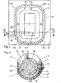
- a U-shaped rack 17 is provided, which has a leg 17a running parallel to the axis of rotation 13 in the direction from the gripper device 6 to a rear deflection 18a, which deflects there by 90 ° into the web 17b of the rack 17 , which extends in a plane perpendicular to the axis of rotation 13 in a circular arc by 180 "around the longitudinal axis 13 until it deflects in a further deflection 18b by 90 ° into the second leg 17c, which runs from the rear deflection 18b parallel to the axis of rotation 13 in the direction extends to the gripper device 6 (see FIG. 2)
- This rack 17 is formed on one side wall of a groove 20.
- the groove 20 is not limited on the sides opposite the rack legs 17a and 17c, so that there is a flat base 21 there there is an aligned edge 25 of the groove 20.
- a groove 22 (FIG. 3) parallel to the rack 20 is inserted, the bottom 23 of which is parallel to the base 21 Groove 20 is.
- a pinion 26 which is designed as the lower part of a shaft 27, whose longitudinal axis is parallel to the side walls 24 of the groove 22, engages in the toothed rack 17.
- a cam roller 31 which is guided in the groove 23, the diameter of the cam roller 31 corresponding to the clear width between the two side walls 24 of the groove 22.
- a V-belt pulley 32a is connected to the upper part of the shaft 27 via a key 33. Between the V-belt pulley 32a and the pinion 26, the shaft 27 is rotatably mounted in a bush 35 via two ball bearings 34. The ball bearings 34 are held apart by a spacer bush 36 so that the two bearings come into contact with one surface of the V-belt pulley 32a and the pinion 26, respectively.
- the bush 35 is fastened by screws 37 in a cylindrical recess 38 at the front end of a plate 39, which is welded to the front stop surface of the stand 10 above the base body 5 with its rear end.
- the V-belt pulley 32a and thus the shaft 27 with the pinion 26 can be driven via two narrow V-belts 41 by a second V-belt pulley 32b, which sits on an output shaft of a motor 47.
- the motor 47 is mounted in a manner not shown in Fig.1 from left to right in the stator 10.
- a web 42 is provided for a V-belt tensioning screw 44 which engages the motor 47.
- a tool located in the spindle is exchanged for a tool from the tool magazine.
- a drum magazine (not shown) can be used as the tool magazine, in which the tools are accommodated in quivers in a known manner.
- the tool in the holder is identified in a known manner by means of a control via a code and brought into the tool changing position by rotating the drum magazine and possibly with subsequent pivoting of the holder in such a way that the tool can be removed from the holder by a gripper of the double gripper.
- the axis of the tool to be replaced in the spindle and the axis of the tool in the holder are parallel to the axis of rotation 13 of the base body.
- the opened gripping pliers which are assigned to the tool in the spindle and which always remain in the gripping area of this tool even during machining, and the opened gripping groove, into which the tool has been pivoted into the holder, are closed.
- the actual tool changing process begins when the control switches on the motor 47 of the tool changer after the two gripping tongs have been closed.
- the V-belt pulley 32b drives the V-belt pulley 32a and thus the shaft 27 with the pinion 26 in a direction of rotation in which the base body is moved axially forward (to the left in FIG. 1).
- the double gripper with its two closed gripping tongs pulls the tools to be replaced out of the spindle and the magazine holder at the same time.
- the control releases the gripping tongs so that the machining can be started with the tool in the spindle, while the exchanged tool is pivoted back into its original position in the magazine holder.
- the shaft 27 is guided with the pinion 26 in the groove 22 of the groove 20. Since after this tool change process the base body 5 is pivoted by 180 ° with the toothed rack 17, that is to say opposite to the position as shown in FIG. 1, the motor must be switched in the direction of rotation for the next tool change.
- the motor 47 can be provided with a gear which converts the uniform rotary movement of the motor shaft into a non-uniform movement of the V-belt pulley 32b, e.g. an oval gear transmission (not shown).
- a gear which converts the uniform rotary movement of the motor shaft into a non-uniform movement of the V-belt pulley 32b e.g. an oval gear transmission (not shown).
- the gear ratio can be changed during a tool change in such a way that the axial and rotary movements of the base body 5 are rapid and the throughput speeds in the deflections 18a, 18b are slow.
- the motor 47 can be controllable with regard to the speed and the direction of rotation.
- the load can be lifted by the tools to be replaced can be measured via a sensor located in the bearing body 4.
- the sensor system influences the control in such a way that the output speed of the motor 47 is throttled when changing particularly heavy tools, so that the entire tool changing process can be carried out more slowly and thus overstressing the tool changer is avoided.
- the axially parallel rack legs 17a and 17c are shorter than in the embodiment according to FIGS. 1 to 3, so that when the base body 5 is in its rear position, the pinion 26 has emerged from the corresponding leg 17a or 17c of the U-shaped rack 17 of the base body 5. Since the base body 5 is thereby no longer held in the defined rotational position by the cam roller 31 engaging in the groove 22, a locking of the base body 5 with the bearing body 4 is provided for this purpose.
- This lock consists of a pin 51, which is fastened to the gripper device 6 and is arranged coaxially with the axis of rotation of the base body 5 and which carries an axially extending and radially projecting strip 52.
- the bearing body 4 In the front end of the bearing body 4 there is also a bore which is coaxial with the axis of rotation 13 of the base body 5 for the engagement of the pin 51 and which has a groove 50 in its cylindrical wall for the engagement of the strip 52, so that the base body is axially displaced 5 from its front position to its rear position before the cam roller 31 emerges from the groove 22 of the pin 51 into the front bore of the bearing body 4 and thus the bar 52 engages in the groove 50 provided in this bore and the gripper device 6 and thus the base body 5 is locked to the bearing body 4 by this tongue and groove lock 50, 52.
- the base body 5 is tapered to a radius that is smaller than the distance of the groove bottom 23 from the axis of rotation 13. This shortens the two axial legs 17a and 17c of the rack 17.
- a ring 53 is rotatably mounted on the tapered end of the base body 5, which takes up this entire space.
- This toothed rack 54 is also formed within a groove in the ring 53, like the toothed rack 17 in the base body 5, and has a guide groove 56 which continues the groove 22 in a basic position of the ring 53 and corresponds to the groove 22 in the groove base. In this basic position, the rack 54 continues the rack 17, so that a closed rack ring for the pinion 26 is formed.
- the web 54b of the U-shaped rack 54 is arranged so that when the cam roller 31 of the pinion 26 engages in the web of the U-shaped groove 56 running along the rack web 54b, the base body 5 in the rear position, namely in the end position of the tool changing process.
- a catch is provided which is formed by a spring-loaded ball 57 which engages in an axially extending groove 58 of the base body 5 .
- the drive 53 for the closing and opening of the grippers is provided with the ring 53, which is connected to the grippers via a cam mechanism, not shown, with detent positions and a control system, likewise not shown, which is designed accordingly.
- the pinion 26 rotates in a direction opposite to the previous direction of rotation, so that the ring 53 rotates until the pinion meshes with one of the deflections 55a or 55b and the ring thus assumes its basic position relative to the base body 5.
- This rotation closes the grippers so that the tools to be changed are gripped by the grippers.
- the base body is moved axially forward and the tool change takes place as in the previously described embodiment, only that at the end of the return stroke of the base body 5 the pinion meshes again with the rack web 54b and rotates the ring 53, whereby the grippers be opened.
- the control which connects the drive member 59 to the grippers always reverses the action of the drive member 59 on the grippers, thus the grippers always at the beginning of a tool change closed and the grippers opened at the end of the tool change.
- a cam mechanism with locking positions can expediently be used in the connection between the drive member 59 and the grippers. As a result, it is only necessary for the ring to make a minimum rotation for actuating the grippers, but its movement is not restricted to this minimum rotation, so that the drive motor 47 of the pinion 26 does not have to be stopped at a precisely defined position of the ring 53.
Landscapes
- Engineering & Computer Science (AREA)
- Mechanical Engineering (AREA)
- General Engineering & Computer Science (AREA)
- Automatic Tool Replacement In Machine Tools (AREA)
Applications Claiming Priority (4)
| Application Number | Priority Date | Filing Date | Title |
|---|---|---|---|
| DE3522156 | 1985-06-21 | ||
| DE3522156 | 1985-06-21 | ||
| DE3536048 | 1985-10-09 | ||
| DE19853536048 DE3536048A1 (de) | 1985-06-21 | 1985-10-09 | Werkzeugwechsler |
Publications (3)
| Publication Number | Publication Date |
|---|---|
| EP0209619A2 true EP0209619A2 (fr) | 1987-01-28 |
| EP0209619A3 EP0209619A3 (en) | 1988-08-10 |
| EP0209619B1 EP0209619B1 (fr) | 1990-12-27 |
Family
ID=25833301
Family Applications (1)
| Application Number | Title | Priority Date | Filing Date |
|---|---|---|---|
| EP85113109A Expired - Lifetime EP0209619B1 (fr) | 1985-06-21 | 1985-10-16 | Changeur d'outil |
Country Status (3)
| Country | Link |
|---|---|
| US (1) | US4727642A (fr) |
| EP (1) | EP0209619B1 (fr) |
| DE (2) | DE3536048A1 (fr) |
Families Citing this family (5)
| Publication number | Priority date | Publication date | Assignee | Title |
|---|---|---|---|---|
| US5498053A (en) * | 1994-03-25 | 1996-03-12 | Jay Roberts Company | Reciprocating plate mechanism |
| US7007331B2 (en) * | 2003-11-05 | 2006-03-07 | The Procter & Gamble Company | Electric toothbrushes having a moving viewing surface |
| DE102008025076B4 (de) * | 2008-05-26 | 2015-12-03 | Iht Automation Gmbh & Co. Kg | Antriebsvorrichtung |
| US9205508B2 (en) | 2011-11-18 | 2015-12-08 | Lincoln Global, Inc. | Tractor unit drive gear engagement device |
| USD1118727S1 (en) * | 2024-02-23 | 2026-03-17 | Sanjet International Co., Ltd. | Vertical-horizontal tool changer mechanism |
Family Cites Families (11)
| Publication number | Priority date | Publication date | Assignee | Title |
|---|---|---|---|---|
| US1099874A (en) * | 1912-07-12 | 1914-06-09 | John G Dorward | Pump-head-reciprocating mechanism. |
| US1440035A (en) * | 1922-03-01 | 1922-12-26 | James F Struble | Windmill gearing |
| US1534789A (en) * | 1924-04-24 | 1925-04-21 | Judelson Louis | Gear |
| FR948436A (fr) * | 1947-06-10 | 1949-08-01 | Transformation de mouvement, rotatif en rectiligne alterné et vice versa, par un nouveau procédé de conversion de crémaillères | |
| US3218706A (en) * | 1962-08-30 | 1965-11-23 | Kearney & Trecker Corp | Machine tool with tool changer |
| SU255746A1 (ru) * | 1967-04-22 | 1970-04-10 | Манипулятор | |
| DE2331630A1 (de) * | 1973-06-22 | 1975-01-23 | Ludwigsburger Masch Bau | Werkzeugmaschine mit werkzeugmagazin und werkzeugwechsler |
| SU755496A1 (ru) * | 1978-05-25 | 1980-08-15 | Viktor A Ukholov | Устройство для автоматической смены инструментов 1 |
| JPS57211443A (en) * | 1981-06-18 | 1982-12-25 | Toyoda Mach Works Ltd | Automatic tool replacing device |
| JPS5845837A (ja) * | 1981-09-14 | 1983-03-17 | Okuma Mach Works Ltd | 自動工具交換方法及び装置 |
| US4432692A (en) * | 1981-10-28 | 1984-02-21 | Woodford Manufacturing Company | Article handling apparatus |
-
1985
- 1985-10-09 DE DE19853536048 patent/DE3536048A1/de not_active Withdrawn
- 1985-10-16 EP EP85113109A patent/EP0209619B1/fr not_active Expired - Lifetime
- 1985-10-16 DE DE8585113109T patent/DE3581208D1/de not_active Expired - Fee Related
-
1986
- 1986-05-20 US US06/864,838 patent/US4727642A/en not_active Expired - Fee Related
Also Published As
| Publication number | Publication date |
|---|---|
| US4727642A (en) | 1988-03-01 |
| EP0209619A3 (en) | 1988-08-10 |
| EP0209619B1 (fr) | 1990-12-27 |
| DE3536048A1 (de) | 1987-01-02 |
| DE3581208D1 (de) | 1991-02-07 |
Similar Documents
| Publication | Publication Date | Title |
|---|---|---|
| EP1224048B1 (fr) | Porte-outil | |
| EP1982799B1 (fr) | Agencement de manipulation | |
| DE2523460A1 (de) | Gewindeschneidwerkzeug | |
| DE3017613C2 (fr) | ||
| DE1602810C3 (de) | Drehmaschine mit einer Werkzeugwechselvorrichtung | |
| EP0949021B1 (fr) | Dispositif pour le formage de fil ayant un dispositif de freinage de fil | |
| DE2401064A1 (de) | Selbsttaetig arbeitende werkstoffstangen-vorschubeinrichtung fuer mehrspindeldrehautomaten, insbesondere fuer mehrspindellangdrehautomaten | |
| DE3519754C2 (fr) | ||
| EP0209619B1 (fr) | Changeur d'outil | |
| DE2335605B2 (de) | Zu- und Abführeinrichtung für Werkstücke eines Mehrspindeldrehautomaten | |
| DE3503637A1 (de) | Werkzeugmaschine fuer die spanabhebende bearbeitung von werkstuecken mit verschiedenen werkzeugen | |
| CH636030A5 (de) | Stangenfoermigen werkstoff verarbeitender drehautomat. | |
| DE2207045C3 (de) | Vorrichtung zum Gewindeschneiden | |
| DE2544074C2 (de) | Vorrichtung an einem Mehrspindeldrehautomaten zum Einfräsen von Schlitzen in Werkstücke | |
| DE3634364C2 (fr) | ||
| DE1477278A1 (de) | Vorschubeinrichtung fuer Automatendrehbaenke | |
| DE616771C (de) | Kegeldrehvorrichtung fuer den Querschlitten selbsttaetiger Drehbaenke | |
| DE1602943C (de) | Drehautomat mit Mehrspindelapparat | |
| DE2332173A1 (de) | Transfer-werkzeugmaschine mit mehreren drehbaren spannfuttern fuer die werkstuecke | |
| DE8518008U1 (de) | Werkzeugwechsler | |
| DE29923695U1 (de) | Werkzeughalter | |
| DE2932599A1 (de) | Werkstueckaufnahmevorrichtung fuer eine werkzeugmaschine | |
| DE2025460C3 (de) | Kurvengesteuerter Langdrehautomat | |
| DD239751B1 (de) | Vorrichtung zum begrenzen des oeffnungsweges der greiforgane eines backengreifers | |
| DE1602811C3 (de) | Werkzeugwechselvorrichtung für Werkzeugmaschinen mit Werkzeugmagazinen |
Legal Events
| Date | Code | Title | Description |
|---|---|---|---|
| PUAI | Public reference made under article 153(3) epc to a published international application that has entered the european phase |
Free format text: ORIGINAL CODE: 0009012 |
|
| AK | Designated contracting states |
Kind code of ref document: A2 Designated state(s): DE FR GB IT |
|
| PUAL | Search report despatched |
Free format text: ORIGINAL CODE: 0009013 |
|
| AK | Designated contracting states |
Kind code of ref document: A3 Designated state(s): DE FR GB IT |
|
| 17P | Request for examination filed |
Effective date: 19880718 |
|
| 17Q | First examination report despatched |
Effective date: 19890503 |
|
| RAP1 | Party data changed (applicant data changed or rights of an application transferred) |
Owner name: BURKHARDT + WEBER GMBH |
|
| GRAA | (expected) grant |
Free format text: ORIGINAL CODE: 0009210 |
|
| AK | Designated contracting states |
Kind code of ref document: B1 Designated state(s): DE FR GB IT |
|
| REF | Corresponds to: |
Ref document number: 3581208 Country of ref document: DE Date of ref document: 19910207 |
|
| GBT | Gb: translation of ep patent filed (gb section 77(6)(a)/1977) | ||
| ET | Fr: translation filed | ||
| ITF | It: translation for a ep patent filed | ||
| ITTA | It: last paid annual fee | ||
| PLBE | No opposition filed within time limit |
Free format text: ORIGINAL CODE: 0009261 |
|
| STAA | Information on the status of an ep patent application or granted ep patent |
Free format text: STATUS: NO OPPOSITION FILED WITHIN TIME LIMIT |
|
| 26N | No opposition filed | ||
| PGFP | Annual fee paid to national office [announced via postgrant information from national office to epo] |
Ref country code: GB Payment date: 19930921 Year of fee payment: 9 |
|
| PGFP | Annual fee paid to national office [announced via postgrant information from national office to epo] |
Ref country code: FR Payment date: 19931022 Year of fee payment: 9 |
|
| PGFP | Annual fee paid to national office [announced via postgrant information from national office to epo] |
Ref country code: DE Payment date: 19931119 Year of fee payment: 9 |
|
| PG25 | Lapsed in a contracting state [announced via postgrant information from national office to epo] |
Ref country code: GB Effective date: 19941016 |
|
| GBPC | Gb: european patent ceased through non-payment of renewal fee |
Effective date: 19941016 |
|
| PG25 | Lapsed in a contracting state [announced via postgrant information from national office to epo] |
Ref country code: FR Effective date: 19950630 |
|
| PG25 | Lapsed in a contracting state [announced via postgrant information from national office to epo] |
Ref country code: DE Effective date: 19950701 |
|
| REG | Reference to a national code |
Ref country code: FR Ref legal event code: ST |