EP0209901A2 - Dispositif d'aspiration de saleté - Google Patents
Dispositif d'aspiration de saleté Download PDFInfo
- Publication number
- EP0209901A2 EP0209901A2 EP86110135A EP86110135A EP0209901A2 EP 0209901 A2 EP0209901 A2 EP 0209901A2 EP 86110135 A EP86110135 A EP 86110135A EP 86110135 A EP86110135 A EP 86110135A EP 0209901 A2 EP0209901 A2 EP 0209901A2
- Authority
- EP
- European Patent Office
- Prior art keywords
- suction
- dirt
- suction box
- auxiliary
- main
- Prior art date
- Legal status (The legal status is an assumption and is not a legal conclusion. Google has not performed a legal analysis and makes no representation as to the accuracy of the status listed.)
- Ceased
Links
Images

Classifications
-
- A—HUMAN NECESSITIES
- A47—FURNITURE; DOMESTIC ARTICLES OR APPLIANCES; COFFEE MILLS; SPICE MILLS; SUCTION CLEANERS IN GENERAL
- A47L—DOMESTIC WASHING OR CLEANING; SUCTION CLEANERS IN GENERAL
- A47L9/00—Details or accessories of suction cleaners, e.g. mechanical means for controlling the suction or for effecting pulsating action; Storing devices specially adapted to suction cleaners or parts thereof; Carrying-vehicles specially adapted for suction cleaners
- A47L9/28—Installation of the electric equipment, e.g. adaptation or attachment to the suction cleaner; Controlling suction cleaners by electric means
- A47L9/2857—User input or output elements for control, e.g. buttons, switches or displays
-
- A—HUMAN NECESSITIES
- A47—FURNITURE; DOMESTIC ARTICLES OR APPLIANCES; COFFEE MILLS; SPICE MILLS; SUCTION CLEANERS IN GENERAL
- A47L—DOMESTIC WASHING OR CLEANING; SUCTION CLEANERS IN GENERAL
- A47L5/00—Structural features of suction cleaners
- A47L5/12—Structural features of suction cleaners with power-driven air-pumps or air-compressors, e.g. driven by motor vehicle engine vacuum
- A47L5/22—Structural features of suction cleaners with power-driven air-pumps or air-compressors, e.g. driven by motor vehicle engine vacuum with rotary fans
- A47L5/38—Built-in suction cleaner installations, i.e. with fixed tube system to which, at different stations, hoses can be connected
-
- A—HUMAN NECESSITIES
- A47—FURNITURE; DOMESTIC ARTICLES OR APPLIANCES; COFFEE MILLS; SPICE MILLS; SUCTION CLEANERS IN GENERAL
- A47L—DOMESTIC WASHING OR CLEANING; SUCTION CLEANERS IN GENERAL
- A47L9/00—Details or accessories of suction cleaners, e.g. mechanical means for controlling the suction or for effecting pulsating action; Storing devices specially adapted to suction cleaners or parts thereof; Carrying-vehicles specially adapted for suction cleaners
- A47L9/0009—Storing devices ; Supports, stands or holders
- A47L9/0018—Storing devices ; Supports, stands or holders integrated in or removably mounted upon the suction cleaner for storing parts of said suction cleaner
- A47L9/0036—Storing devices ; Supports, stands or holders integrated in or removably mounted upon the suction cleaner for storing parts of said suction cleaner specially adapted for holding the suction hose
-
- A—HUMAN NECESSITIES
- A47—FURNITURE; DOMESTIC ARTICLES OR APPLIANCES; COFFEE MILLS; SPICE MILLS; SUCTION CLEANERS IN GENERAL
- A47L—DOMESTIC WASHING OR CLEANING; SUCTION CLEANERS IN GENERAL
- A47L9/00—Details or accessories of suction cleaners, e.g. mechanical means for controlling the suction or for effecting pulsating action; Storing devices specially adapted to suction cleaners or parts thereof; Carrying-vehicles specially adapted for suction cleaners
- A47L9/24—Hoses or pipes; Hose or pipe couplings
-
- A—HUMAN NECESSITIES
- A47—FURNITURE; DOMESTIC ARTICLES OR APPLIANCES; COFFEE MILLS; SPICE MILLS; SUCTION CLEANERS IN GENERAL
- A47L—DOMESTIC WASHING OR CLEANING; SUCTION CLEANERS IN GENERAL
- A47L9/00—Details or accessories of suction cleaners, e.g. mechanical means for controlling the suction or for effecting pulsating action; Storing devices specially adapted to suction cleaners or parts thereof; Carrying-vehicles specially adapted for suction cleaners
- A47L9/28—Installation of the electric equipment, e.g. adaptation or attachment to the suction cleaner; Controlling suction cleaners by electric means
- A47L9/2836—Installation of the electric equipment, e.g. adaptation or attachment to the suction cleaner; Controlling suction cleaners by electric means characterised by the parts which are controlled
- A47L9/2842—Suction motors or blowers
Definitions
- the invention relates to a dirt suction device with a main suction box, in which by means of at least one main vacuum source that can be switched on and off, a negative pressure can be generated for suctioning dirt through a suction channel that is led out of the suction box, a preferably flexible hose being tightly connected to the outer end of the suction channel is, which is accommodated in at least one loop in a storage box, from which it is guided to the outside through an opening, the edge of which surrounds the outer jacket of the hose.
- Such dirt suction devices are often installed at self-service petrol stations to give vehicle owners the opportunity to clean their vehicle from the inside by means of the flexible hose by guiding the suction pipe of the flexible hose over the floor and the seats of the vehicle. With such dirt suction devices, it is important that the flexible hose is stowed in the non-use position inside the housing of the device or outside at a suitable point in such a way that it is neither in the way nor can it be contaminated.
- a dirt suction device with a main suction box is already known, from which a pipe sucking the dirt is guided into a storage box in which the hose is accommodated to form a loop. From an opening in the front wall of the storage box, the hose provided with an intake socket can be pulled out of the storage box to a desired length. After use, the hose is then pushed back through the opening into the storage box (US Pat. No. 20 51 728).
- the aim of the invention is to provide a dirt suction device of the type mentioned at the beginning, with which the flexible hose is automatically drawn into a space that is completely protected from the outside after use, but at the same time automatic cleaning of the hose areas entering the housing of the device takes place.
- the invention provides that the edge surrounds the outer jacket of the hose with little play and the storage box is designed as an auxiliary suction box in which such a vacuum can be generated that the hose can be pulled out of the opening while reducing the loop against the vacuum and can be pulled into the auxiliary suction box by releasing the vacuum by enlarging the loop.
- the flexible hose insofar as its end piece does not constantly protrude from the device, is stowed in a housing which is tightly sealed on all sides and into which it is automatically sucked in by negative pressure, the being due to the negative pressure in the region of the annular gap
- High-speed suction air on the outer jacket of the flexible hose blows away any dirt or moisture present in this area. Dirt and moisture then collect on the bottom of the auxiliary suction box, from where they can be removed from time to time through a suitable door or flap. Since all areas of the outer casing of the hose must pass through the opening when the flexible hose is sucked into the auxiliary suction box, the hose along its entire outer casing is completely cleaned once in a pulling-in process.
- a stop flange is expediently provided on the hose, which limits the size of the loop.
- a certain piece of hose required for gripping still protrudes from the front wall of the dirt suction device, but it is so short that it cannot come into contact with the ground.
- this piece of hose can also be arranged completely sunk in the auxiliary suction box, so that only the end connector of the flexible hose required for suction protrudes from the front wall of the housing of the dirt suction device according to the invention.
- a signal transmitter is provided on the hose in the region of the flange, which is connected to the opening on the auxiliary suction box interacts with the signal receiver, which is connected via a line to an electrical control circuit by means of which the vacuum in the auxiliary suction box is switched off when the signal transmitter is close to the signal receiver, or is switched on when the signal transmitter is away from the signal receiver.
- the hose In order to make the compressive force acting on the hose when pulling in as large as possible at a given negative pressure inside the auxiliary suction box, the hose should have radially protruding circumferential ribs at small longitudinal intervals, the longitudinal spacings of the circumferential ribs expediently being smaller than the axial length of the opening. In this way, ring surfaces are created in the area of the opening which are essentially perpendicular to the hose axis and on which the differential pressure between the atmosphere and the interior of the auxiliary suction box can act in the sense that the flexible hose is driven into the interior of the auxiliary suction box.
- the vacuum in the auxiliary suction box can be generated by an auxiliary vacuum source.
- the vacuum in the auxiliary suction box can be generated by the main vacuum source by switching off the vacuum from the main suction box and applying it to the auxiliary suction box by means of a valve arrangement. So here are the main suction turbines intended for dirt removal at the same time used for pulling in the flexible hose by means of negative pressure.
- An advantageous practical embodiment is characterized in that a preferably vertical partition is provided between the main suction box and the auxiliary suction box, in which the suction box opens preferably at a medium height.
- a further expedient embodiment is designed such that a preferably horizontal transverse wall is arranged above the main suction box, in which at least one main suction turbine is arranged as the main negative pressure source.
- control circuit and other actuating elements are arranged above the transverse wall.
- a further development of the invention which is essential for a compact arrangement, is characterized in that an auxiliary suction turbine is arranged as an auxiliary vacuum source above the transverse wall in the intermediate wall.
- the invention also seeks to remedy this situation by ensuring that most of the dirt sucked falls into the dirt-collecting container and only as little dirt or dust as possible reaches the filters, which should be as large as possible.
- the invention provides for a dirt suction device according to the preamble of claim 1 that below the main suction turbine (s) with a vertical distance, a horizontally extending baffle plate extending all around beyond the suction openings is provided, below which an open top Dirt collecting container is arranged, into which the intake duct opens from above.
- ring filter packets should be arranged tightly between the transverse wall containing the main suction turbine (s) and the baffle plate.
- the ring filter packs lie with their upper and lower edges close to the transverse wall or the baffle plate.
- the ring filter packs should be essentially rectangular or round.
- each ring filter package consists of filter material folded like an accordion and / or provided with folded filter bags.
- the exit velocity of the dirt-air flow within the dirt-collecting container is relatively high, but due to the comparatively large diameter of the dirt-collecting container, there is a sudden expansion that leads upwards out of the dirt-collecting container escaping air flow considerably and suddenly slowed down so that only a little dirt is carried upwards.
- the baffle plate hits the baffle plate from below and is thus thrown back in the direction of the dirt collecting container.
- the air is deflected at the baffle plate and enters laterally around it into the wall-shaped filter, where there has already been extensive separation of dirt and air.
- the relatively large filter area effectively prevents the filter from clogging quickly due to entrained dust.
- Such dirt suction devices in self-service filling stations are generally triggered by the insertion of a coin.
- the control circuit first starts the main suction turbines for a certain period of time.
- the operator can now pull the hose out of the vacuum suction box and carry out the desired cleaning work.
- the main suction turbines switch off, and at the same time the auxiliary suction turbine is switched on. If the user now releases the hose, it is automatically drawn into the auxiliary suction box, the loop being formed and dirt being removed from the jacket of the hose.
- the suction of the hose then continues until the flange provided on it abuts against the front wall of the housing next to the suction opening, whereupon the signal generator, in cooperation with the signal receiver, switches off the auxiliary suction turbine via the control circuit.
- a preferred embodiment of the invention thus consists in that the control circuit switches off the negative pressure in the auxiliary suction box when the main suction turbines are switched on and switches on the negative pressure in the auxiliary suction box when the main suction turbines are switched off, provided that the signal generator and the signal receiver are separated from one another.
- a preferred practical embodiment is characterized in that the auxiliary suction box extends alongside the main suction box and the receiving space above it over the entire height of the device.
- the hose can be placed in a simple loop inside the vacuum box. In principle, however, it is also possible to form the loop by rolling up the hose, provided that longer, extendable hose lengths are desired.
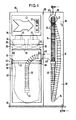
- the dirt suction device according to the invention is accommodated in a cuboid sheet metal or plastic housing 36, which is at the bottom on the floor 37 of a self-service filling station.
- the front wall 38 of the housing 36 has, in its left area in FIG. 1, a removable rectangular flap 39 which is slightly higher than half the height of the housing 36 and whose width is slightly larger than the width of the housing 36. 1 to 3, at about half the height of the housing 36, there is a holding device 40 for a sack-like dirt collecting container 32 on the left side wall 41 in FIG. 1 and on a vertical intermediate wall 29 of the housing 36 intended.
- a clamping frame 42 which holds the dirt collecting container 32 at the top engages in the holding device 40.
- a wall outlet 43 to which a downwardly curved suction hose 13 connects to the dirt collecting container 32, the outlet end 44 of which opens as far down as possible within the dirt collecting container 32.
- a horizontally extending flat baffle plate 31 is fastened in a manner not shown, in addition to which air passage gaps 44 are provided all around.
- a transverse wall 30 extending transversely between the intermediate wall 29 and the side wall 41, which divides the housing 36 into a lower main suction box 11 and an upper receiving space 35 for various actuation and drive elements.
- Two main suction turbines 12 are installed side by side in the transverse wall 30, the suction openings (not shown) of which are surrounded by ring filter packs 33 which consist of filter material folded in the manner shown.
- the ring filter packs 33 lie close to the transverse wall 30 from below and there surround the suction opening of the main suction turbine 12, not shown.
- the ring filter packs 33 lie close to the top of the baffle plate 31 below.
- the air sucked in by the main suction turbines 12 is thus forced to strike the large, wrinkled outer wall 34 of the ring filter package 34 through the wide annular gaps 44.
- the filtered air is then blown out by the main suction turbines 12 in a manner not shown.
- the intake duct 13 which is preferably also designed as a flexible hose, merges into a flexible hose 14 following the feed-through connector 43 and a pipe elbow 45 which is angled downward by 90 ° down and then finally up to a circular passage opening 17 provided in the front wall of the housing 36, where it passes through the front wall from the inside to the outside, and then vertically in the manner shown in FIGS. 1 and 2 hanging down below.
- a suction port 46 is attached at the outer end of the flexible hose 14.
- the flexible hose is provided with circumferential ribs 24 all around at relatively short longitudinal distances.
- the flexible hose 14 has a stop flange 19 all around, which continues in the direction of the loop 15 into a shrink tube piece 46, within which a signal transmitter 20 which is as flat as possible is accommodated, e.g. can be designed as a magnetic or metal plate.
- the material 47 around the opening 17 has a certain extent in the axial direction, which should be greater than the longitudinal spacing of the circumferential ribs 24.
- the dimensioning of the diameter of the opening 17 is selected so that a slight play remains between the circumferential ribs or the shrink tube 46 and the edge 18 of the opening 17.
- the area of the housing 36 on the left in FIG. 7 forms an auxiliary suction box 16 which is continuous from top to bottom and is airtight on all sides except for the opening 17 and which can be placed under negative pressure by an auxiliary suction turbine 25 connected to the intermediate wall 29 at the top right in FIG. 2 .
- the auxiliary suction turbine 25 is connected to the auxiliary suction box 16 through a bore 48.
- a signal receiver 21 which as a switch responding to a metal plate or a magnetic plate, e.g. Reed switch can be formed.
- the signal receiver 21 is connected via a line 22 to a control circuit 23 which is accommodated in the receiving space 35 above the main suction turbines 12.
- the control circuit 23 also switches the main suction turbines 12 and the auxiliary suction turbine 25.
- a further embodiment is also indicated in dash-dotted lines in FIG. 3, in which the main suction turbines 12 are also used to generate the negative pressure in the auxiliary suction box 16, as a result of which the auxiliary suction turbine 25 can be dispensed with.
- a perforated plate 27 can be arranged below the baffle plate 31, which extends over the entire horizontal cross-sectional area of the main suction box 11.
- a perforated slide valve 26 which in the position shown is air passage from bottom to top possible.
- the slide valve 26 is moved by an actuating device 49 in the direction of arrow f in FIG. 3, the holes in the perforated plate 27 and the slide valve 26 become out of alignment, which leads to an airtight seal between the auxiliary suction box 11 and the space above the slide valve 26 leads.
- control circuit 23 excites a further actuating device 50, which opens a flap 28 provided in the intermediate wall 29 and thus establishes a flow connection between the main suction turbines 12 and the auxiliary suction box 16.
- the control circuit 23 controls the flap 28 on the one hand and the hole slide 26 on the other hand such that the main suction turbines 12 are connected either to the main suction box 11 or to the auxiliary suction box 16.
- control circuit 23 switches off the main suction turbines 12 and at the same time switches on the auxiliary suction turbine 25.
- the slide gate 26 are switched into the closing and the flap 28 into the open position, in which case the main suction turbines 12 would continue to run.
- a foam body 53 provided with deep grooves is preferably provided on the base 52, the grooves being so narrow and deep that dust and dirt stripped from the tube 14 can collect therein, but the tube 14 resting on the base 52 does not come into contact with the dust collected in the grooves again, which could otherwise lead to re-contamination. In this way, the flexible hose 14 with the lower sagging loop 15 can rest on the floor 52.
- the flexible hose 14 is sucked in until the flange 19 comes into contact with the front wall of the housing.
- the signal generator 20 switches off the auxiliary suction turbine 25 and the main suction turbine 12 via the signal generator 21 and the control circuit 23.
- auxiliary turbine 25 In the area of the intake opening 48 of the auxiliary turbine 25 there is a prefilter, not shown.
- the pressure generated by the auxiliary turbine 25 is 140 mm WS.
- the signal transmitter 20 and signal receiver 21 can expediently be an inductive proximity switch.
- the can 18 surrounding the inlet opening 17 is expediently designed as a Teflon nozzle.
- the hose 14 is guided through the passage opening 17 with as little play as possible, but the play is dimensioned sufficiently large so that the flexible hose 14 does not get caught in the opening 17 when it is sucked in or pulled out.
- the outlet opening 17 should be provided as far as possible at the top in the front wall of the housing 36, while the transition piece 43 for the connection of the intake duct 13 is arranged at the very front and as high as possible on the intermediate wall 29.
- the intake duct 13 opens directly above the holding device 40 for the dirt collecting container 32.
- the elbow 45 can be pivotable about the horizontal axis 54 common to the connecting piece 43.
- the tube has only a single loop 15 in the drawn-in state from its entry end to its exit end, thereby ensuring that it is drawn in easily.
- the auxiliary suction turbine 25 is expediently switched only by the switching device 20, 21, so that it always runs when the hose is pulled out, i.e. even when the main suction turbine 12 is switched on. Then the extension length can always be automatically adapted to the requirements.
Landscapes
- Engineering & Computer Science (AREA)
- Mechanical Engineering (AREA)
- Cleaning In General (AREA)
- Nozzles For Electric Vacuum Cleaners (AREA)
Applications Claiming Priority (2)
| Application Number | Priority Date | Filing Date | Title |
|---|---|---|---|
| DE19853526328 DE3526328A1 (de) | 1985-07-23 | 1985-07-23 | Schmutzsaugvorrichtung |
| DE3526328 | 1985-07-23 |
Publications (2)
| Publication Number | Publication Date |
|---|---|
| EP0209901A2 true EP0209901A2 (fr) | 1987-01-28 |
| EP0209901A3 EP0209901A3 (fr) | 1988-01-20 |
Family
ID=6276527
Family Applications (1)
| Application Number | Title | Priority Date | Filing Date |
|---|---|---|---|
| EP86110135A Ceased EP0209901A3 (fr) | 1985-07-23 | 1986-07-23 | Dispositif d'aspiration de saleté |
Country Status (3)
| Country | Link |
|---|---|
| US (1) | US4688292A (fr) |
| EP (1) | EP0209901A3 (fr) |
| DE (1) | DE3526328A1 (fr) |
Cited By (1)
| Publication number | Priority date | Publication date | Assignee | Title |
|---|---|---|---|---|
| US5651945A (en) * | 1994-07-30 | 1997-07-29 | Degussa Aktiengesellschaft | Carbon black reactor and method of producing carbon black |
Families Citing this family (25)
| Publication number | Priority date | Publication date | Assignee | Title |
|---|---|---|---|---|
| DE8634311U1 (de) * | 1986-12-22 | 1987-02-26 | Rowenta-Werke Gmbh, 6050 Offenbach | Staubsauger |
| DE8903472U1 (de) * | 1989-03-20 | 1989-05-03 | Sohler Airtex GmbH, 7988 Wangen | Reinigungsvorrichtung für Textilmaschinen |
| ES2041635T3 (es) * | 1990-01-24 | 1995-09-16 | Vaccar Systems Pty Ltd | Una instalacion de plataforma de estacion de servicio. |
| CA2093715A1 (fr) * | 1993-04-08 | 1994-10-09 | Garry Workhoven | Appareil servant au rangement et a la mise en place du boyau d'un systeme d'aspirateur central |
| US5740581A (en) * | 1996-06-21 | 1998-04-21 | Vacs America, Inc. | Freestanding central vacuum system |
| US6389641B1 (en) | 1998-06-15 | 2002-05-21 | Tennant Company | Dual mode debris pickup machine |
| US6092261A (en) * | 1998-06-17 | 2000-07-25 | Tennant Company | Storage system for vacuum pickup hose |
| US6044954A (en) * | 1998-06-19 | 2000-04-04 | Western Paytel, Inc. | Method and apparatus for selective operation of an air compressor and vacuum machine |
| US6058560A (en) * | 1998-08-04 | 2000-05-09 | Gab; Wayne Gerard | Vac-in-a-box |
| DE29816382U1 (de) | 1998-09-11 | 1998-11-19 | Ewa Lufttechnik Gmbh | Luftreinigungsgerät |
| EP1031311A1 (fr) * | 1999-02-16 | 2000-08-30 | Flexible Ducting Limited | Tuyau d'aspiration comprenant des portions rigides et flexibles |
| US6427284B1 (en) | 2000-12-20 | 2002-08-06 | Vacs America, Inc. | Central vacuum hose storage |
| US6560816B1 (en) * | 2001-01-31 | 2003-05-13 | Vacs America, Inc. | Central vacuum system with bag mounting assembly |
| US7010829B2 (en) * | 2003-06-05 | 2006-03-14 | James Roger Harman | Retractable hose central vacuum cleaning system apparatus and method |
| GB2409403B (en) * | 2003-12-23 | 2006-12-27 | Techtronic Ind Co Ltd | Suction cleaners |
| US7363679B2 (en) * | 2005-07-22 | 2008-04-29 | Whirlpool Corporation | Vacuum system |
| US20070017057A1 (en) * | 2005-07-22 | 2007-01-25 | Zimmerle Johnny W | Convertible vacuum system |
| DE102006006009A1 (de) * | 2006-02-08 | 2007-08-09 | Degussa Gmbh | Verfahren zur Messung der gleichmäßigen Befüllung von Reaktoren mit Festkörpern |
| US20090188073A1 (en) * | 2008-01-29 | 2009-07-30 | H-P Products, Inc. | Vacuum hose storage system |
| US7945990B2 (en) * | 2008-01-29 | 2011-05-24 | H-P Products, Inc. | Vacuum hose storage system |
| US8590098B2 (en) * | 2008-01-29 | 2013-11-26 | H-P Products, Inc. | Vacuum hose storage system |
| US8479353B2 (en) * | 2008-07-23 | 2013-07-09 | Rod Drivstuen | Hose valve apparatus and method for retractable hose vaccum systems |
| BE1022169B1 (nl) * | 2014-11-28 | 2016-02-24 | Ergox Bvba | Centraal stofzuigsysteem en gebruik ervan |
| US10292558B2 (en) * | 2015-02-25 | 2019-05-21 | M.D. Manufacturing, Inc. | Vacuum hose retraction system |
| US11751735B2 (en) * | 2020-06-01 | 2023-09-12 | M.D. Manufacturing, Inc. | Vacuum and hose retraction system |
Family Cites Families (9)
| Publication number | Priority date | Publication date | Assignee | Title |
|---|---|---|---|---|
| US1896128A (en) * | 1931-06-08 | 1933-02-07 | Ralph C Thompson | Clothes brushing and cleaning appliance |
| US2023955A (en) * | 1933-05-09 | 1935-12-10 | Laval A Cowen | Vending machine |
| US2051728A (en) * | 1935-01-11 | 1936-08-18 | Richard H Manning | Vacuum cleaner |
| FR1236062A (fr) * | 1959-06-03 | 1960-07-15 | Dispositif d'épuration d'un corps chargé de particules étrangères | |
| JPS49135458A (fr) * | 1973-04-28 | 1974-12-26 | ||
| US3977037A (en) * | 1973-10-15 | 1976-08-31 | Sanyo Electric Co., Ltd. | Vacuum cleaner |
| JPS50150277A (fr) * | 1974-05-25 | 1975-12-02 | ||
| GB1472384A (en) * | 1975-01-24 | 1977-05-04 | Wright G | Vacuum cleaners |
| US4246675A (en) * | 1979-07-27 | 1981-01-27 | Costanzo Dean V | Industrial vacuum apparatus |
-
1985
- 1985-07-23 DE DE19853526328 patent/DE3526328A1/de active Granted
-
1986
- 1986-07-21 US US06/887,313 patent/US4688292A/en not_active Expired - Fee Related
- 1986-07-23 EP EP86110135A patent/EP0209901A3/fr not_active Ceased
Cited By (1)
| Publication number | Priority date | Publication date | Assignee | Title |
|---|---|---|---|---|
| US5651945A (en) * | 1994-07-30 | 1997-07-29 | Degussa Aktiengesellschaft | Carbon black reactor and method of producing carbon black |
Also Published As
| Publication number | Publication date |
|---|---|
| US4688292A (en) | 1987-08-25 |
| EP0209901A3 (fr) | 1988-01-20 |
| DE3526328C2 (fr) | 1987-11-26 |
| DE3526328A1 (de) | 1987-02-05 |
Similar Documents
| Publication | Publication Date | Title |
|---|---|---|
| DE3526328C2 (fr) | ||
| DE4204789C2 (de) | Vorrichtung zum Entfernen von Staub aus einer an einer Werkstückbearbeitungsmaschine abgesaugten Staubluft | |
| DE60201019T2 (de) | Staubsauger | |
| DE60107089T2 (de) | Staub-Teilchen-Sammelvorrichtung für Zyklonabscheider | |
| DE102012223983B4 (de) | Staubabscheideeinheit mit stufenweiser Staubabscheidung | |
| DE3220644A1 (de) | Absaugeinrichtung | |
| DE3135898A1 (de) | "verfahren und vorrichtung zum beschichten von gegenstaenden" | |
| DE3836748A1 (de) | Blas/saug-vorrichtung | |
| DE633633C (de) | Staubsaugermundstueck | |
| DE3725204A1 (de) | Nasssauger | |
| EP3681360B1 (fr) | Appareil de nettoyage des surfaces | |
| DE69119113T2 (de) | Sammelvorrichtung | |
| DE19938774A1 (de) | Vorrichtung zum Abtrennen von Teilchen aus einem Fluid | |
| EP1407703A2 (fr) | Dispositif de conduit d'air dans une tête de nettoyage d'aspirateur | |
| DE3815320C2 (de) | Staubsauger | |
| EP0557978A1 (fr) | Appareil de nettoyage par aspiration | |
| DE1252870C2 (de) | Fahrende reinigungsvorrichtung fuer das entfernen des gaserflugs u.dgl. von maschinenteilen und dem fussboden in textilmaschinensaelen | |
| DE2424179C3 (de) | Vorrichtung zur Trennung von Luft und Staub | |
| DE2343971A1 (de) | Geraet zur fussbodenpflege | |
| DE602004012047T2 (de) | Abfalltrennvorrichtung für Staubsauger | |
| DE19508403A1 (de) | Gerät zur Beseitigung von Flüssigkeit oder Flüssigkeitspartikeln aus einer Luftströmung | |
| DE3436064C2 (de) | Naß- und Trockensauger | |
| EP0956806B1 (fr) | Dispositif d'aspiration pour aspirer des saletés ou des matières contenant des saletés | |
| DE20311505U1 (de) | Staubabsauggerät | |
| DE4234538C1 (de) | Vorrichtung zum Absaugen von insbesondere staubhaltigen Gasen |
Legal Events
| Date | Code | Title | Description |
|---|---|---|---|
| PUAI | Public reference made under article 153(3) epc to a published international application that has entered the european phase |
Free format text: ORIGINAL CODE: 0009012 |
|
| AK | Designated contracting states |
Kind code of ref document: A2 Designated state(s): AT BE CH DE FR GB IT LI LU NL SE |
|
| PUAL | Search report despatched |
Free format text: ORIGINAL CODE: 0009013 |
|
| AK | Designated contracting states |
Kind code of ref document: A3 Designated state(s): AT BE CH DE FR GB IT LI LU NL SE |
|
| 17P | Request for examination filed |
Effective date: 19880714 |
|
| 17Q | First examination report despatched |
Effective date: 19890823 |
|
| STAA | Information on the status of an ep patent application or granted ep patent |
Free format text: STATUS: THE APPLICATION HAS BEEN REFUSED |
|
| 18R | Application refused |
Effective date: 19900513 |