EP0209943A1 - Moteur électrique avec frein à disque - Google Patents
Moteur électrique avec frein à disque Download PDFInfo
- Publication number
- EP0209943A1 EP0209943A1 EP86201229A EP86201229A EP0209943A1 EP 0209943 A1 EP0209943 A1 EP 0209943A1 EP 86201229 A EP86201229 A EP 86201229A EP 86201229 A EP86201229 A EP 86201229A EP 0209943 A1 EP0209943 A1 EP 0209943A1
- Authority
- EP
- European Patent Office
- Prior art keywords
- brake
- disc
- brake disc
- electric motor
- pressing part
- Prior art date
- Legal status (The legal status is an assumption and is not a legal conclusion. Google has not performed a legal analysis and makes no representation as to the accuracy of the status listed.)
- Granted
Links
- 229910000639 Spring steel Inorganic materials 0.000 claims abstract description 3
- 230000005489 elastic deformation Effects 0.000 claims abstract description 3
- 239000000463 material Substances 0.000 claims 1
- 230000006835 compression Effects 0.000 abstract description 2
- 238000007906 compression Methods 0.000 abstract description 2
- 230000001133 acceleration Effects 0.000 description 1
- 230000000903 blocking effect Effects 0.000 description 1
- 230000001419 dependent effect Effects 0.000 description 1
- 238000009434 installation Methods 0.000 description 1
- 238000000034 method Methods 0.000 description 1
Images
Classifications
-
- F—MECHANICAL ENGINEERING; LIGHTING; HEATING; WEAPONS; BLASTING
- F16—ENGINEERING ELEMENTS AND UNITS; GENERAL MEASURES FOR PRODUCING AND MAINTAINING EFFECTIVE FUNCTIONING OF MACHINES OR INSTALLATIONS; THERMAL INSULATION IN GENERAL
- F16D—COUPLINGS FOR TRANSMITTING ROTATION; CLUTCHES; BRAKES
- F16D65/00—Parts or details
- F16D65/02—Braking members; Mounting thereof
- F16D65/12—Discs; Drums for disc brakes
-
- F—MECHANICAL ENGINEERING; LIGHTING; HEATING; WEAPONS; BLASTING
- F16—ENGINEERING ELEMENTS AND UNITS; GENERAL MEASURES FOR PRODUCING AND MAINTAINING EFFECTIVE FUNCTIONING OF MACHINES OR INSTALLATIONS; THERMAL INSULATION IN GENERAL
- F16D—COUPLINGS FOR TRANSMITTING ROTATION; CLUTCHES; BRAKES
- F16D55/00—Brakes with substantially-radial braking surfaces pressed together in axial direction, e.g. disc brakes
- F16D55/24—Brakes with substantially-radial braking surfaces pressed together in axial direction, e.g. disc brakes with a plurality of axially-movable discs, lamellae, or pads, pressed from one side towards an axially-located member
- F16D55/26—Brakes with substantially-radial braking surfaces pressed together in axial direction, e.g. disc brakes with a plurality of axially-movable discs, lamellae, or pads, pressed from one side towards an axially-located member without self-tightening action
- F16D55/28—Brakes with only one rotating disc
-
- F—MECHANICAL ENGINEERING; LIGHTING; HEATING; WEAPONS; BLASTING
- F16—ENGINEERING ELEMENTS AND UNITS; GENERAL MEASURES FOR PRODUCING AND MAINTAINING EFFECTIVE FUNCTIONING OF MACHINES OR INSTALLATIONS; THERMAL INSULATION IN GENERAL
- F16D—COUPLINGS FOR TRANSMITTING ROTATION; CLUTCHES; BRAKES
- F16D59/00—Self-acting brakes, e.g. coming into operation at a predetermined speed
- F16D59/02—Self-acting brakes, e.g. coming into operation at a predetermined speed spring-loaded and adapted to be released by mechanical, fluid, or electromagnetic means
-
- H—ELECTRICITY
- H02—GENERATION; CONVERSION OR DISTRIBUTION OF ELECTRIC POWER
- H02K—DYNAMO-ELECTRIC MACHINES
- H02K7/00—Arrangements for handling mechanical energy structurally associated with dynamo-electric machines, e.g. structural association with mechanical driving motors or auxiliary dynamo-electric machines
- H02K7/10—Structural association with clutches, brakes, gears, pulleys or mechanical starters
- H02K7/102—Structural association with clutches, brakes, gears, pulleys or mechanical starters with friction brakes
- H02K7/1021—Magnetically influenced friction brakes
- H02K7/1023—Magnetically influenced friction brakes using electromagnets
- H02K7/1025—Magnetically influenced friction brakes using electromagnets using axial electromagnets with generally annular air gap
-
- F—MECHANICAL ENGINEERING; LIGHTING; HEATING; WEAPONS; BLASTING
- F16—ENGINEERING ELEMENTS AND UNITS; GENERAL MEASURES FOR PRODUCING AND MAINTAINING EFFECTIVE FUNCTIONING OF MACHINES OR INSTALLATIONS; THERMAL INSULATION IN GENERAL
- F16D—COUPLINGS FOR TRANSMITTING ROTATION; CLUTCHES; BRAKES
- F16D55/00—Brakes with substantially-radial braking surfaces pressed together in axial direction, e.g. disc brakes
- F16D2055/0004—Parts or details of disc brakes
- F16D2055/0058—Fully lined, i.e. braking surface extending over the entire disc circumference
-
- F—MECHANICAL ENGINEERING; LIGHTING; HEATING; WEAPONS; BLASTING
- F16—ENGINEERING ELEMENTS AND UNITS; GENERAL MEASURES FOR PRODUCING AND MAINTAINING EFFECTIVE FUNCTIONING OF MACHINES OR INSTALLATIONS; THERMAL INSULATION IN GENERAL
- F16D—COUPLINGS FOR TRANSMITTING ROTATION; CLUTCHES; BRAKES
- F16D65/00—Parts or details
- F16D65/02—Braking members; Mounting thereof
- F16D2065/13—Parts or details of discs or drums
- F16D2065/134—Connection
- F16D2065/1348—Connection resilient
-
- F—MECHANICAL ENGINEERING; LIGHTING; HEATING; WEAPONS; BLASTING
- F16—ENGINEERING ELEMENTS AND UNITS; GENERAL MEASURES FOR PRODUCING AND MAINTAINING EFFECTIVE FUNCTIONING OF MACHINES OR INSTALLATIONS; THERMAL INSULATION IN GENERAL
- F16D—COUPLINGS FOR TRANSMITTING ROTATION; CLUTCHES; BRAKES
- F16D2121/00—Type of actuator operation force
- F16D2121/18—Electric or magnetic
- F16D2121/20—Electric or magnetic using electromagnets
- F16D2121/22—Electric or magnetic using electromagnets for releasing a normally applied brake
Definitions
- the invention relates to an electric motor with a disc brake with an immovable fixed brake disc on the motor shaft, with an annular pressing part opposite the brake disc on one side. which surrounds the shaft concentrically and is arranged in a rotationally fixed but axially displaceable manner, with a device for generating the braking force, by means of which the pressing part is pressed against the brake disk, and with a device for releasing the brake, through which the pressing part is moved away from the brake disk , wherein the devices for generating the braking force and for releasing the brake are accommodated in an annular housing body.
- Such a disc brake intended for an engine is known, for example, from European patent application EP 0 078 944 and is designed as an electromagnetically actuated spring pressure brake.
- the brake disc consists here, as in numerous other known disc brakes, of a rigid, fairly heavy and thick disc, to which a brake pad is attached, and is acted upon on one side by the pressing part during the braking process.
- This pressing part is formed by the armature of an electromagnet, the cup-shaped magnet housing concentrically surrounds the motor shaft and carries an axially movable toroid.
- the ring coil is pressed by springs in the direction of the armature, which is arranged to be axially movable between the coil and the brake disc.
- the bearing bush for the motor shaft sits in the central opening of the magnet housing, which is why surrounds the motor shaft with a small distance.
- Disc brakes of this type are used in particular as standstill brakes, which assume their braking position when the coil is de-energized, that is to say when the motor is switched off, in that the armature is pressed against the brake disc by the springs by means of the displaceable coil. When the coil is excited, however, the brake is released by the stronger magnetic force pulling the armature against the action of the springs from the brake disc.
- standstill brakes are particularly necessary for servomotors, the rotor of which must be blocked in its position when the motor is switched off or in the event of a power failure.
- the previously used rigid, heavy brake discs are often unfavorable because of their relatively large weight and therefore large moment of inertia, namely when they are used as standstill brakes for servomotors, which often have to be switched on and off, in particular accelerated and braked quickly. If the motor also has to work at high speeds, a large moment of inertia of the brake disc is particularly unfavorable. In addition, the necessary proper balancing of the heavy brake disc is tedious and time-consuming. Furthermore, the space required to accommodate the brake is often unfavorable, especially if the motor has to be equipped with additional attachments, for example a tachometer generator and / or an angle encoder.
- the invention has for its object to provide an electric motor with a disc brake, the Brake disc has only a small moment of inertia, without this affecting the braking ability. and which is accommodated in such a space-saving manner that it does not interfere with the installation of add-on parts and, in particular, allows a compact design without requiring a large amount of space in the axial direction.
- a brake is particularly advantageous as a standstill brake for servomotors.
- the brake disc which is firmly clamped between the pressure part and the fixed brake part during braking, can be made particularly thin, as a result of which its weight and its moment of inertia can be kept very small and its balancing is facilitated.
- the brake lining is preferably arranged on the pressure part and on the fixed brake part, but not on the brake disc. Since the braking force is activated by the annular pressing part on the outer edge of the brake disc, a maximum braking torque is obtained.
- the free annular space within the housing body of the brake is available in a space-saving manner for accommodating a further add-on part, in particular a tachometer generator and / or an angle encoder, or also a ball bearing for the motor shaft.
- the disc brake is preferably designed in the form of an electromagnetically actuated spring pressure brake, in particular a standstill brake.
- the housing body forms the stator of the electromagnet and carries, in a manner known per se, at least one coil which is axially movably mounted in a recess of the stator and is supported by the action of a spring with its outer end face on the pressing part forming the armature of the electromagnet; the pressing part assumes its braking position under the action of the spring when the coil is switched off and its release position when the coil is excited due to the opposing, stronger magnetic force.
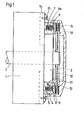
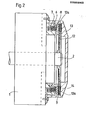
- the disc brake is mounted on the side of a flange 1a of an electric motor 1, which is only indicated schematically, and consists of an electromagnet concentrically surrounding the shaft 2 of the motor 1 with an armature 8, which forms the pressing part, and a brake disk immovably attached to the shaft 2 with a press fit 12 and a fixed brake part 13 forming the outer brake housing.
- the electromagnet has a ring forming the stator shaped housing body 4, which is attached to the motor flange 1a and is cup-shaped, the annular recess 5 being open on the side facing away from the motor 1.
- An annular coil 6 with its bobbin 6a is axially displaceably mounted in the recess 5 and is subject to the action of springs 7 in the form of coil springs.
- These are compression springs which, evenly distributed along the circumference of the stator 4, lie in the recess 5 and are supported on the one hand on the bottom of this recess 5 and on the other hand on the inside of the coil body 6a of the coil 6.
- the annular armature 8 forming the pressing part which surrounds the shaft 2 at a distance, is mounted in a rotationally fixed but axially displaceable manner.
- a few axially directed pins 10 are attached to it, distributed over its circumference, which engage in corresponding openings 11 of the stator 4 in a freely displaceable manner.
- the fixed brake part 13, which forms a brake housing covering the brake with its electromagnet, is fastened to the motor flange 1a by means of screws 15.
- the brake disc 12 consists of resilient, flexible spring steel and has a thickness of only, for example, 0.15 to 0.30 mm, preferably of approximately 0.20 mm. Their diameter is adapted to the size of the motor and in the example considered is approximately 16 cm. Up to an outer diameter of about 20 cm, the Brake disk 12 the above-mentioned preferred thickness of about 0, 2 mm have; for diameters from 20 cm to 30 cm and above, this thickness can be chosen to be correspondingly larger, for example approximately 0.3 mm.
- the air gaps between the brake disc 12 and the brake pad 8 of the armature 9 on the one hand and the brake pad 14 of the brake part 13 on the other hand each amount to approximately 0.2 mm in the released state, so that the edge zone 12a of the brake disc 12 is displaced by approximately 0.2 mm when braking becomes.
- FIGS. 1 and 2 are not to scale.
- the free annular space delimited by the stator 4 of the electromagnet is relatively large, since the diameter of the annular stator 4 can only be chosen to be slightly smaller than the diameter of the electric motor and its radial dimension can be selected to be relatively small. Therefore, this inner annular space, the diameter of which is preferably at least as large as half the motor diameter, can be used to accommodate a further attachment part 3 installed on the motor flange 1a, for example a tachometer generator and / or an angle sensor, thereby achieving a particularly space-saving, compact design .
- a bearing in particular a ball bearing, for the shaft 2 of the motor 1, which is arranged outside the flange 1 a, can also be mounted in this annular space, as a result of which the axial distance between the two, the shaft 2 load-bearing bearings enlarged and thus the tilt stability of the motor rotor is improved.
- Figure 1 shows the disc brake in the released state, which it assumes when the engine is switched on and thus the coil 6 is energized.
- the magnetic force which outweighs the force of the springs 7, pulls the armature 8 back against the stator 4. wherein the axially movable coil 6 is pressed with its coil former 6a against the action of the springs 7 into the recess 5 and the brake disc 12 is released.
- the brake disc 12 is located at an axial distance from the brake pad 9 on the armature 8 as well as from the brake pad 14 on the inside of the fixed brake part 13 and can rotate freely with the shaft 2.
- Figure 2 shows the braking state of the brake, which it assumes when the engine is switched off or the power fails and the coil 6 is thus de-energized.
- the springs 7 press the coil 6 with its bobbin 6a axially outwards against the armature 8, which presses the annular edge zone 12a of the brake disc 12 with elastic deformation of this brake disc against the fixed brake part 13, thus causing the brake disc with its edge zone 12a is firmly clamped between the two brake pads 9 and 14. Due to this action on both sides of the brake disc 12 and the fact that the braking force acts on the outer edge of the brake disc 12, a maximum braking torque is achieved. As soon as the brake disc is released when the brake is released, it resumes due to its inherent elasticity their undeformed shape shown in Figure 1.
- the disc brake according to the invention is particularly suitable for servomotors that are frequently switched on and off. Since it is axially immovable on the shaft 2, a play-free blocking of the motor shaft is guaranteed at a standstill.
- the invention is not limited to the embodiment described, but rather allows for numerous variants with regard to its structural design; in particular, instead of a ring coil 6, a plurality of separate coils distributed uniformly along the circumference of the stator 4 can be provided, for example three coils.
- the braking force and / or the force for releasing the brake can be generated in a manner other than by springs or by electromagnetic forces, for example by pressure-actuated cylinder-piston units.
- pneumatically or hydraulically actuated, double-acting pistons are accommodated, which act on a pressing part corresponding to the armature 8 and are, for example, articulated thereon.
Landscapes
- Engineering & Computer Science (AREA)
- General Engineering & Computer Science (AREA)
- Physics & Mathematics (AREA)
- Electromagnetism (AREA)
- Mechanical Engineering (AREA)
- Power Engineering (AREA)
- Braking Arrangements (AREA)
- Connection Of Motors, Electrical Generators, Mechanical Devices, And The Like (AREA)
Applications Claiming Priority (2)
| Application Number | Priority Date | Filing Date | Title |
|---|---|---|---|
| CH3257/85 | 1985-07-26 | ||
| CH325785 | 1985-07-26 |
Publications (2)
| Publication Number | Publication Date |
|---|---|
| EP0209943A1 true EP0209943A1 (fr) | 1987-01-28 |
| EP0209943B1 EP0209943B1 (fr) | 1992-11-11 |
Family
ID=4252061
Family Applications (1)
| Application Number | Title | Priority Date | Filing Date |
|---|---|---|---|
| EP86201229A Expired - Lifetime EP0209943B1 (fr) | 1985-07-26 | 1986-07-15 | Moteur électrique avec frein à disque |
Country Status (6)
| Country | Link |
|---|---|
| US (1) | US4684838A (fr) |
| EP (1) | EP0209943B1 (fr) |
| JP (1) | JPH0785641B2 (fr) |
| CA (1) | CA1258285A (fr) |
| DE (1) | DE3687092D1 (fr) |
| ES (1) | ES2000719A6 (fr) |
Cited By (10)
| Publication number | Priority date | Publication date | Assignee | Title |
|---|---|---|---|---|
| EP0749803A1 (fr) * | 1995-06-22 | 1996-12-27 | Gildemeister Ag | Dispositif de verrouillage de la broche pour les pièces d'un tour |
| CN102774466A (zh) * | 2012-08-06 | 2012-11-14 | 黄甜雪 | 有摩擦发电与制动一体装置的自行车 |
| CN102774467A (zh) * | 2012-08-06 | 2012-11-14 | 黄甜雪 | 用于自行车摩擦发电和制动一体的装置 |
| CN104836365A (zh) * | 2015-05-27 | 2015-08-12 | 巢惠英 | 一种软启动铝壳电机 |
| EP3239552A4 (fr) * | 2014-12-26 | 2018-11-21 | Oriental Motor Co., Ltd. | Structure de frein à friction |
| CN111946758A (zh) * | 2019-05-16 | 2020-11-17 | 山东力山特智能科技有限公司 | 一种用于直驱卷扬设备的制动器 |
| CN113165627A (zh) * | 2018-11-13 | 2021-07-23 | Chr.迈尔有限公司及两合公司 | 具有整体阻尼结构的电磁可切换制动器 |
| AT524818A1 (de) * | 2021-02-23 | 2022-09-15 | Trumpf Maschinen Austria Gmbh & Co Kg | Verfahren und Vorrichtung zum Umformen eines Werkstückes |
| AT524801A1 (de) * | 2021-02-23 | 2022-09-15 | Trumpf Maschinen Austria Gmbh & Co Kg | Elektromechanischer Spindelantrieb |
| WO2022216569A1 (fr) * | 2021-04-05 | 2022-10-13 | Nexen Group, Inc. | Appareil de commande de mouvement rotatif à jeu nul |
Families Citing this family (28)
| Publication number | Priority date | Publication date | Assignee | Title |
|---|---|---|---|---|
| DE3605088A1 (de) * | 1986-02-18 | 1987-11-05 | Bosch Gmbh Robert | Bedieneinrichtung |
| US5000523A (en) * | 1989-05-17 | 1991-03-19 | General Motors Corporation | Anti-lock braking system with electromagnetic brake |
| US5112116A (en) * | 1989-05-17 | 1992-05-12 | General Motors Corporation | Anti-lock braking system with electromagnetic brake |
| US5669469A (en) * | 1995-04-03 | 1997-09-23 | Otis Elevator Company | Integrated elevator drive machine and brake assembly |
| US5775467A (en) * | 1996-07-29 | 1998-07-07 | General Motors Corporation | Floating electromagnetic brake system |
| US6119818A (en) * | 1998-03-13 | 2000-09-19 | Gustav Magenwirth Gmbh & Co. | Disk brake |
| AT408394B (de) * | 1998-05-29 | 2001-11-26 | Atb Austria Antriebstech Ag | Vorrichtung zum abbremsen von elektromotoren |
| JP2000220674A (ja) * | 1999-02-01 | 2000-08-08 | Tsubakimoto Chain Co | 無励磁作動型電磁ブレーキの消音装置 |
| JP2000220666A (ja) * | 1999-02-01 | 2000-08-08 | Tsubakimoto Chain Co | 無励磁作動型電磁ブレーキの消音装置 |
| ES2195838T3 (es) | 1999-06-17 | 2003-12-16 | Goodrich Control Sys Ltd | Conjunto de frenos. |
| US6162005A (en) * | 1999-08-31 | 2000-12-19 | Kelley Company, Inc. | Vehicle restraint with powered latching member |
| US6439355B1 (en) | 2000-12-18 | 2002-08-27 | The Hilliard Corporation | Electromagnetic spring-actuated brake system |
| RU2262175C1 (ru) * | 2004-03-30 | 2005-10-10 | Орловский государственный технический университет (ОрелГТУ) | Торцовая электрическая машина со встроенным тормозным устройством |
| US8820489B2 (en) * | 2007-03-07 | 2014-09-02 | Arvinmeritor Technology, Llc | Electric motor with static brake |
| US8133143B2 (en) * | 2008-06-16 | 2012-03-13 | Fairfield Manufacturing Company, Inc. | Gear reducer electric motor assembly with internal brake |
| KR101045709B1 (ko) | 2009-05-22 | 2011-06-30 | 김동선 | 회전센서를 구비한 전자브레이크 |
| JP2013103832A (ja) * | 2011-11-16 | 2013-05-30 | Toshiba Elevator Co Ltd | エレベータ制動装置 |
| US9270155B2 (en) * | 2012-05-20 | 2016-02-23 | Mts Systems Corporation | Linear actuator assembly |
| US9994425B1 (en) | 2016-12-12 | 2018-06-12 | Thyssenkrupp Elevator Ag | Compact motor arrangement with integrated brakes and shaft bearings |
| CN107086721B (zh) * | 2017-05-16 | 2023-08-04 | 王心成 | 一种机器人关节用爪式制动器 |
| US10288133B1 (en) * | 2017-12-06 | 2019-05-14 | Warner Electric Technology Llc | Rotational coupling device having means for sealing the interface between the armature and the electromagnet |
| KR102127054B1 (ko) * | 2018-12-20 | 2020-06-25 | 주식회사 두산 | 전기차용 전자 브레이크 시스템 |
| CN109768665B (zh) * | 2018-12-29 | 2020-03-27 | 深圳市优必选科技有限公司 | 一种刹车结构及舵机 |
| US11098774B2 (en) * | 2019-05-01 | 2021-08-24 | Ryan Kleefisch ProStar RC Products | System and method for electro-magnetic applied friction braking in a radio controlled model car |
| GB2588787A (en) * | 2019-11-06 | 2021-05-12 | Safran Electrical & Power | Static brake assembly |
| GB2588786A (en) * | 2019-11-06 | 2021-05-12 | Safran Electrical & Power | Static brake assembly |
| DE102021105318B3 (de) * | 2021-03-05 | 2022-05-05 | Schaeffler Technologies AG & Co. KG | Bremsvorrichtung für eine Radnabenantriebsanordnung |
| WO2025090622A1 (fr) * | 2023-10-23 | 2025-05-01 | Nexen Group, Inc. | Appareil de commande de mouvement rotatif à jeu nul comprenant des broches |
Citations (6)
| Publication number | Priority date | Publication date | Assignee | Title |
|---|---|---|---|---|
| US2077888A (en) * | 1935-07-20 | 1937-04-20 | Master Electric Co | Motor brake |
| US2911548A (en) * | 1955-10-07 | 1959-11-03 | Reliance Electric & Eng Co | Electric motor |
| DE1962406A1 (de) * | 1968-12-13 | 1970-07-02 | Mcculloch Corp | Elektrische Werkzeugmaschine |
| EP0078944A1 (fr) * | 1981-11-05 | 1983-05-18 | Binder Magnete GmbH | Frein à ressort à actionnement électromagnétique |
| EP0146783A2 (fr) * | 1983-12-21 | 1985-07-03 | Westinghouse Electric Corporation | Actionneur robotique électrique de faible poids |
| DE8525585U1 (de) * | 1985-09-07 | 1985-10-31 | Binder Magnete GmbH, 7730 Villingen-Schwenningen | Einscheibenbremse |
Family Cites Families (7)
| Publication number | Priority date | Publication date | Assignee | Title |
|---|---|---|---|---|
| DE287363C (fr) * | ||||
| CH520285A (de) * | 1969-03-21 | 1972-03-15 | Baumueller Gmbh A | An einem Motorgehäuse angeordnete Einscheibenbremse zum Abbremsen der Motorwelle, insbesondere von Elektromotoren |
| DE1951892A1 (de) * | 1969-10-15 | 1971-04-22 | Siemens Ag | Antriebsmotor mit einer Kupplungs- und/oder Bremseinrichtung |
| FR2149017A5 (fr) * | 1971-08-06 | 1973-03-23 | Potain Sa | |
| US4096404A (en) * | 1977-02-03 | 1978-06-20 | Donat Konstantinovich Sukhanov | Hoisting mechanism |
| JPS576360U (fr) * | 1980-06-12 | 1982-01-13 | ||
| JPS5831444U (ja) * | 1981-08-27 | 1983-03-01 | 株式会社甲府明電舎 | 電磁ブレ−キ |
-
1986
- 1986-07-15 EP EP86201229A patent/EP0209943B1/fr not_active Expired - Lifetime
- 1986-07-15 DE DE8686201229T patent/DE3687092D1/de not_active Expired - Lifetime
- 1986-07-16 US US06/886,187 patent/US4684838A/en not_active Expired - Lifetime
- 1986-07-22 ES ES8600484A patent/ES2000719A6/es not_active Expired
- 1986-07-23 JP JP61171923A patent/JPH0785641B2/ja not_active Expired - Lifetime
- 1986-07-25 CA CA000514643A patent/CA1258285A/fr not_active Expired
Patent Citations (6)
| Publication number | Priority date | Publication date | Assignee | Title |
|---|---|---|---|---|
| US2077888A (en) * | 1935-07-20 | 1937-04-20 | Master Electric Co | Motor brake |
| US2911548A (en) * | 1955-10-07 | 1959-11-03 | Reliance Electric & Eng Co | Electric motor |
| DE1962406A1 (de) * | 1968-12-13 | 1970-07-02 | Mcculloch Corp | Elektrische Werkzeugmaschine |
| EP0078944A1 (fr) * | 1981-11-05 | 1983-05-18 | Binder Magnete GmbH | Frein à ressort à actionnement électromagnétique |
| EP0146783A2 (fr) * | 1983-12-21 | 1985-07-03 | Westinghouse Electric Corporation | Actionneur robotique électrique de faible poids |
| DE8525585U1 (de) * | 1985-09-07 | 1985-10-31 | Binder Magnete GmbH, 7730 Villingen-Schwenningen | Einscheibenbremse |
Cited By (17)
| Publication number | Priority date | Publication date | Assignee | Title |
|---|---|---|---|---|
| EP0749803A1 (fr) * | 1995-06-22 | 1996-12-27 | Gildemeister Ag | Dispositif de verrouillage de la broche pour les pièces d'un tour |
| CN102774466A (zh) * | 2012-08-06 | 2012-11-14 | 黄甜雪 | 有摩擦发电与制动一体装置的自行车 |
| CN102774467A (zh) * | 2012-08-06 | 2012-11-14 | 黄甜雪 | 用于自行车摩擦发电和制动一体的装置 |
| CN102774467B (zh) * | 2012-08-06 | 2013-07-10 | 黄甜雪 | 用于自行车摩擦发电和制动一体的装置 |
| EP3239552A4 (fr) * | 2014-12-26 | 2018-11-21 | Oriental Motor Co., Ltd. | Structure de frein à friction |
| US10598235B2 (en) | 2014-12-26 | 2020-03-24 | Oriental Motor Co., Ltd. | Friction brake structure |
| CN104836365A (zh) * | 2015-05-27 | 2015-08-12 | 巢惠英 | 一种软启动铝壳电机 |
| CN113165627A (zh) * | 2018-11-13 | 2021-07-23 | Chr.迈尔有限公司及两合公司 | 具有整体阻尼结构的电磁可切换制动器 |
| CN113165627B (zh) * | 2018-11-13 | 2022-05-24 | Chr.迈尔有限公司及两合公司 | 具有整体阻尼结构的电磁可切换制动器 |
| US11940024B2 (en) | 2018-11-13 | 2024-03-26 | Chr. Mayr Gmbh + Co. Kg | Electromechanically switchable brake having integral damper structure |
| CN111946758A (zh) * | 2019-05-16 | 2020-11-17 | 山东力山特智能科技有限公司 | 一种用于直驱卷扬设备的制动器 |
| AT524818A1 (de) * | 2021-02-23 | 2022-09-15 | Trumpf Maschinen Austria Gmbh & Co Kg | Verfahren und Vorrichtung zum Umformen eines Werkstückes |
| AT524801A1 (de) * | 2021-02-23 | 2022-09-15 | Trumpf Maschinen Austria Gmbh & Co Kg | Elektromechanischer Spindelantrieb |
| AT524801B1 (de) * | 2021-02-23 | 2022-11-15 | Trumpf Maschinen Austria Gmbh & Co Kg | Elektromechanischer Spindelantrieb |
| AT524818B1 (de) * | 2021-02-23 | 2023-01-15 | Trumpf Maschinen Austria Gmbh & Co Kg | Verfahren und Vorrichtung zum Umformen eines Werkstückes |
| US12523268B2 (en) | 2021-02-23 | 2026-01-13 | Trumpf Maschinen Austria Gmbh & Co. Kg. | Electromechanical drive |
| WO2022216569A1 (fr) * | 2021-04-05 | 2022-10-13 | Nexen Group, Inc. | Appareil de commande de mouvement rotatif à jeu nul |
Also Published As
| Publication number | Publication date |
|---|---|
| CA1258285A (fr) | 1989-08-08 |
| EP0209943B1 (fr) | 1992-11-11 |
| JPH0785641B2 (ja) | 1995-09-13 |
| DE3687092D1 (de) | 1992-12-17 |
| ES2000719A6 (es) | 1988-03-16 |
| US4684838A (en) | 1987-08-04 |
| JPS6318940A (ja) | 1988-01-26 |
Similar Documents
| Publication | Publication Date | Title |
|---|---|---|
| EP0209943B1 (fr) | Moteur électrique avec frein à disque | |
| DE69707674T2 (de) | Elektromagnetisch lösbare sicherheits-reibungsbremse | |
| EP2926020B1 (fr) | Dispositif de freinage et moteur électrique | |
| DE19733169A1 (de) | Elektromagnetisch gelüftete Reibungs-Sicherheitsbremse mit zwei unabhängigen Bremskreisen | |
| EP0222312B1 (fr) | Frein à ressort accumulé | |
| EP1883756A1 (fr) | Frein a segment | |
| DE2948728C2 (de) | Elektromagnetisch schaltbare Einflächen-Reibungs-Kupplungs- und -Brems-Kombination | |
| EP0111350B1 (fr) | Moteur électrique équipé d'un frein d'arrêt | |
| DE2901784C2 (de) | Nachstellvorrichtung für den Luftspalt einer elektromagnetisch betätigbaren Scheibenbremse | |
| DE102008026247B4 (de) | Kombinierte Kupplungs- Bremseinheit mit doppelt wirkender Haltebremse | |
| CH676069A5 (fr) | ||
| DE2853802A1 (de) | Geraeuschlos betaetigbare elektromagnetisch lueftbare federdruckbremse | |
| DE29706124U1 (de) | Federdruckbremse | |
| DE69106070T2 (de) | Kupplungseinheit. | |
| EP0078944B1 (fr) | Frein à ressort à actionnement électromagnétique | |
| DE4021310C2 (de) | Elektromagnetisch betätigbare Kupplungs-Bremskombination, insbesondere für Webmaschinen | |
| DE102006007688B4 (de) | Elektromagnetisch betätigbare Schalteinheit | |
| DE19834093C2 (de) | Elektromagnetisch lüftbare Federdruckbremse | |
| DE8525585U1 (de) | Einscheibenbremse | |
| DE7922264U1 (de) | Geraeuschlos betaetigbare elektromagnetisch lueftbare federdruckbremse | |
| DE1463888C (de) | Bremsmotor | |
| DE1286353B (de) | Scheibenbremse, insbesondere elektromagnetisch lueftbare Federdruck-Scheibenbremse | |
| EP0145837A2 (fr) | Moteur de freinage avec desserrage du frein manuel | |
| EP3372461A1 (fr) | Frein électrique | |
| CH617250A5 (fr) |
Legal Events
| Date | Code | Title | Description |
|---|---|---|---|
| PUAI | Public reference made under article 153(3) epc to a published international application that has entered the european phase |
Free format text: ORIGINAL CODE: 0009012 |
|
| AK | Designated contracting states |
Kind code of ref document: A1 Designated state(s): CH DE FR GB IT LI SE |
|
| 17P | Request for examination filed |
Effective date: 19870624 |
|
| 17Q | First examination report despatched |
Effective date: 19890710 |
|
| GRAA | (expected) grant |
Free format text: ORIGINAL CODE: 0009210 |
|
| AK | Designated contracting states |
Kind code of ref document: B1 Designated state(s): CH DE FR GB IT LI SE |
|
| REF | Corresponds to: |
Ref document number: 3687092 Country of ref document: DE Date of ref document: 19921217 |
|
| ITF | It: translation for a ep patent filed | ||
| GBT | Gb: translation of ep patent filed (gb section 77(6)(a)/1977) |
Effective date: 19930106 |
|
| ET | Fr: translation filed | ||
| PLBE | No opposition filed within time limit |
Free format text: ORIGINAL CODE: 0009261 |
|
| STAA | Information on the status of an ep patent application or granted ep patent |
Free format text: STATUS: NO OPPOSITION FILED WITHIN TIME LIMIT |
|
| 26N | No opposition filed | ||
| EAL | Se: european patent in force in sweden |
Ref document number: 86201229.1 |
|
| PGFP | Annual fee paid to national office [announced via postgrant information from national office to epo] |
Ref country code: SE Payment date: 20000705 Year of fee payment: 15 |
|
| PGFP | Annual fee paid to national office [announced via postgrant information from national office to epo] |
Ref country code: FR Payment date: 20010622 Year of fee payment: 16 |
|
| PGFP | Annual fee paid to national office [announced via postgrant information from national office to epo] |
Ref country code: DE Payment date: 20010629 Year of fee payment: 16 Ref country code: CH Payment date: 20010629 Year of fee payment: 16 |
|
| PGFP | Annual fee paid to national office [announced via postgrant information from national office to epo] |
Ref country code: GB Payment date: 20010711 Year of fee payment: 16 |
|
| PG25 | Lapsed in a contracting state [announced via postgrant information from national office to epo] |
Ref country code: SE Free format text: LAPSE BECAUSE OF NON-PAYMENT OF DUE FEES Effective date: 20010716 |
|
| REG | Reference to a national code |
Ref country code: GB Ref legal event code: IF02 |
|
| EUG | Se: european patent has lapsed |
Ref document number: 86201229.1 |
|
| PG25 | Lapsed in a contracting state [announced via postgrant information from national office to epo] |
Ref country code: GB Free format text: LAPSE BECAUSE OF NON-PAYMENT OF DUE FEES Effective date: 20020715 |
|
| PG25 | Lapsed in a contracting state [announced via postgrant information from national office to epo] |
Ref country code: LI Free format text: LAPSE BECAUSE OF NON-PAYMENT OF DUE FEES Effective date: 20020731 Ref country code: CH Free format text: LAPSE BECAUSE OF NON-PAYMENT OF DUE FEES Effective date: 20020731 |
|
| PG25 | Lapsed in a contracting state [announced via postgrant information from national office to epo] |
Ref country code: DE Free format text: LAPSE BECAUSE OF NON-PAYMENT OF DUE FEES Effective date: 20030201 |
|
| GBPC | Gb: european patent ceased through non-payment of renewal fee |
Effective date: 20020715 |
|
| REG | Reference to a national code |
Ref country code: CH Ref legal event code: PL |
|
| PG25 | Lapsed in a contracting state [announced via postgrant information from national office to epo] |
Ref country code: FR Free format text: LAPSE BECAUSE OF NON-PAYMENT OF DUE FEES Effective date: 20030331 |
|
| REG | Reference to a national code |
Ref country code: FR Ref legal event code: ST |
|
| PG25 | Lapsed in a contracting state [announced via postgrant information from national office to epo] |
Ref country code: IT Free format text: LAPSE BECAUSE OF NON-PAYMENT OF DUE FEES;WARNING: LAPSES OF ITALIAN PATENTS WITH EFFECTIVE DATE BEFORE 2007 MAY HAVE OCCURRED AT ANY TIME BEFORE 2007. THE CORRECT EFFECTIVE DATE MAY BE DIFFERENT FROM THE ONE RECORDED. Effective date: 20050715 |
|
| APAH | Appeal reference modified |
Free format text: ORIGINAL CODE: EPIDOSCREFNO |