EP0210063A2 - Berührungssensorgewebe und Verfahren zu seiner Herstellung - Google Patents
Berührungssensorgewebe und Verfahren zu seiner Herstellung Download PDFInfo
- Publication number
- EP0210063A2 EP0210063A2 EP86305572A EP86305572A EP0210063A2 EP 0210063 A2 EP0210063 A2 EP 0210063A2 EP 86305572 A EP86305572 A EP 86305572A EP 86305572 A EP86305572 A EP 86305572A EP 0210063 A2 EP0210063 A2 EP 0210063A2
- Authority
- EP
- European Patent Office
- Prior art keywords
- sheet
- fabric
- sensor
- threads
- pair
- Prior art date
- Legal status (The legal status is an assumption and is not a legal conclusion. Google has not performed a legal analysis and makes no representation as to the accuracy of the status listed.)
- Withdrawn
Links
Images


Classifications
-
- G—PHYSICS
- G06—COMPUTING OR CALCULATING; COUNTING
- G06F—ELECTRIC DIGITAL DATA PROCESSING
- G06F3/00—Input arrangements for transferring data to be processed into a form capable of being handled by the computer; Output arrangements for transferring data from processing unit to output unit, e.g. interface arrangements
- G06F3/01—Input arrangements or combined input and output arrangements for interaction between user and computer
- G06F3/03—Arrangements for converting the position or the displacement of a member into a coded form
- G06F3/041—Digitisers, e.g. for touch screens or touch pads, characterised by the transducing means
- G06F3/045—Digitisers, e.g. for touch screens or touch pads, characterised by the transducing means using resistive elements, e.g. a single continuous surface or two parallel surfaces put in contact
-
- H—ELECTRICITY
- H01—ELECTRIC ELEMENTS
- H01H—ELECTRIC SWITCHES; RELAYS; SELECTORS; EMERGENCY PROTECTIVE DEVICES
- H01H3/00—Mechanisms for operating contacts
- H01H3/02—Operating parts, i.e. for operating driving mechanism by a mechanical force external to the switch
- H01H3/14—Operating parts, i.e. for operating driving mechanism by a mechanical force external to the switch adapted for operation by a part of the human body other than the hand, e.g. by foot
- H01H3/141—Cushion or mat switches
Definitions
- the present invention relates to devices for inputting or determining the coordinates of a location in a two-dimensional system, and more particularly to an electrographic touch sensor employing simplified fabrication and materials of reduced cost resulting in lowered manufacturing costs.
- a device which has come into use for this purpose is known as an eletrographic sensor, generally known as a touch sensor, wherein orthogonal electrical fields produce an X-Y coordinate system.
- a touch sensor wherein orthogonal electrical fields produce an X-Y coordinate system.
- Contact of the sensor at a specific location with a finger or other object causes the generation of signals that are respresentative of the X and Y coordinates of that particular point.
- Orthogonal X and Y electrical fields of the devices of this type have been generated by numerous types of systems. For example, parallel electrodes have been placed on opposite edges on two spaced apart sheets. The electrical field in one direction is generated in one sheet with a voltage applied to the set of electrodes on that sheet, and the orthogonal field is generated in the second sheet in a similar manner.
- the orthogonal electrical fields are generated in a single sheet using various configurations of electrodes along the edges of the sheet, with the electrical potential being applied to appropriate of those electrodes in a proper time sequence. A second sheet is used to make contact whereby the output signals are derived.
- Typical of state-of-the-art touch sensors are those described in U.S. Patents 3,911,215 and 4,220,815.
- a rigid substrate in the form of a sheet of glass, is coated on one side with a resistive layer in the form of an indium-tin-oxide coating.
- the substrate is either flat or, when the touch sensor is to be used over a curved display surface, is contoured to closely fit against that surface.
- E1ectrodes ⁇ - are positioned around the edge of the resistive coating whereby, with appropriate networks, the desired orthogonal electric fields are generated in the resistive coating.
- a flexible conductive sheet is placed proximate the resistive coating whereby pressure against this conductive sheet with a finger or other object causes the same to contact the resistive coating. Small islands or dots of insulation between the resistive coating and the conductive sheet prevent inadvertent contact.
- plastic as the substrate. While this reduces some problems associated with fabrication, the substrate must be preshaped if a curved sensor is desired. The curved substrates often do not closely match the tube curvature and because these sensors are relatively thick, some visual parallax results due to the offset from the display. Even with the use of plastic, fabrication costs are high. Also, plastic substrates are more subject to damage during use. These devices, both plastic and glass, require separate fix- turing for the individual sizes that are to be fabricated.
- a single-sheeted fabric sensor is shown and described in U.S. Patent 4,442,317, issued to L. H. M. Jandrell on April 10, 1984.
- This sensor employes a conductive fabric screen and a probe (stylus) to contact the screen at selected points to obtain positional information.
- This sensor if the filaments are dark (e.g., black), provides an antiglare surface like that disclosed in U.S. Patent 4,253,737 issued to E. J. Thomsen, et al.
- a stylus-operated sensor is not considered a viable form of "communication" in the present market. It, like sensors operated by light pens, is outmoded for general applications.
- One of the problems is that discussed in U.S. Patent 4,442,317 namely, physical wear caused by the stylus. However, the main problem is the non-acceptance of users.
- the present invention provides an electrographic sensor for providing positional information related to a selected point/region touched by a user, which comprises:
- first and further sheets is fabricated from electrically conductive threads.
- a sensor panel according to the invention can be manufactured from relatively inexpensive materials as contrasted to conventional sensors.
- a two active sheet touch sensor construction can be made that can be used over a curved surface display that does not require preforming of the sensor components.
- a thin two active sheet touch sensor panel can be used that substantially reduces visual parallax when used over a display.
- a light weight two active sheet touch sensor panel can be made whereby mounting thereof relative to a display is simplified.
- a two active sheet touch sensor panel fabricated from fabric can be made which substantially reduces visual problems such as Moire-type patterns.
- a two sheeted touch sensor panel wherein at least one of the active sheets thereof is fabricated from conductive threads.
- the threads can be unidirectional threads, or can be threads woven or overlaid in multidirections. For most applications it is important to orient the threads to prevent Moire-type patterns when both active sheets comprise conductive threads.
- both layers of the sensor preferably comprise a fabric containing conductive threads.
- the orthogonal electric fields can be generated in one fabric layer, or both layers can be utilized to obtain the orthogonal fields.
- the two layers are prevented from inadvertent contact (particularly important in curved sensors) by separating means. These may be insulating dots, insulating threads, or other suitable means distributed between the active sheets of the sensor. Particularly when the sensor is flat, an air gap can be used as the separating means and will provide sufficient separation.
- Sensors according to the invention can be used a opaque sensors (not depending on light transmission), or as light transmitting sensors.
- the following description is to an embodiment of sensor that can be used on a display wherein light transmission through the sensor is desired.
- Such a sensor has the following three to five basic component layers listed in their order from the display surface out toward the touch panel user. These are: a substrate (optional); a first resistive layer; a separator; a second resistive layer; and an overlay (optional).
- a substrate is desired to provide mechanical form and rigidity (discussed below with regard to Figure 4).
- This substrate can take the form of a glass panel, for example. Typically, this is a 0.15 cm (1/16 inch) to 0.35 ' cm (1/8 inch) thick glass sheet that is optically clear.
- the glass is preformed into a complimentary contour (e.g., spherical or cylindrical).
- the substrate can be a plastic sheet, preformed if necessary, of substantially the same thickness as the glass substrate. The plastic substrate, although less rigid, is more break resistant.
- the first resistive layer and the second resistive layer have substantially the same choice of constructions.
- the following discussion for the layer closest to the display surface is thus generally applicable to the second resistive sheet or layer.
- This layer can be a single set of parallel conductive threads such as the Badische threads described above, placed equal distances apart in the direction of current flow (i.e., for a single axis layer). Center-to-center thread spacing is selected to produce a desired light transmission and overall resistivity as required for a particular application of the fabric touch panel. Closer spacing reduce light transmission and increase electrical conductivity (reduced resistivity), whereas wider spacings have the opposite effect. Typical spacing for this single set of threads is between about 0.005 and 0.10 inches. These threads can have a resistivity from about 10 4 to about 10 9 ohms per inch.
- the first resistive layer can also consist of two sets of conductive threads, with threads in each set being parallel.
- the second set would be positioned at some selected angle to those of the first set, and typically would be perpendicular to those of the first set, either overlayed on the first set or woven into a true fabric as woof and weft threads.
- Use of a second set of threads reduces the overall light transmission of the sensor; however, it provides a means of cross communication between all threads and improves the effective resistance uniformity of the layer and hence will provide more accurate positional information during use.
- this layer can be used either as a single axis sheet or as a combined two axis sheet.
- Spacing of the threads can be identical in both directions or can be selected to be non- identical, for example, to balance the overall resistance in the two axis directions to compensate for aspect ratios. Closer spacings of the threads of the fabric (either of the two sets of threads) provide more fabric stability and thus the fabric is more easily handled in a production environment.
- Still another construction for the first resitive layer is a non-fabric layer that can consist of a resistive coating applied directly to a substrate.
- a resistive coating applied directly to a substrate.
- this can be an indium-tin-oxide or tin-oxide coating.
- This coating is especially useful to be operated as a two axis layer, and provides increased light transmission as compared to a fabric layer. It is, however, a more expensive form of resistive layer.
- a separator layer for the present invention is to inhibit contact between the two layers of resistive material and to control the amount of force required to achieve intentional contact therebetween. For example, some applications of the sensor are such that a higher amount of force is desirable before positional information is generated. In the case of curved sensors, the elastic nature of the threads would result in contact between the sheets unless some dispersed insulation means is employed. The cosmetic appearance of a sensor is an important factor, in the choice of a suitable separator.
- One such separator means employs non-conductive threads that will be inconspicuous between the conductive threads.
- black non-conductive ' threads of similar diameters (0.002 to 0.010 inches) on a spacing of about 0.1 to 0.3 inches will provide adequate separation between the resistive layers or sheets. Closer spacing requires more force to activate the sensor panel.
- an activation force 1 to 16 oz. can be obtained by thread spacing of between 0.1 and 0.2 inches when the separator threads have a diameter between 0.005 and 0.01 inches.
- the separator threads can be oriented horizontally, vertically, or at an angle. Prior use of threads, in the form of a net, as an insulator layer is described in U.S. Patent 3,798,370.
- Another separating means is a spaced-apart array of small insulating dots applied using a screen process or the like.
- This array can be a rectangular spacing, for example, of dots having a diameter of 0.005 to 0.025 inches and a height of up to a few thousandths of an inch (e.g., up to about 0.005 inch). Spacing of the dots, as well as the height, is used to select a desired activation force. Spacing is typically 0.025 to 0.50 inches. More details of the dot separators are given in the aforementioned U.S. Patent 4,220,815.
- the present fabric sensor is operated as a flat sensor in contrast to being curved, the layers normally will be maintained apart adequately by use of a physical spacer around the periphery of the sensor and an air gap in the, operating portion of the sensor.
- the second resistive layer can be substantially like the first resistive layer, i.e., it can be a fabric of either unidirectional conductive threads, or two sets of threads oriented at an angle.
- it can be a non-fabric layer if the first resistive layer is fabric.
- the non-fabric embodiment can be an indium-tin-oxide coating, a metal film coating, or a multilayer corn- -. posite conductive coating applied to a thin plastic film.
- Such a plastic film can act as a protective overlay layer, and its thickness is typically in the range of 0.001 to 0.015 inches.
- both resistive layers are fabric
- detrimental visual effects can exist unless a construction is utilized to prevent the same.
- the fine crossed threads of the two layers can create Moire-type interference patterns which are distracting to a user of the panel. These interference patterns can be elimiated by orienting the threads of one layer at an oblique angle to the threads of the other layer.
- wide spacing of threads minimizes the effects.
- other controlled interrelation between the spacing of threads in the layers minimizes or eliminates the detrimental visual effects.
- an overlay for the fabric sensor is optional; however, such overlay seals against possible contaminants, eliminates dust accumulation, provides abrasion resistance and reduces exposure to moisture. Since the fabric provides an excellent glare reduction (as in U.S. Patent 4,442,317 and 4,253,737 patents cited above), an overlay can reintroduce some glare. Also, an overlay adds complexity to the construction. If an overlay is to be used, it can be, for example, a thin transparent polyester sheet or similar formable material approximately 0.002 to 0.010 inch thick preshaped, if necessary, to the contour of the display device. Also, the overlay can be fabricated of a thin transparent elastomeric material such as polyurethane film.
- the elastomer would conform to the shape of the sensor and thus would not require prefoming as in the case of the plastic overlay. Still another embodiment of an overlay would be provided by applying a non-conducting clear filler material to the second (top) fabric resistive layer.
- a typical fabrication of a sensor according to this invention is as follows.
- a thin rectangular insulating frame is first provided which has an open central region for the transparent active area of the sensor and a non- transparent border region for the mounting of the other components.
- the frame material is flexible so that the resultant touch panel can be bent to conform to the surface of the display device.
- a single set of black non-conductive monofilament threads of 0.005 inch diameter are wound taut in a horizontal (X) direction around the frame in rows having a center-to-center spacing of 0.20 inches to produce the separator layer.
- Resistive black monofilament threads having a diameter of 0.002 inches and a resistance of 5 x 10 5 ohms per inch are then wound taut about the frame in a vertical (Y) orientation with a spacing of 0.05 inches. This provides one set of threads for the first and second resistive layers. A second winding of the same thread is applied horizontally (X) to produce the second set of threads for each layer. Thereupon, the threads are secured to the frame with an appropriate adhesive. This is followed by severing th connection of threads between the two layers.
- Strip electrodes are applied to both sides of the frame to provide for the application of appropriate voltages to the fabric resistive sheets of the sensor panel. These electrodes can be applied either before the winding with the conductive threads, or after the winding is complete. Suitable connecting leads are attached to the electrodes so as to provide for connection to circuitry associated with the fabric panel.
- a touch sensor panel is provided having unique characteristics when compared to panels of the prior art.
- the panel is extremely thin and thus has little offset from a display device with the attendant reduction in parallax problems.
- the nature of the fabric substantially reduces problems of glare, and a proper orientation of one fabric layer with the other eliminates Moire-type visual interference problems.
- the ease of contruction substantially reduces fabrication costs.
- each of the sheets 12, 14 is a fabric made up of fine threads 16, 18 and 20, 22, respectively.
- These fabrics of this embodiment can be either interwoven woof and weft threads, or can have the threads just overlapping.
- these threads can be about 50 microns in diameter, with a resistance per unit length of about 2 x 10⁵ ohms/cm.
- Such thread is available from Badische Corporation, Williamsburg, Virginia (Badische type F-901, 20/1 conductive 6 monofilament).
- the threads typically are uniformly spaced on 0.050 inch centers throughout the fabric. It will be apparent to one versed in the art that a fabric having a specific resistivity can be produced by selecting the proper size, spacing, and resistivity of the thread. Although this Figure 1 indicates that the threads are arranged perpendicularly, other orientations are within the scope of the present invention.
- Woven fabric can be used such as that available from TETKO, Inc., Elmsford, New York (Type 3C-3C-130). This fabric contains threads of about 50 microns on 180 micron centers and has a sheet resistivity of about 3000 ohms per square.
- a suitable means of pro-,, viding a separator to prevent the inadvertent contact is a selected distribution of small insulator islands or dots 24 attached to one of the sheets (e.g., sheet 14).
- the functions of these dots, and their method of formation, are described in the above mentioned U.S. Patents 3,911,215 and 4,220,815. Discussed hereinafter are other suitable separator means.
- FIG. 2A A view of the resitivity of the thread/fabric, electrical potentials can be generated in the sheets 12, 14 in substantially the same manner as employed in conventional touch sensors.
- One method of accomplishing such generation is illustrated in Figure 2A.
- a pair of oppositely disposed bar-type electrodes 26, 28 is applied to sheet 12, with another pair of oppositely disposed electrodes 30, 32 applied to sheet 14 such that fields produced in the two sheets will be oriented orthogonally.
- Each sheet in this embodiment is thus a "single axis" sheet.
- FIG. 2B An alternate electrode construction is illustrated in Figure 2B.
- This is the type of electrode construction (spot electrodes 34) utilized in the above mentioned U.S. Patents 3,911,215 and 4,220,815; all electrodes 34 being on one sheet (e.g., sheet 14) such that the two orthogonal fields are both generated in this sheet.
- the top sheet e.g., sheet 12
- This embodiment is referred to as a "two axis" sheet.
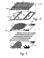
- Figure 4 depicts at least two other possible embodiments of the present invention.
- the sensor 10A utilizes only an upper fabric sheet 12A.
- sheet 12A is fabricated of only unidirectional threads 16; i.e., cross threads 18 are not present. While this construction may not be preferred for all applications, it is within the scope of the present invention. It should be recognized that the unidirectional threads 16 can have any desired orientation and not only the direction illustrated in this figure. If this sheet is to have bar-type electrodes attached thereto, as in Figure 2A, the electrodes are attached so as to join ends of the threads 16 (current flow along the threads).
- the sensor 10A of Figure 4 differs in a futher way from the sensor 10 of Figures 1 through 3.
- the second sheet 14A is ma4/ up of a non-fabric resistive layer or coating 38 as applied to a rigid, semiflexible or flexible substrate 40.
- the coating 38 can typically be a coating of the type identified in the above mentioned U.S. Patents 3,911,215 and 4,220,815, namely an indium-tin-oxide, or any other suitable resistive material. Electrodes of conventional configuration are attached thereto for proper performance of the sensor. Typically separators in the form of lines of insulation 41 are attached to the coating 38 when the sensor is to be curved to normally maintain threads 16 separated from coating 38. These lines of insulation 41 (or threads as in Figure 5) are oriented at a substantial angle (e.g., 90 degrees) to the resistive threads 16. Alternatively, the separator for curved sensors can be a grid of insulating lines or threads.
- the fabric sheet is shown as being made up of unidirectional threads, a fabric cloth can also be used as one sheet with the resistive coating 38 as the second sheet.
- the upper sheet 12B is fabricated such that the threads 16, 18 thereof are oriented at an oblique angle to the threads 20, 22 of the lower sheet 14B.
- an angular orientation of about 35 to 40 degrees will eliminate the Moire-type interference pattern. The exact orientation for any unit will depend upon the thread diameter and spacing, and the degree of correction that is desired.
- non-conductive threads 42 serve as separators to prevent inadvertent contact between sheet 12B and sheet 14B.
- FIG. 6 An embodiment of the present touch sensor useful for retrofit and temporary applications is illustrated at 60 in Figure 6.
- This embodiment utilizes an open frame having two pairs of opposite walls 44, 46 and 48, 50. Each of these walls is contoured along one edge (e.g., 52, 54, 56, 58) substantially to match the contour of a video tube face (not shown).
- the sheets 62, 64 are separated by any suitable means (insulating threads, etc.) throughout the region of overlap. If desired, reinforcing regions (not shown) can be included on the sheets where the sheets bend over the edges of the frame to prevent breakage of threads or other damage.
- Electrodes e.g., electrode 66 on sheet 64
- a second electrode would be attache4 to fabric sheet 64 on the outside of wall 48.
- fabric sheet 62 has a pair of electrodes: electrode 68 on wall 46 and a second electrode (not shown) on the outside of wall 44.
- Each of the electrodes is provided with an electrical lead, such as lead 70 to electrode 66, whereby such electrodes are connected to appropriate circuitry. If desired these leads can be provided within the walls of the frame.
- Figure 6 utilizes the generation of an electric field in one direction in sheet 64. This is like the sensor illustrated in Figure 2A. Alternately, by using a different array of electrodes, a sensor equivalent to that of Figure 2B can be constructed on the frame for retrofit and temporary applications.
Landscapes
- Engineering & Computer Science (AREA)
- General Engineering & Computer Science (AREA)
- Theoretical Computer Science (AREA)
- Human Computer Interaction (AREA)
- Physics & Mathematics (AREA)
- General Physics & Mathematics (AREA)
- Position Input By Displaying (AREA)
- Laminated Bodies (AREA)
Applications Claiming Priority (2)
| Application Number | Priority Date | Filing Date | Title |
|---|---|---|---|
| US06/756,733 US4659873A (en) | 1985-07-19 | 1985-07-19 | Fabric touch sensor and method of manufacture |
| US756733 | 1991-09-09 |
Publications (2)
| Publication Number | Publication Date |
|---|---|
| EP0210063A2 true EP0210063A2 (de) | 1987-01-28 |
| EP0210063A3 EP0210063A3 (de) | 1988-11-17 |
Family
ID=25044820
Family Applications (1)
| Application Number | Title | Priority Date | Filing Date |
|---|---|---|---|
| EP86305572A Withdrawn EP0210063A3 (de) | 1985-07-19 | 1986-07-18 | Berührungssensorgewebe und Verfahren zu seiner Herstellung |
Country Status (3)
| Country | Link |
|---|---|
| US (1) | US4659873A (de) |
| EP (1) | EP0210063A3 (de) |
| JP (1) | JPS6263332A (de) |
Cited By (7)
| Publication number | Priority date | Publication date | Assignee | Title |
|---|---|---|---|---|
| AU632112B2 (en) * | 1989-04-14 | 1992-12-17 | Telematique Videotex Francaise T.V.F. | Portable microcomputer |
| GB2343516A (en) * | 1998-11-03 | 2000-05-10 | Univ Brunel | Fabric pressure sensor comprising conductive layers or strips and an insulating separator |
| GB2350683A (en) * | 1999-05-12 | 2000-12-06 | Univ Brunel | Conductive textile assembly for a pressure sensor |
| US7365031B2 (en) | 2000-04-03 | 2008-04-29 | Intelligent Textiles Limited | Conductive pressure sensitive textile |
| US8298968B2 (en) | 2004-02-27 | 2012-10-30 | Intelligent Textiles Limited | Electrical components and circuits constructed as textiles |
| US10519575B2 (en) | 2015-12-18 | 2019-12-31 | Intelligent Textiles Limited | Conductive fabric, method of manufacturing a conductive fabric and apparatus therefor |
| CN111240508A (zh) * | 2018-11-28 | 2020-06-05 | 尚科纺织企业工业及贸易公司 | 大面积触摸织物 |
Families Citing this family (93)
| Publication number | Priority date | Publication date | Assignee | Title |
|---|---|---|---|---|
| US4715235A (en) * | 1985-03-04 | 1987-12-29 | Asahi Kasei Kogyo Kabushiki Kaisha | Deformation sensitive electroconductive knitted or woven fabric and deformation sensitive electroconductive device comprising the same |
| USRE38419E1 (en) | 1986-05-13 | 2004-02-10 | Ncr Corporation | Computer interface device |
| IT1206891B (it) * | 1987-02-05 | 1989-05-11 | L E D A Logarithmic Electrical | Resistore elettrico atto ad essere utilizzato come elemento conduttore di elettricita in un circuito elettrico e procedimento per realizzaretale resistore |
| US5019677A (en) * | 1990-07-11 | 1991-05-28 | Microslate Corp. | Computer input device |
| US6539363B1 (en) | 1990-08-30 | 2003-03-25 | Ncr Corporation | Write input credit transaction apparatus and method with paperless merchant credit card processing |
| US5149918A (en) * | 1990-10-29 | 1992-09-22 | International Business Machines Corporation | Touch sensitive overlay |
| US5227590A (en) * | 1991-05-17 | 1993-07-13 | Ncr Corporation | Handwriting capture device |
| US5220136A (en) * | 1991-11-26 | 1993-06-15 | Elographics, Inc. | Contact touchscreen with an improved insulated spacer arrangement |
| JPH11238423A (ja) * | 1998-02-20 | 1999-08-31 | Porimatec Kk | 接点キースイッチおよびその製造法 |
| GB9820909D0 (en) * | 1998-09-26 | 1998-11-18 | Electrotextiles Comp Ltd | Detector constructed from fabric |
| GB2341931B (en) * | 1998-09-26 | 2002-08-14 | Electrotextiles Co Ltd | Fabric constructed from electrically conducting fibres |
| GB2341930B (en) * | 1998-09-26 | 2002-07-31 | Electrotextiles Co Ltd | Detector constructed from fabric |
| US6369804B1 (en) * | 1998-09-26 | 2002-04-09 | Eleksen Limited | Detector constructed from fabric having non-uniform conductivity |
| US6333736B1 (en) | 1999-05-20 | 2001-12-25 | Electrotextiles Company Limited | Detector constructed from fabric |
| JP2003500759A (ja) * | 1999-05-20 | 2003-01-07 | エレクセン リミテッド | 機械的相互作用の検出 |
| US6639162B2 (en) | 2000-03-30 | 2003-10-28 | Electrotextiles Company Limited | Input device |
| HK1048192B (en) * | 2000-03-30 | 2005-08-26 | Eleksen Limited | Detector made of conductive fiber |
| GB0011829D0 (en) * | 2000-05-18 | 2000-07-05 | Lussey David | Flexible switching devices |
| US7289083B1 (en) * | 2000-11-30 | 2007-10-30 | Palm, Inc. | Multi-sided display for portable computer |
| US7348964B1 (en) * | 2001-05-22 | 2008-03-25 | Palm, Inc. | Single-piece top surface display layer and integrated front cover for an electronic device |
| US8384674B1 (en) | 2001-01-30 | 2013-02-26 | Hewlett-Packard Development Company, L.P. | Integrated enclosure/touch screen assembly |
| US6992659B2 (en) | 2001-05-22 | 2006-01-31 | Palmone, Inc. | High transparency integrated enclosure touch screen assembly for a portable hand held device |
| DE10129183A1 (de) * | 2001-06-19 | 2003-01-02 | Aso Gmbh Antriebs Und Steuerun | Sicherheitskontaktmatte |
| WO2003025961A1 (de) * | 2001-09-19 | 2003-03-27 | Iee International Electronics & Engineering S.A. | Schaltelement in folienbauweise |
| WO2003052541A2 (de) * | 2001-12-14 | 2003-06-26 | Infineon Technologies Ag | Keypad in textilien mit kapazativer ausleseschaltung |
| DE10200146B4 (de) * | 2002-01-04 | 2011-05-05 | Freundes- und Förderkreis des Institutes für Textiltechnik der RWTH Aachen e.V. | Textile Schaltmatrix und Herstellungsverfahren dafür |
| GB0209888D0 (en) * | 2002-04-30 | 2002-06-05 | Koninkl Philips Electronics Nv | Switch |
| CN100521020C (zh) * | 2003-06-06 | 2009-07-29 | 皇家飞利浦电子股份有限公司 | 一种可延伸的织物开关 |
| WO2005011415A1 (en) * | 2003-08-01 | 2005-02-10 | Santa Fe Science And Technology, Inc. | Multifunctional conducting polymer structures |
| GB0402191D0 (en) * | 2004-02-02 | 2004-03-03 | Eleksen Ltd | Linear sensor |
| GB0406079D0 (en) * | 2004-03-18 | 2004-04-21 | Eleksen Ltd | Sensor response |
| GB2431045B (en) * | 2005-09-09 | 2008-02-13 | Eleksen Ltd | Electrical conductor element |
| TW200728699A (en) * | 2006-01-23 | 2007-08-01 | Chang-Ming Yang | Fabric-based strain gauge |
| KR100938684B1 (ko) * | 2007-10-16 | 2010-01-25 | 코오롱글로텍주식회사 | 전자 원단 및 이의 제조방법 |
| CN101458600B (zh) * | 2007-12-14 | 2011-11-30 | 清华大学 | 触摸屏及显示装置 |
| CN101470566B (zh) * | 2007-12-27 | 2011-06-08 | 清华大学 | 触摸式控制装置 |
| CN101458594B (zh) * | 2007-12-12 | 2012-07-18 | 清华大学 | 触摸屏及显示装置 |
| CN101458596B (zh) * | 2007-12-12 | 2011-06-08 | 北京富纳特创新科技有限公司 | 触摸屏及显示装置 |
| CN101676832B (zh) * | 2008-09-19 | 2012-03-28 | 清华大学 | 台式电脑 |
| CN101458604B (zh) * | 2007-12-12 | 2012-03-28 | 清华大学 | 触摸屏及显示装置 |
| CN101464763B (zh) * | 2007-12-21 | 2010-09-29 | 清华大学 | 触摸屏的制备方法 |
| CN101458606B (zh) * | 2007-12-12 | 2012-06-20 | 清华大学 | 触摸屏、触摸屏的制备方法及使用该触摸屏的显示装置 |
| CN101419518B (zh) * | 2007-10-23 | 2012-06-20 | 清华大学 | 触摸屏 |
| CN101458603B (zh) * | 2007-12-12 | 2011-06-08 | 北京富纳特创新科技有限公司 | 触摸屏及显示装置 |
| CN101419519B (zh) * | 2007-10-23 | 2012-06-20 | 清华大学 | 触摸屏 |
| CN101470559B (zh) * | 2007-12-27 | 2012-11-21 | 清华大学 | 触摸屏及显示装置 |
| CN101458605B (zh) * | 2007-12-12 | 2011-03-30 | 鸿富锦精密工业(深圳)有限公司 | 触摸屏及显示装置 |
| CN101458609B (zh) * | 2007-12-14 | 2011-11-09 | 清华大学 | 触摸屏及显示装置 |
| CN101458598B (zh) * | 2007-12-14 | 2011-06-08 | 清华大学 | 触摸屏及显示装置 |
| CN101655720B (zh) * | 2008-08-22 | 2012-07-18 | 清华大学 | 个人数字助理 |
| CN101458595B (zh) * | 2007-12-12 | 2011-06-08 | 清华大学 | 触摸屏及显示装置 |
| CN101458602B (zh) * | 2007-12-12 | 2011-12-21 | 清华大学 | 触摸屏及显示装置 |
| CN101656769B (zh) * | 2008-08-22 | 2012-10-10 | 清华大学 | 移动电话 |
| CN101470558B (zh) * | 2007-12-27 | 2012-11-21 | 清华大学 | 触摸屏及显示装置 |
| CN101458599B (zh) * | 2007-12-14 | 2011-06-08 | 清华大学 | 触摸屏、触摸屏的制备方法及使用该触摸屏的显示装置 |
| CN101458608B (zh) * | 2007-12-14 | 2011-09-28 | 清华大学 | 触摸屏的制备方法 |
| CN101620454A (zh) * | 2008-07-04 | 2010-01-06 | 清华大学 | 便携式电脑 |
| CN101458593B (zh) * | 2007-12-12 | 2012-03-14 | 清华大学 | 触摸屏及显示装置 |
| CN101470560B (zh) * | 2007-12-27 | 2012-01-25 | 清华大学 | 触摸屏及显示装置 |
| CN101458597B (zh) * | 2007-12-14 | 2011-06-08 | 清华大学 | 触摸屏、触摸屏的制备方法及使用该触摸屏的显示装置 |
| CN101458975B (zh) * | 2007-12-12 | 2012-05-16 | 清华大学 | 电子元件 |
| CN101458601B (zh) * | 2007-12-14 | 2012-03-14 | 清华大学 | 触摸屏及显示装置 |
| CN101458607B (zh) * | 2007-12-14 | 2010-12-29 | 清华大学 | 触摸屏及显示装置 |
| CN101464757A (zh) * | 2007-12-21 | 2009-06-24 | 清华大学 | 触摸屏及显示装置 |
| CN101464764B (zh) * | 2007-12-21 | 2012-07-18 | 清华大学 | 触摸屏及显示装置 |
| US8574393B2 (en) * | 2007-12-21 | 2013-11-05 | Tsinghua University | Method for making touch panel |
| CN101464766B (zh) * | 2007-12-21 | 2011-11-30 | 清华大学 | 触摸屏及显示装置 |
| CN101470565B (zh) * | 2007-12-27 | 2011-08-24 | 清华大学 | 触摸屏及显示装置 |
| CN101464765B (zh) * | 2007-12-21 | 2011-01-05 | 鸿富锦精密工业(深圳)有限公司 | 触摸屏及显示装置 |
| US20090273577A1 (en) * | 2008-04-30 | 2009-11-05 | Apple Inc. | Moire-Free Touch Screen with Tilted or Curved ITO Pattern |
| US8237677B2 (en) * | 2008-07-04 | 2012-08-07 | Tsinghua University | Liquid crystal display screen |
| US8390580B2 (en) * | 2008-07-09 | 2013-03-05 | Tsinghua University | Touch panel, liquid crystal display screen using the same, and methods for making the touch panel and the liquid crystal display screen |
| US8982051B2 (en) * | 2009-03-30 | 2015-03-17 | Microsoft Technology Licensing, Llc | Detecting touch on a surface |
| US9317140B2 (en) * | 2009-03-30 | 2016-04-19 | Microsoft Technology Licensing, Llc | Method of making a multi-touch input device for detecting touch on a curved surface |
| CN101924816B (zh) * | 2009-06-12 | 2013-03-20 | 清华大学 | 柔性手机 |
| EP2441867A1 (de) * | 2010-10-18 | 2012-04-18 | Sefar Ag | Dehnungssensor und Verfahren zum Messen einer Dehnung eines Textils |
| EP2760363A4 (de) | 2011-09-29 | 2015-06-24 | Magic Leap Inc | Taktiler handschuh zur mensch-computer-interaktion |
| JP5871129B2 (ja) * | 2012-02-13 | 2016-03-01 | 日産自動車株式会社 | 布状圧力センサー |
| EP2985750A4 (de) * | 2013-04-10 | 2016-08-24 | Fujifilm Corp | Leitfähige folie, anzeigevorrichtung damit sowie beurteilung und bestimmungsverfahren für ein verdrahtungsmuster einer leitfähigen folie |
| CN114296574B (zh) * | 2014-09-30 | 2024-12-27 | 苹果公司 | 织物感测设备 |
| KR101938215B1 (ko) * | 2015-08-26 | 2019-01-14 | 주식회사 퓨처플레이 | 스마트 인터렉션 장치 |
| DE102016106071A1 (de) | 2016-04-04 | 2017-10-05 | Pilz Gmbh & Co. Kg | Gewebe mit mehreren Gewebelagen und Verfahren zu dessen Herstellung |
| DE102016106074A1 (de) | 2016-04-04 | 2017-10-05 | Pilz Gmbh & Co. Kg | Gewebe mit mehreren Gewebelagen |
| JP6741995B2 (ja) | 2016-04-15 | 2020-08-19 | パナソニックIpマネジメント株式会社 | フレキシブルタッチセンサおよびその製造方法 |
| US10638618B1 (en) * | 2016-07-12 | 2020-04-28 | Apple Inc. | Cosmetic integration of displays |
| US10688714B2 (en) * | 2016-07-28 | 2020-06-23 | Purdue Research Foundation | Methods and systems for fabricating elastomer-based electronic devices and devices formed thereby |
| IT201600094342A1 (it) * | 2016-09-20 | 2018-03-20 | Plug & Wear Srl | Metodo per la produzione di un sensore tessile |
| EP3473976B1 (de) * | 2017-10-20 | 2019-09-25 | C.R.F. Società Consortile per Azioni | Verformungserfassungsvorrichtung mit einem multifunktionsgewebe mit geflockten leitfähigen schussfäden |
| KR102488564B1 (ko) * | 2018-04-11 | 2023-01-13 | 삼성전자 주식회사 | 직조 양식 하우징 및 이를 사용하는 전자 장치 |
| US11042233B2 (en) * | 2018-05-09 | 2021-06-22 | Apple Inc. | Finger-mounted device with fabric |
| US11507206B2 (en) | 2019-05-13 | 2022-11-22 | Microsoft Technology Licensing, Llc | Force-sensing input device |
| US11591850B2 (en) | 2019-11-01 | 2023-02-28 | Crestron Electronics, Inc. | Capacitive touch fabric and system and method for shade control via the capacitive touch fabric |
| WO2022040492A1 (en) * | 2020-08-21 | 2022-02-24 | Board Of Regents, The University Of Texas System | Two-dimensional resistance temperature detectors and related methods for determining average temperature over a surface |
Family Cites Families (5)
| Publication number | Priority date | Publication date | Assignee | Title |
|---|---|---|---|---|
| US3911215A (en) * | 1974-03-18 | 1975-10-07 | Elographics Inc | Discriminating contact sensor |
| US4442317A (en) * | 1981-09-14 | 1984-04-10 | Sun-Flex Company, Inc. | Coordinate sensing device |
| US4455450A (en) * | 1981-09-25 | 1984-06-19 | Margolin George D | Digitizing tablet |
| US4493104A (en) * | 1981-12-11 | 1985-01-08 | Moore Business Forms, Inc. | Character recognition device |
| JPS5933070Y2 (ja) * | 1982-07-03 | 1984-09-14 | アルプス電気株式会社 | 入力装置 |
-
1985
- 1985-07-19 US US06/756,733 patent/US4659873A/en not_active Expired - Fee Related
-
1986
- 1986-07-18 EP EP86305572A patent/EP0210063A3/de not_active Withdrawn
- 1986-07-19 JP JP61170712A patent/JPS6263332A/ja active Pending
Cited By (10)
| Publication number | Priority date | Publication date | Assignee | Title |
|---|---|---|---|---|
| AU632112B2 (en) * | 1989-04-14 | 1992-12-17 | Telematique Videotex Francaise T.V.F. | Portable microcomputer |
| GB2343516A (en) * | 1998-11-03 | 2000-05-10 | Univ Brunel | Fabric pressure sensor comprising conductive layers or strips and an insulating separator |
| GB2350683A (en) * | 1999-05-12 | 2000-12-06 | Univ Brunel | Conductive textile assembly for a pressure sensor |
| GB2350683B (en) * | 1999-05-12 | 2003-05-07 | Univ Brunel | Conductive textile assembly |
| US7365031B2 (en) | 2000-04-03 | 2008-04-29 | Intelligent Textiles Limited | Conductive pressure sensitive textile |
| US8298968B2 (en) | 2004-02-27 | 2012-10-30 | Intelligent Textiles Limited | Electrical components and circuits constructed as textiles |
| US8669195B2 (en) | 2004-02-27 | 2014-03-11 | Intelligent Textiles Limited | Electrical components and circuits constructed as textiles |
| US10519575B2 (en) | 2015-12-18 | 2019-12-31 | Intelligent Textiles Limited | Conductive fabric, method of manufacturing a conductive fabric and apparatus therefor |
| CN111240508A (zh) * | 2018-11-28 | 2020-06-05 | 尚科纺织企业工业及贸易公司 | 大面积触摸织物 |
| CN111240508B (zh) * | 2018-11-28 | 2024-03-08 | 尚科纺织企业工业及贸易公司 | 大面积触摸织物 |
Also Published As
| Publication number | Publication date |
|---|---|
| JPS6263332A (ja) | 1987-03-20 |
| US4659873A (en) | 1987-04-21 |
| EP0210063A3 (de) | 1988-11-17 |
Similar Documents
| Publication | Publication Date | Title |
|---|---|---|
| US4659873A (en) | Fabric touch sensor and method of manufacture | |
| US4661655A (en) | Electrographic touch sensor and method of reducing bowed equipotential fields therein | |
| US4797514A (en) | Touch sensitive device with increased linearity | |
| CA1115809A (en) | Curved membrane touch panel | |
| JPH0353315Y2 (de) | ||
| US4066855A (en) | Vented membrane-type touch panel | |
| EP0348229B1 (de) | Berührungsanzeigeanlage mit verbesserter Leiterlebensdauer | |
| EP0194861B1 (de) | Elektrographischer berührungsaktiver Sensor mit Z-Achsen-Empfindlichkeit | |
| US4198539A (en) | System for producing electric field with predetermined characteristics and edge terminations for resistance planes therefor | |
| US6781579B2 (en) | Touch panel with improved linear response and minimal border width electrode pattern | |
| US7714845B2 (en) | Touch panel and input device including the same | |
| CN108780373A (zh) | 具有周期性电极的菱形网格电极矩阵 | |
| HK1000387B (en) | Touch screen overlay with improved conductor durability | |
| EP0074703B1 (de) | Koordinatenabtastvorrichtung | |
| JPS5933070Y2 (ja) | 入力装置 | |
| US20030184527A1 (en) | Touch panel structure for increasing active area | |
| GB2177260A (en) | Touch-operated see-through coordinate input unit | |
| US4066854A (en) | Membrane-type touch panel employing insulating grid anti-short means | |
| US20040085299A1 (en) | Combined touchscreen and membrane switch | |
| JP2021519955A (ja) | 金属メッシュアセンブリ、タッチ表示パネル及びその製造、並びに表示装置 | |
| JPS5933069Y2 (ja) | 入力装置 | |
| WO2003042909A1 (en) | Electrode structure in touch screen | |
| JPS61283918A (ja) | タツチ式座標入力装置 | |
| CA1114921A (en) | Curved membrane touch panel employing piezoresistant anti-short means | |
| KR100300433B1 (ko) | 터치패널 |
Legal Events
| Date | Code | Title | Description |
|---|---|---|---|
| PUAI | Public reference made under article 153(3) epc to a published international application that has entered the european phase |
Free format text: ORIGINAL CODE: 0009012 |
|
| 17P | Request for examination filed |
Effective date: 19860725 |
|
| AK | Designated contracting states |
Kind code of ref document: A2 Designated state(s): AT BE CH DE FR GB IT LI NL SE |
|
| PUAL | Search report despatched |
Free format text: ORIGINAL CODE: 0009013 |
|
| AK | Designated contracting states |
Kind code of ref document: A3 Designated state(s): AT BE CH DE FR GB IT LI NL SE |
|
| 17Q | First examination report despatched |
Effective date: 19901001 |
|
| STAA | Information on the status of an ep patent application or granted ep patent |
Free format text: STATUS: THE APPLICATION IS DEEMED TO BE WITHDRAWN |
|
| 18D | Application deemed to be withdrawn |
Effective date: 19910212 |
|
| RIN1 | Information on inventor provided before grant (corrected) |
Inventor name: GIBSON, WILLIAM A. Inventor name: TALMAGE, JOHN E., JR. |