EP0210093A1 - Methode und Vorrichtung zur Überwachung der Übertragung von Signalen eines Differentialschutzes - Google Patents
Methode und Vorrichtung zur Überwachung der Übertragung von Signalen eines Differentialschutzes Download PDFInfo
- Publication number
- EP0210093A1 EP0210093A1 EP86401365A EP86401365A EP0210093A1 EP 0210093 A1 EP0210093 A1 EP 0210093A1 EP 86401365 A EP86401365 A EP 86401365A EP 86401365 A EP86401365 A EP 86401365A EP 0210093 A1 EP0210093 A1 EP 0210093A1
- Authority
- EP
- European Patent Office
- Prior art keywords
- signal
- frequency
- modulated signal
- transmitted
- filter
- Prior art date
- Legal status (The legal status is an assumption and is not a legal conclusion. Google has not performed a legal analysis and makes no representation as to the accuracy of the status listed.)
- Granted
Links
Images
Classifications
-
- H—ELECTRICITY
- H02—GENERATION; CONVERSION OR DISTRIBUTION OF ELECTRIC POWER
- H02H—EMERGENCY PROTECTIVE CIRCUIT ARRANGEMENTS
- H02H7/00—Emergency protective circuit arrangements specially adapted for specific types of electric machines or apparatus or for sectionalised protection of cable or line systems, and effecting automatic switching in the event of an undesired change from normal working conditions
- H02H7/26—Sectionalised protection of cable or line systems, e.g. for disconnecting a section on which a short-circuit, earth fault, or arc discharge has occured
- H02H7/261—Sectionalised protection of cable or line systems, e.g. for disconnecting a section on which a short-circuit, earth fault, or arc discharge has occured involving signal transmission between at least two stations
- H02H7/263—Sectionalised protection of cable or line systems, e.g. for disconnecting a section on which a short-circuit, earth fault, or arc discharge has occured involving signal transmission between at least two stations involving transmissions of measured values
-
- H—ELECTRICITY
- H02—GENERATION; CONVERSION OR DISTRIBUTION OF ELECTRIC POWER
- H02J—ELECTRIC POWER NETWORKS; CIRCUIT ARRANGEMENTS OR SYSTEMS FOR SUPPLYING OR DISTRIBUTING ELECTRIC POWER; SYSTEMS FOR STORING ELECTRIC ENERGY
- H02J13/00—Circuit arrangements for providing remote monitoring or remote control of equipment in a power distribution network
- H02J13/13—Circuit arrangements for providing remote monitoring or remote control of equipment in a power distribution network characterised by the transmission of data to equipment in the power network
- H02J13/1311—Circuit arrangements for providing remote monitoring or remote control of equipment in a power distribution network characterised by the transmission of data to equipment in the power network using the power network as support for the transmission
- H02J13/1313—Circuit arrangements for providing remote monitoring or remote control of equipment in a power distribution network characterised by the transmission of data to equipment in the power network using the power network as support for the transmission using pulsed signals
-
- H—ELECTRICITY
- H02—GENERATION; CONVERSION OR DISTRIBUTION OF ELECTRIC POWER
- H02J—ELECTRIC POWER NETWORKS; CIRCUIT ARRANGEMENTS OR SYSTEMS FOR SUPPLYING OR DISTRIBUTING ELECTRIC POWER; SYSTEMS FOR STORING ELECTRIC ENERGY
- H02J13/00—Circuit arrangements for providing remote monitoring or remote control of equipment in a power distribution network
- H02J13/18—Circuit arrangements for providing remote monitoring or remote control of equipment in a power distribution network characterised by the remotely-controlled equipment, e.g. converters or transformers
- H02J13/34—Circuit arrangements for providing remote monitoring or remote control of equipment in a power distribution network characterised by the remotely-controlled equipment, e.g. converters or transformers the equipment being switches, relays or circuit breakers
- H02J13/36—Circuit arrangements for providing remote monitoring or remote control of equipment in a power distribution network characterised by the remotely-controlled equipment, e.g. converters or transformers the equipment being switches, relays or circuit breakers specially adapted for protection systems
-
- Y—GENERAL TAGGING OF NEW TECHNOLOGICAL DEVELOPMENTS; GENERAL TAGGING OF CROSS-SECTIONAL TECHNOLOGIES SPANNING OVER SEVERAL SECTIONS OF THE IPC; TECHNICAL SUBJECTS COVERED BY FORMER USPC CROSS-REFERENCE ART COLLECTIONS [XRACs] AND DIGESTS
- Y02—TECHNOLOGIES OR APPLICATIONS FOR MITIGATION OR ADAPTATION AGAINST CLIMATE CHANGE
- Y02E—REDUCTION OF GREENHOUSE GAS [GHG] EMISSIONS, RELATED TO ENERGY GENERATION, TRANSMISSION OR DISTRIBUTION
- Y02E60/00—Enabling technologies; Technologies with a potential or indirect contribution to GHG emissions mitigation
-
- Y—GENERAL TAGGING OF NEW TECHNOLOGICAL DEVELOPMENTS; GENERAL TAGGING OF CROSS-SECTIONAL TECHNOLOGIES SPANNING OVER SEVERAL SECTIONS OF THE IPC; TECHNICAL SUBJECTS COVERED BY FORMER USPC CROSS-REFERENCE ART COLLECTIONS [XRACs] AND DIGESTS
- Y04—INFORMATION OR COMMUNICATION TECHNOLOGIES HAVING AN IMPACT ON OTHER TECHNOLOGY AREAS
- Y04S—SYSTEMS INTEGRATING TECHNOLOGIES RELATED TO POWER NETWORK OPERATION, COMMUNICATION OR INFORMATION TECHNOLOGIES FOR IMPROVING THE ELECTRICAL POWER GENERATION, TRANSMISSION, DISTRIBUTION, MANAGEMENT OR USAGE, i.e. SMART GRIDS
- Y04S40/00—Systems for electrical power generation, transmission, distribution or end-user application management characterised by the use of communication or information technologies, or communication or information technology specific aspects supporting them
- Y04S40/12—Systems for electrical power generation, transmission, distribution or end-user application management characterised by the use of communication or information technologies, or communication or information technology specific aspects supporting them characterised by data transport means between the monitoring, controlling or managing units and monitored, controlled or operated electrical equipment
- Y04S40/121—Systems for electrical power generation, transmission, distribution or end-user application management characterised by the use of communication or information technologies, or communication or information technology specific aspects supporting them characterised by data transport means between the monitoring, controlling or managing units and monitored, controlled or operated electrical equipment using the power network as support for the transmission
Definitions
- the present invention relates to a method and a device for controlling a signal transmitted from a transmitter to a receiver in a differential protection system of an electrical structure, this transmitted signal taking the form of a modulated signal resulting from frequency or period modulation of a carrier wave by means of a signal representing the relevant information to be transmitted, method and device in which the presence of transmission noise is detected in the received signal, with the aim of distinguishing these noises of information, of which this signal may be the bearer, relating to a possible defect in the protected structure.
- Differential protection systems for high-voltage lines generally use telephone channels for these exchanges of information.
- the bandwidth of the telephone channel (300-3400 Hz) does not cover the fundamental frequency of the signal to be transmitted (50-60 Hz), so it is necessary to use a modulation technique to transmit this signal.
- the most used modulation methods are frequency modulation and period modulation.
- the communication media most frequently used by telephone channels are coaxial cables and radio-relay systems.
- the modulated signals using these supports and these modes of communication can be subjected to disturbances, which are reflected in particular by unidirectional impulse noises and phase jumps affecting the transmitted signals.
- the second known detection technique consists in monitoring the frequency spectrum of the received and demodulated signal.
- the received signal only contains the modulating signal carrying the information to be transmitted, on which any transmission noise is superimposed.
- bandpass filtering is therefore performed on the received demodulated signal eliminating the modulating signal (50 Hz or 60 Hz) and the level of residual noise is monitored. Too high a level corresponds to an unacceptable rate of transmission noise.
- the object of the present invention is to propose a method and a device for detecting transmission noises which are reliable and easy to implement.
- the method of the invention is essentially characterized in that it comprises an operation consisting essentially of detecting, in the frequency spectrum of the received modulated signal, the appearance of components whose frequency is lower than the minimum frequency of the modulated signal transmitted. , the appearance of such frequencies being attributed to the presence of transmission noise.
- This detection operation is preferably preceded by an operation for shaping the received modulated signal, leading to limiting the amplitude variations of this signal to rapid transitions between two equidistant levels of zero.
- the detection consists of a bandpass or lowpass filtering of the modulated signal received, rejecting the frequencies higher than a high frequency which is itself chosen preferably less than half the minimum frequency of the modulated signal transmitted.
- the device of the invention comprises a band-pass or low-pass filter receiving the modulated signal received, preferably after the processing of this signal in a shaping circuit which delivers a modulated signal having only two levels of amplitude and clear transitions.
- the filter used is preferably a Butterworth filter whose output is connected to one of the two inputs of at least one comparator; this comparator, which receives a reference signal on its other input, delivers a signal indicating transmission noise when the amplitude of the filter output signal is, in absolute value, greater than that of the reference signal.
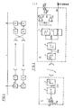
- the present invention relates generally to the transmission of information in differential protection systems such as that which is illustrated in FIG. 1.
- This figure represents a high voltage line L whose protection is ensured between points A and B.
- a and B are arranged measurement transformers, generically designated by M. a protection circuit P, a transmitter E and a receiver R.
- Measuring transformers M, at point A have the function of producing signals representative of the voltages and currents of line L at point A or any other information relevant for the protection of this line.
- This information is firstly transmitted directly to the protection circuit at point A, and secondly transmitted to the protection circuit P at point B via a transmitter E located at point A and a receiver located at point B.
- the protection circuits P located at each end receive relevant information relating to the end 'line where they are located and information on the other end of the line .
- protection circuits P can then, by comparing the information they receive from each of the ends of the line L, detect any faults affecting this line.
- the invention aims to detect transmission noise, with the aim of avoiding untimely operation of the protection circuits P.
- the transmitter E of FIG. 2 receives a signal S to be transmitted, representing information relevant for protection, such as the value of a line voltage or current, supplied by one of the transformers M.
- This signal S is, in a summing amplifier 1. added to a known and chosen bias voltage v o so that the output of this summing 1 keeps a constant sign and can thus directly control a voltage frequency converter 2.
- the output signal of the converter 2, which represents the modulated signal emitted SME, is delivered to a transmission circuit 3 which takes charge, by radio means for example, of sending this signal to the transmission circuit 4 of a receiver R.
- the received modulated signal, available at the output of circuit 4, is designated by SMR to remind the possibility that this signal differs from the emulated modulated signal SME .
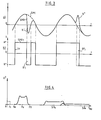
- FIG. 3a represents as a function of time t the amplitude V of the modulated signals emitted SME and received SMR, in the case where transmission noises with negative (B - ) or positive (B + ) contribution have distorted the signal emitted during of the transmission. It is noted in particular that the zero crossings of the SME and SMR signals are different.
- the receiver includes a bistable circuit 5 (Schmitt trigger) receiving the modulated signal received SMR and delivering a modulated signal formatted SMR 1 whose amplitude variations are limited to sharp transitions TF between two amplitude levels N + and N - equidistant from zero. If the signal SMR has a positive polarity, the signal formatted SMR 1 is at the positive level N + , and if the signal SMR has a polarity negative, the signal formatted SMR is at the negative level N.
- a bistable circuit 5 Schot trigger
- the modulated signal received and formatted SMR 1 is delivered to a demodulator 6 which produces at its output a reconstituted signal SR.
- Such demodulators are well known to those skilled in the art, so their detailed description is largely superfluous. They may consist, for example, of a frequency-voltage converter delivering a signal comprising DC and AC components and which, after elimination of its DC component, constitutes the demodulated signal SR.
- this reconstituted signal SR is a faithful image of the modulating signal S from which the modulated signal SME was produced, and can therefore be used by the protection circuit P.
- the signal formatted SMR 1 has a frequency spectrum of the type illustrated in FIG. 4.
- F o represents the frequency of the carrier wave, that is to say the frequency which is adopted by the modulated signal SME if the modulating signal S is zero, and which is due to the frequency conversion of the bias voltage V o .
- the signal S is a sinusoidal signal
- the frequency of the modulated signal emitted SME is of the form F o + KV (S) where K is a constant and where V (S) denotes the instantaneous value, positive or negative , of signal S: it follows that the frequency of the modulated signal emitted SME changes between a minimum frequency: and a maximum frequency: where
- Such a frequency characteristic is found, in FIG. 4, in the frequency spectrum of the signal formatted SMR 1 , which shows frequency components in an Fm-FM band centered on the frequency F 0 of the carrier wave .
- FIG. 4 also shows components in bands centered on the odd frequencies 3 F o , 5 F o , these components however being due solely to the shaping, by circuit 5, of the SMR signal directly received.
- the invention essentially rests on the demonstration and use of the fact that in the presence of impulsive transmission noises, the spectrum of the SMR signal 1 represented in FIG. 4 has frequency components of relatively large amplitude in a band between zero and the minimum frequency F m of the modulated signal transmitted, while in the absence of transmission noise this spectrum is free of low frequency components of significant amplitude, even if the modulated signal received SMR 1 is affected by irregularities revealing a line defect.
- the transmission noise are highlighted by means of a lowpass filter or bandpass Butterworth 5 th order, 7, receiving the modulated shaped signal S MR 1 .
- the filter 7 does not deliver any significant signal at its output, provided that the upper cutoff frequency F c of this filter is lower than the minimum frequency F.
- the filter 7 delivers an output signal, capable of being detected under satisfactory conditions, and corresponding to the impulse response of this filter.
- the filter 7 can directly receive the modulated signal received SMR, it is very advantageous to make sure that the filter 7 receives the modulated signal formatted SMR 1 .
- the bistable shaping circuit 5 therefore fulfills, when placed before the filter, 7, a function of normalizing the energy of the transmission noises leading to better detection of the latter.
- the upper cut-off frequency F c of this filter is preferably chosen to be less than half the minimum frequency F m , so that the residual signal delivered by this filter in the absence of noise has a very low level, for example less in absolute value than a threshold v 1 .
- the lower cutoff frequency of this filter is chosen close to zero, for example of the order of twenty hertz, so that the output of this filter can be activated significantly by detecting frequencies distributed over a band of fairly wide frequency.
- the impulse response of filter 7, indicating the presence of transmission noise, is for example detected by comparing, in two respective comparators 8a and 8b, the output signal of filter 7 with the positive threshold + V 1 and with the threshold negative -V 1 .
- comparators 8a and 8b are connected to the inputs of a NOR gate 9 which delivers a signal VAL (SR) for validation of the reconstituted signal SR, this validation signal being in logic state "1" in the absence of transmission noise detected, and in logic state "0" in the presence of noise.
- SR a signal VAL
- the signal VAL (SR) is, like the signal SR, transmitted to the protection circuit P and commands the circuit P not to take into account the signal SR at times when the latter is assumed to be affected by transmission noise.
- the different parameters entered can take the following values:
Landscapes
- Engineering & Computer Science (AREA)
- Power Engineering (AREA)
- Noise Elimination (AREA)
- Monitoring And Testing Of Transmission In General (AREA)
- Emergency Protection Circuit Devices (AREA)
Applications Claiming Priority (2)
| Application Number | Priority Date | Filing Date | Title |
|---|---|---|---|
| FR8509628A FR2583930B1 (fr) | 1985-06-25 | 1985-06-25 | Procede et dispositif de controle de la transmission de signaux de protection differentielle |
| FR8509628 | 1985-06-25 |
Publications (2)
| Publication Number | Publication Date |
|---|---|
| EP0210093A1 true EP0210093A1 (de) | 1987-01-28 |
| EP0210093B1 EP0210093B1 (de) | 1991-07-24 |
Family
ID=9320636
Family Applications (1)
| Application Number | Title | Priority Date | Filing Date |
|---|---|---|---|
| EP86401365A Expired - Lifetime EP0210093B1 (de) | 1985-06-25 | 1986-06-23 | Methode und Vorrichtung zur Überwachung der Übertragung von Signalen eines Differentialschutzes |
Country Status (5)
| Country | Link |
|---|---|
| US (1) | US4780908A (de) |
| EP (1) | EP0210093B1 (de) |
| JP (1) | JP2506338B2 (de) |
| DE (1) | DE3680409D1 (de) |
| FR (1) | FR2583930B1 (de) |
Families Citing this family (2)
| Publication number | Priority date | Publication date | Assignee | Title |
|---|---|---|---|---|
| US5793750A (en) * | 1995-10-20 | 1998-08-11 | Schweitzer Engineering Laboratories, Inc. | System of communicating output function status indications between two or more power system protective relays |
| CN100379110C (zh) * | 2003-11-06 | 2008-04-02 | 北京四方继保自动化有限公司 | 线路纵联差动保护的远方环回测试方法 |
Citations (2)
| Publication number | Priority date | Publication date | Assignee | Title |
|---|---|---|---|---|
| US3947636A (en) * | 1974-08-12 | 1976-03-30 | Edgar Albert D | Transient noise filter employing crosscorrelation to detect noise and autocorrelation to replace the noisey segment |
| US4203072A (en) * | 1978-05-15 | 1980-05-13 | Rockwell International Corporation | Reduction of impulse noise contribution to receiver squelch threshold |
Family Cites Families (4)
| Publication number | Priority date | Publication date | Assignee | Title |
|---|---|---|---|---|
| CA1202682A (en) * | 1982-01-26 | 1986-04-01 | Shinjiro Umetsu | Pager receiver comprising a memory storing a sequence of information signals to be tested |
| US4401860A (en) * | 1982-01-29 | 1983-08-30 | Bell Telephone Laboratories, Incorporated | Frequency signaling method and apparatus with dynamic compensation for frequency errors |
| US4524446A (en) * | 1982-07-13 | 1985-06-18 | Westinghouse Electric Corp. | Signal quality monitor for protective relay system |
| US4491968A (en) * | 1983-04-07 | 1985-01-01 | Comsonics, Inc. | Status monitor |
-
1985
- 1985-06-25 FR FR8509628A patent/FR2583930B1/fr not_active Expired - Fee Related
-
1986
- 1986-06-16 US US06/874,327 patent/US4780908A/en not_active Expired - Fee Related
- 1986-06-23 EP EP86401365A patent/EP0210093B1/de not_active Expired - Lifetime
- 1986-06-23 DE DE8686401365T patent/DE3680409D1/de not_active Expired - Fee Related
- 1986-06-24 JP JP61148001A patent/JP2506338B2/ja not_active Expired - Lifetime
Patent Citations (2)
| Publication number | Priority date | Publication date | Assignee | Title |
|---|---|---|---|---|
| US3947636A (en) * | 1974-08-12 | 1976-03-30 | Edgar Albert D | Transient noise filter employing crosscorrelation to detect noise and autocorrelation to replace the noisey segment |
| US4203072A (en) * | 1978-05-15 | 1980-05-13 | Rockwell International Corporation | Reduction of impulse noise contribution to receiver squelch threshold |
Non-Patent Citations (1)
| Title |
|---|
| IEEE TRANSACTIONS ON POWER APPARATUS AND SYSTEMS, vol. PAS-97, no. 6, novembre/décembre 1978, pages 2272-2280, IEEE, New York, US; M. KITAGAWA et al.: "Newly developed FM current-differential carrier relaying system and its field experiences" * |
Also Published As
| Publication number | Publication date |
|---|---|
| US4780908A (en) | 1988-10-25 |
| FR2583930A1 (fr) | 1986-12-26 |
| EP0210093B1 (de) | 1991-07-24 |
| JPS6244022A (ja) | 1987-02-26 |
| FR2583930B1 (fr) | 1994-02-25 |
| JP2506338B2 (ja) | 1996-06-12 |
| DE3680409D1 (de) | 1991-08-29 |
Similar Documents
| Publication | Publication Date | Title |
|---|---|---|
| EP0093651B1 (de) | Gegen Störsignale geschützter Mehrfachträgerempfänger | |
| US5825515A (en) | Supervisory apparatus for optical transmission system | |
| BE898477A (fr) | Système de transmission de signaux digitaux. | |
| EP0166839A1 (de) | Verfahren und Vorrichtung zur Messung des Phasen-Jitters eines Übertragungskanals | |
| EP0531047A2 (de) | Überwachung optischer Leitungen | |
| EP0433198B1 (de) | Amplitudenmodulation-Übertragungssystem mit unterdrücktem Träger, das die Polarität des übertragenen Signals erhält | |
| EP0113291B1 (de) | Verfahren und Einrichtung zur Sprachinterpolation in einem System zur Übertragung von digitalisierter Sprache | |
| EP0037317A1 (de) | Verfahren zur Demodulation eines amplitudemodulierten Signals, Demodulator zur Ausführung dieses Verfahrens und Fernsehsystem mit einem solchen Demodulator | |
| EP0099814B1 (de) | Für Funkverbindungen hoher Frequenz in gestörtem Umfeld ausgelegte Einrichtung zur Wiedergewinnung der Taktfrequenz | |
| EP0028857B1 (de) | Vorrichtung zur Trägererkennung in einem einen Echokompensator erhaltenden Modem | |
| EP0014505A1 (de) | System zum Prüfen einer mit einem Echo-Unterdrücker ausgerüsteten Vorrichtung | |
| EP0404002B1 (de) | Detektor für Niederfrequenz-Wechselstromsignale für eine Telefonverbindungsleitung | |
| EP0210093B1 (de) | Methode und Vorrichtung zur Überwachung der Übertragung von Signalen eines Differentialschutzes | |
| FR2497958A1 (fr) | Dispositif de determination de l'instant d'arrivee d'impulsions, utilisation dans un equipement de mesure de distances et equipement de mesure comportant un tel dispositif | |
| EP0097753B1 (de) | Tonempfänger für digitales Datenübertragungssystem | |
| EP0089276A1 (de) | Taktfrequenzwiedergewinnungseinrichtung für digitale Übertragung | |
| EP0412024A1 (de) | Vorrichtung zur Messung vom Effektivwert eines Signales, insbesondere zur Messung des Stromes in einem statischen Auslöser | |
| EP0432683B1 (de) | Demodulator mit phasenverkettetem Kreis | |
| FR2724512A1 (fr) | Dispositif d'identification d'une sequence predeterminee de signaux dans un modem | |
| EP0365401B1 (de) | Vergleichsschaltung mit variabler Hysterese für eine digitale Audio-Empfangsschnittstelle | |
| EP0065904B1 (de) | Zustandsermittlungsverfahren eines alles oder nichts modulierten Wechselsignales in gestörter Umgebung | |
| EP0184953B1 (de) | Verfahren und Vorrichtung zur digitalen Datenübertragung mittels Differenzfrequenzumtastung | |
| EP0404001B1 (de) | Signalisierungsdetektor für Gebührensignalisierung für eine Telefonverbindungsleitung | |
| EP0329049B1 (de) | Verfahren zur Regelung der Abtastzeitpunkte in einer digitalen Übertragung mit Quadraturträgermodulation und Einrichtung zur Durchführung des Verfahrens | |
| EP0031746A2 (de) | Schaltung zur Demodulation eines digital modulierten Signals und eine solche Schaltung enthaltender Empfänger |
Legal Events
| Date | Code | Title | Description |
|---|---|---|---|
| PUAI | Public reference made under article 153(3) epc to a published international application that has entered the european phase |
Free format text: ORIGINAL CODE: 0009012 |
|
| AK | Designated contracting states |
Kind code of ref document: A1 Designated state(s): CH DE GB IT LI SE |
|
| 17P | Request for examination filed |
Effective date: 19870218 |
|
| RAP1 | Party data changed (applicant data changed or rights of an application transferred) |
Owner name: SCHLUMBERGER INDUSTRIES |
|
| 17Q | First examination report despatched |
Effective date: 19900820 |
|
| GRAA | (expected) grant |
Free format text: ORIGINAL CODE: 0009210 |
|
| AK | Designated contracting states |
Kind code of ref document: B1 Designated state(s): CH DE GB IT LI SE |
|
| REF | Corresponds to: |
Ref document number: 3680409 Country of ref document: DE Date of ref document: 19910829 |
|
| GBT | Gb: translation of ep patent filed (gb section 77(6)(a)/1977) | ||
| ITF | It: translation for a ep patent filed | ||
| PLBE | No opposition filed within time limit |
Free format text: ORIGINAL CODE: 0009261 |
|
| STAA | Information on the status of an ep patent application or granted ep patent |
Free format text: STATUS: NO OPPOSITION FILED WITHIN TIME LIMIT |
|
| 26N | No opposition filed | ||
| EAL | Se: european patent in force in sweden |
Ref document number: 86401365.1 |
|
| PGFP | Annual fee paid to national office [announced via postgrant information from national office to epo] |
Ref country code: GB Payment date: 19990511 Year of fee payment: 14 |
|
| PGFP | Annual fee paid to national office [announced via postgrant information from national office to epo] |
Ref country code: CH Payment date: 19990514 Year of fee payment: 14 |
|
| PGFP | Annual fee paid to national office [announced via postgrant information from national office to epo] |
Ref country code: SE Payment date: 19990525 Year of fee payment: 14 Ref country code: DE Payment date: 19990525 Year of fee payment: 14 |
|
| PG25 | Lapsed in a contracting state [announced via postgrant information from national office to epo] |
Ref country code: GB Free format text: LAPSE BECAUSE OF NON-PAYMENT OF DUE FEES Effective date: 20000623 |
|
| PG25 | Lapsed in a contracting state [announced via postgrant information from national office to epo] |
Ref country code: SE Free format text: LAPSE BECAUSE OF NON-PAYMENT OF DUE FEES Effective date: 20000624 |
|
| PG25 | Lapsed in a contracting state [announced via postgrant information from national office to epo] |
Ref country code: LI Free format text: LAPSE BECAUSE OF NON-PAYMENT OF DUE FEES Effective date: 20000630 Ref country code: CH Free format text: LAPSE BECAUSE OF NON-PAYMENT OF DUE FEES Effective date: 20000630 |
|
| GBPC | Gb: european patent ceased through non-payment of renewal fee |
Effective date: 20000623 |
|
| REG | Reference to a national code |
Ref country code: CH Ref legal event code: PL |
|
| EUG | Se: european patent has lapsed |
Ref document number: 86401365.1 |
|
| PG25 | Lapsed in a contracting state [announced via postgrant information from national office to epo] |
Ref country code: DE Free format text: LAPSE BECAUSE OF NON-PAYMENT OF DUE FEES Effective date: 20010403 |
|
| PG25 | Lapsed in a contracting state [announced via postgrant information from national office to epo] |
Ref country code: IT Free format text: LAPSE BECAUSE OF NON-PAYMENT OF DUE FEES Effective date: 20050623 |