EP0210274B1 - VORRICHTUNG FüR EINE INFORMATIONSTAFEL - Google Patents
VORRICHTUNG FüR EINE INFORMATIONSTAFEL Download PDFInfo
- Publication number
- EP0210274B1 EP0210274B1 EP85900756A EP85900756A EP0210274B1 EP 0210274 B1 EP0210274 B1 EP 0210274B1 EP 85900756 A EP85900756 A EP 85900756A EP 85900756 A EP85900756 A EP 85900756A EP 0210274 B1 EP0210274 B1 EP 0210274B1
- Authority
- EP
- European Patent Office
- Prior art keywords
- light emitting
- display
- emitting devices
- lamp case
- multicolored
- Prior art date
- Legal status (The legal status is an assumption and is not a legal conclusion. Google has not performed a legal analysis and makes no representation as to the accuracy of the status listed.)
- Expired - Lifetime
Links
Images





Classifications
-
- G—PHYSICS
- G09—EDUCATION; CRYPTOGRAPHY; DISPLAY; ADVERTISING; SEALS
- G09F—DISPLAYING; ADVERTISING; SIGNS; LABELS OR NAME-PLATES; SEALS
- G09F9/00—Indicating arrangements for variable information in which the information is built-up on a support by selection or combination of individual elements
- G09F9/30—Indicating arrangements for variable information in which the information is built-up on a support by selection or combination of individual elements in which the desired character or characters are formed by combining individual elements
-
- G—PHYSICS
- G09—EDUCATION; CRYPTOGRAPHY; DISPLAY; ADVERTISING; SEALS
- G09F—DISPLAYING; ADVERTISING; SIGNS; LABELS OR NAME-PLATES; SEALS
- G09F9/00—Indicating arrangements for variable information in which the information is built-up on a support by selection or combination of individual elements
- G09F9/30—Indicating arrangements for variable information in which the information is built-up on a support by selection or combination of individual elements in which the desired character or characters are formed by combining individual elements
- G09F9/33—Indicating arrangements for variable information in which the information is built-up on a support by selection or combination of individual elements in which the desired character or characters are formed by combining individual elements being semiconductor devices, e.g. diodes
-
- G—PHYSICS
- G09—EDUCATION; CRYPTOGRAPHY; DISPLAY; ADVERTISING; SEALS
- G09F—DISPLAYING; ADVERTISING; SIGNS; LABELS OR NAME-PLATES; SEALS
- G09F13/00—Illuminated signs; Luminous advertising
- G09F13/04—Signs, boards or panels, illuminated from behind the insignia
- G09F13/0418—Constructional details
- G09F13/0472—Traffic signs
Definitions
- This invention relates to an information display apparatus which uses a large number of multicolored light emitting devices as display elements to enhance visibility, visual attractivity, and attention evocativeness.
- So far information display boards have been proposed that are constructed to show specific display patterns by lighting many groups of light emitting devices, such as electric bulbs or light emitting diodes (LEDs), which are arranged in the checkerboard pattern to form specific display patterns.
- light emitting devices such as electric bulbs or light emitting diodes (LEDs)
- the "multicolored light emitting device” represents a light emitting device in combination of one or more LEDs of different colors, such as red, yellow and blue, arranged on a substrate, connected with wires and fixed to a base shell having pins or a metal base to form a single device that can emit one color, or more colors simultaneously as required, and change the color to be emitted.
- a display apparatus with light emitting devices (1) which are arrayed in a checkered pattern layout merely by providing three fluorescent lamps in one case and covering the front face of said case with a dispersion plate.
- a display apparatus is provided with light emitting devices which are made up by a plurality of bulbs stored in cases and arrayed in a matrix pattern.
- the bulbs are set in the cases so that the same type of bulbs are arranged at a position to entirely display a specific display pattern and are only enabled to form a plurality of display patterns with one light emitting device by turning on and off the bulbs. Therefore, this known apparatus has an extremely complicated construction for which a plurality of bulbs corresponding to required display patterns should be designed and used in each light emitting device and the positions of bulbs in each light emitting device differ with from other light emitting devices to display different display patterns with the same light emitting device.
- DE-C-33 13 353 also discloses a display apparatus which is constructed so that bulbs are accommodated in frames partitioned in a matrix pattern.
- this reference does also not disclose the multicolored light emitting devices in accordance with the present invention and comparison with such a light emitting device rather clarifies that the multicolored light emitting devices are based on an extremely unique construction.
- this invention improves the above-mentioned device so that many devices can be arranged in a checkerboard pattern as a display unit of information board. That is, if plural LEDs of different colors are merely arrayed in groups and fixed on substrates in such structure that the LED groups are only fixed with base shell after wiring connection of them, the LED groups heat up during use and, the temperature rise lowers brightness of the LEDs and particularly shortens the life of LEDs, thus causing a breakdown of multicolored light emitting devices and also of the information display board. Furthermore, these multicolored light emitting devices require dust- and water-proof properties for outdoor use.
- the purpose of this invention is, in view of the above-mentioned disadvantages of the prior art, to provide an information display apparatus that maintains a high level of visibility, visual attractivity and attention evocativeness by lighting specific display patterns, as needed, in a display unit in which many light emitting devices as display elements are arrayed in a checkerboard pattern, while changing the brightness of the patterns and flickering them, and also by changing the lighting colors of the patterns.
- Another purpose of this invention is to provide an information display apparatus having a display unit in which multicolored light emitting devices, composed of many light emitting diodes contained in lamp cases in the structure that can dissipate heat from leads of devices whose temperature is liable to excessively rise, are arrayed in a checkerboard pattern, thus enabling effective dissipation of hot air in the lamp cases.
- Another purpose of this invention is to provide an information display apparatus that can serve efficiently for out door use by making the exposed part on the front of multicolored light emitting devices dust- and water-proof.
- An information display apparatus in accordance with the present invention is provided with a display unit that comprises many multicolored light emitting devices arrayed in a checkerboard pattern over the whole area of the opening of the front flame constructing the main body of the information display apparatus.
- Multicolored light emitting devices have such structure that when they are arrayed in a checkerboard pattern in a display unit, heat dissipation holes formed in the side plates of the lamp cases along leads of LEDs whose temperature is liable to rise are alinged in vertical and horizontal directions and provide air paths that can circulate air in the display.
- a transparent cover is mounted on the front of each lamp case, that is, on the light emitting side of LEDs, to provide the dust- and water-proof properties to the lamp case to prevent dust and water intrusion from the outside of the apparatus.
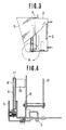
- the main body of an information display apparatus 1 is composed of an enclosure 2 and a front frame 5 which is fitted to the bottom edge of enclosure 2 by means of hinge 3 so as to turn freely but usually fixed with clamps 4 to the top edge of the front opening of enclosure 2.
- the front flame 5 of main body 1 is fitted with a display board 6, and a hood 7 which interrupts rays of light from incidence on a display board 6 beyond the circumference of the board, especially from the upper side and both the right and left sides of the enclosure.
- the display board 6 is provided with many shading windows 8 which are arrayed in a checkerboard pattern over the whole face of the displayboard 6, and behind the shading windows 8 in main body 1, sockets or a base board 9 is arranged and many multicolored light emitting devices 10 are installed on this socket or base board 9 so that light emitting parts of multicolored light emitting devices 10 come to the same positions with shading windows 8.
- a transparent plate 11 for dust- and water-proofing can be arranged between the back face of display board 6 and the light emitting part of multicolored light emitting devices 10, which are energized to flicker by a printed circuit board 12 for the energization.
- multicolored light emitting devices 10 have respectively such structure that LEDs 14, two or more for each of different colors, are arrayed and fixed on the surface of a substrate 15 and wired on the back face of substrate 15, which is provided with a specific number of electrodes 16 projecting out of the substrate.
- diodes 14 of two different colors are used and arranged alternatively by color in groups of the square form in which two or more LEDs of each color are arrayed in every line.
- the number of LEDs 14, kinds of lighting color, combination of colors, etc. can be arbitrarily selected and changed in response to the purpose of using the information display board composed of the multicolored light emitting devices 10 but not limited to the above.
- a lamp case 17 is fitted to construct a multicolored light emitting device 10.
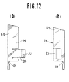
- the lamp case 17 is provided with heat dissipation holes 18 in the side plates of the lead section 13 of lamp case in which leads of the LEDs 14 are contained, so that when many multicolored light emitting devices 10 are arrayed in a checkerboard pattern to construct a display unit of the information display apparatus, the heat dissipation holes 18 of the light emitting devices 10 arrayed in a line can communicate with the adjacent hole.
- the lamp case 17 is composed of two side plates 17a and 17b that form a cross section in the shape of " ", and these side plates 17a and 17b are combined to form a square lamp case. Namely, side plates 17a and 17b are respectively provided with the above-mentioned heat dissipation hole 18 in the side plate which is not devided and with a groove 19 at the bottom of the side plate so that an edge of a substrate 15 can be fitted to the groove 19.
- one divided part 17a has a hooking tongue 20 at the edge of its divided face and another divided part 17b a hooking edge 21, which catches the hooking tongue 20.
- the above-mentioned hooking tongue 20 is fitted to hooking edge 21 while making both divided faces come to close contact from the right and left, and a hook 20 provided at the edge of hooking tongue 20 is engaged with the end part of hooking edge 21.
- hook 22 is separated from the end part of hooking edge 21 by pushing hooking tongue 20 to the outside of side plate 17a, and thus side plates 17a and 17b can be parted.
- a guide piece 23 is fixed to either of divided side-plate parts 17a and 17b and a guide groove 24 is cut on other side of the divided side-plate parts 17a and 17b and fitted to the above-mentioned guide piece 23.
- the lamp case 17 may be constructed in a shape of cylinder.
- a group of plural LEDs 14 is inserted into a lamp case 17 from the rear end of the case, and the edge of the substrate 15 is fitted to the groove 19 of the lamp case 17, while widening the rear edge of lamp case.
- Heat dissipation holes 18 may be formed in all the side plates of the lamp case 17 so that the high-temperature air generated by leads 13 of LEDs 14 can flow in the horizontal direction as well.
- an opaque plate or filter for adjusting the lighting color of each LED group, or a lens (not illusrated) for enlarging the visible area of the LED group may be installed in the front opening of the lamp case.
- the lamp case 17 has a function as hood at the same time.
- the LEDs which constitute a multicolored light emitting device 10 When the LEDs which constitute a multicolored light emitting device 10 receive irradiation of external light, it is liable to halation, depending on the irradiating direction, and if they are energized in such condition, the external light reduces the visibility of them remarkaly. Generally, although the external light is shaded by the shading windows 8 of the display board 9, it can be also prevented also by making the edges of lamp case 17 project forward from the LED group 14. The length of the projection of the edge of lampcase 17 should be decided definitely according to the condition to use multicolored light emitting devices 10. However, generally the projection in the direction of irradiating external light is enough in the length of 10 to 15 mm.
- Using the multicolored light emitting device 10 of such structure permits change of the shading windows 8 of display board 9 to a single display window.
- Such information as characters, figures and marks which should be displayed on the display board 6, for example, such information as "warning declared' as shown in Fig. 17 is displayed by selecting one or more display patterns from several display patterns stored previously in semiconductor storage devices of control unit (not illustrated), sending out the control, signal according to the selected display pattern(s) to the display unit, lighting the multicolored light emitting devices corresponding to the display pattern(s) from all the multicolored light emitting devices 10, and controlling or flickering the light of the devices.
- control unit can be contained in eclosure 2 of the main body 1 together with other electrical devices, and if desired, the control unit can be arranged outside the enclosure 2.
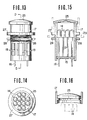
- Figs. 13 to 15 show another embodiment concerning multicolored light emitting devices in which transparent cover 25 covers the front opening of lampcase 17 in order to provide dust- and water-proof properties to the lampcase 17 and enhance the adaptability of the lamp case to outdoor installation.
- lamp case 17 is constructed in the cylindrical form and six heat dissipation holes 18 are provided along the circumference of the lampcase, but the numbers of the holes are not limited to six.
- a flange 27 is fitted, and a nut 28 is a set to the threads 26.
- the flange 27 and nut 28 are used for holding, in the mounting plate 29, multicolored light emitting devices 10 arrayed and fitted in the display unit, and each multicolored light emitting device 10 can be removed freely from the mounting plate 29 by loosening the nut 28.
- the structure for holding the light emitting devices in the mounting plate 29 is not limited to the combination of screw 26 and nut 28 as mentioned above.
- Fig. 16 shows a modified example of above-mentioned embodiment related to the front opening of lampcase 17, and the edge of the opening is projected a little forward from cover 20 can prevent the lighting face of cover 25 from exposure to direct sunlight or other external light that reduces contrast between the light from the lighting face and external light and therefore also lowers the visibility of the information display of information display apparatus.
- Such purpose can be usually achieved enough by 10-15 mm forward projection of cover 25.
- the visibility, visual attractivity and attention evocativeness of the information display apparatus can be enhanced by displaying in the desired brightness the specific display patterns selected from predetermined display patterns in response to the road information in the area where the information display apparatus of the present invention is installed.
- the high-temperature air generated in the lamp case is vented out through heat dissipation holes, temperature rise in the lamp case is controlled, and thus reduction of brightness of LEDs by high temperature can be prevented.
- adaptability of the information display apparatus to outdoor installation can be improved by selecting the multicolored light emitting devices which excels in dust- and water-proof properties.
- the information display apparatus according to the present invention is suitable for application as road traffic information display apparatus installed outdoors and for other information display purposes.
Landscapes
- Physics & Mathematics (AREA)
- General Physics & Mathematics (AREA)
- Engineering & Computer Science (AREA)
- Theoretical Computer Science (AREA)
- Illuminated Signs And Luminous Advertising (AREA)
- Devices For Indicating Variable Information By Combining Individual Elements (AREA)
Claims (4)
- Informationsanzeigevorrichtung, die geeignet ist, diejenigen Gruppen von vielfarbigen lichtemittierenden Einrichtungen (10) zu erleuchten oder flackern zu lassen, die spezifizierten Anzeigemustern entsprechend, die vorher in einer Halbleiterspeichereinrichtung einer Kontrolleinheit gespeichert sind, und die aus einer großen Zahl von vielfarbigen lichtemittierenden Einrichtungen, die in einer Matrixform angeordnet sind, um eine Anzeigeeinheit durch eine Schalteinheit zu bilden, um spezielle Informationen mit Zeichnungen, Symbolen, Buchstabengruppen, etc., darzustellen, dadurch gekennzeichnet, daß die vielfarbigen lichtemittierenden Einrichtungen (10), die die Anzeigeeinheit bilden, derart ausgebildet sind, daß ein Substrat (15) mit einer mehrfachen Anzahl von Arten von einer oder einer Vielzahl von lichtemittierenden Dioden (14) für verschiedene lichtemittierende Farben ausgestattet ist, die eine spezifizierte Länge von Leitungen (13) an ihrer oder ihren oberen Oberflächen und eine Elektrode (16) an ihrer oder ihren hinteren Oberflächen und ein Lampengehäuse (17), welches das Substrat (15) hält, um frei wieder aufsetzbar zu sein, und das die lichtemittierenden Dioden (14) aufnimmt, daß eine Seitenplatte des Lampengehäuses (17) mit Hitzeabzugslöchern (18) versehen ist, welche horizontal und vertikal miteinander in Verbindung stehen, in einer Position, in der die Leitungen (13) der lichtemittierenden Dioden (14) angeordnet sind und in der eine Öffnungskante des Lampengehäuses (17) auf der Seite der Einfallsrichtung der lichtemittierenden Dioden (14) über die Front der lichtemittierenden Dioden (14) vorsteht, wobei die Kontrolleinheit geeignet ist, ein gewünschtes Anzeigemuster zu bilden, in dem ein oder mehrere gewünschte Anzeigemuster aus Anzeigemustern, die vorher in der Halbleiterspeichereinrichtung gespeichert wurden, auswählt, und Kontrollsignale aus zur Anzeigeeinheit aussendet, die das ausgewählte und gebildete Anzeigemuster betreffen, und das die Schalteinheit geeignet ist, um die Gruppen von vielfarbigen lichtemittierenden Einrichtungen zu erleuchten, flackern zu lassen oder in ihrer Helligkeit zu adjustieren, welche zu einem Muster, das von der Kontrolleinheit ausgewählt und gebildet wird, gehören, und die Farben des Lichts, das von diesen Gruppen von vielfarbigen lichtemittierenden Einrichtungen emittiert wird, wie gewünscht zu schalten.
- Informationsanzeigevorrichtung nach Anspruch 1, dadurch gekennzeichnet, daß eine Abdeckung (25) für eine vorderseitige Öffnung des Lampengehäuses (17) angepaßt ist.
- Informationsanzeigevorrichtung nach Anspruch 2, dadurch gekennzeichnet, daß die Abdeckung (25) eine transparente Platte, eine opaque Platte oder ein gefärbter Filter ist.
- Informationsanzeigevorrichtung nach Anspruch 2, dadurch gekennzeichnet, daß die Abdeckung (25) eine Linsenfunktion bereitstellt.
Priority Applications (2)
| Application Number | Priority Date | Filing Date | Title |
|---|---|---|---|
| DE19853587585 DE3587585T2 (de) | 1985-01-26 | 1985-01-26 | VORRICHTUNG FüR EINE INFORMATIONSTAFEL. |
| AT85900756T ATE94673T1 (de) | 1985-01-26 | 1985-01-26 | Vorrichtung fuer eine informationstafel. |
Applications Claiming Priority (1)
| Application Number | Priority Date | Filing Date | Title |
|---|---|---|---|
| PCT/JP1985/000034 WO1986004439A1 (fr) | 1985-01-26 | 1985-01-26 | Panneau d'affichage d'informations |
Publications (3)
| Publication Number | Publication Date |
|---|---|
| EP0210274A1 EP0210274A1 (de) | 1987-02-04 |
| EP0210274A4 EP0210274A4 (de) | 1989-04-27 |
| EP0210274B1 true EP0210274B1 (de) | 1993-09-15 |
Family
ID=13846352
Family Applications (1)
| Application Number | Title | Priority Date | Filing Date |
|---|---|---|---|
| EP85900756A Expired - Lifetime EP0210274B1 (de) | 1985-01-26 | 1985-01-26 | VORRICHTUNG FüR EINE INFORMATIONSTAFEL |
Country Status (3)
| Country | Link |
|---|---|
| EP (1) | EP0210274B1 (de) |
| KR (1) | KR890005294B1 (de) |
| WO (1) | WO1986004439A1 (de) |
Cited By (1)
| Publication number | Priority date | Publication date | Assignee | Title |
|---|---|---|---|---|
| GB2408135A (en) * | 2003-11-14 | 2005-05-18 | Box Consultants Ltd | Modular display system |
Families Citing this family (14)
| Publication number | Priority date | Publication date | Assignee | Title |
|---|---|---|---|---|
| US4852674A (en) * | 1987-07-30 | 1989-08-01 | Caterpillar Inc. | Method for displaying load distribution by monitoring a work vehicle suspension |
| JP2709316B2 (ja) * | 1987-07-30 | 1998-02-04 | キャタピラー インコーポレーテッド | ペイロード表示装置 |
| US5268828A (en) * | 1991-04-19 | 1993-12-07 | Takiron Co., Ltd. | Illuminant display device |
| JP2810562B2 (ja) * | 1991-07-10 | 1998-10-15 | ローム株式会社 | 発光ダイオ−ド表示器及び表示パネル |
| JP2818984B2 (ja) * | 1992-03-04 | 1998-10-30 | 株式会社 ケー・シー・シー・商会 | モザイク式パネル用照光表示装置 |
| US5450301A (en) * | 1993-10-05 | 1995-09-12 | Trans-Lux Corporation | Large scale display using leds |
| US5410328A (en) * | 1994-03-28 | 1995-04-25 | Trans-Lux Corporation | Replaceable intelligent pixel module for large-scale LED displays |
| FR2759476B1 (fr) * | 1997-02-11 | 1999-05-21 | Signature Sa | Sous-ensemble d'affichage lumineux et ecran d'affichage lumineux constitue par juxtaposition de tels sous-ensembles |
| GB2366900B (en) * | 2000-09-13 | 2004-12-29 | Box Consultants Ltd | A display element |
| JP4083659B2 (ja) | 2002-10-10 | 2008-04-30 | バルコ・ナムローゼ・フエンノートシャップ | パネルディスプレイおよびタイルドディスプレイ |
| EP1408475A1 (de) * | 2002-10-11 | 2004-04-14 | Barco N.V. | Licht emittierende Bildschirmanordnungen |
| EP1408476B1 (de) * | 2002-10-10 | 2014-10-15 | Barco N.V. | Lumineszente Displayanordnungen |
| ES2253058B1 (es) * | 2004-02-19 | 2006-12-16 | Odeco Electronica, S.A. | Mejoras introducidas en pantallas luminosas. |
| GB0716230D0 (en) * | 2007-08-21 | 2007-09-26 | Barco Nv | LED assembly |
Family Cites Families (18)
| Publication number | Priority date | Publication date | Assignee | Title |
|---|---|---|---|---|
| BE432729A (de) * | ||||
| GB1084523A (en) * | 1964-11-16 | 1967-09-27 | Ferranti Ltd | Improvements relating to means for viewing a display presented on or behind a partially reflecting surface |
| JPS4824541Y1 (de) * | 1968-05-14 | 1973-07-17 | ||
| JPS4827675Y1 (de) * | 1969-06-14 | 1973-08-15 | ||
| JPS5019381U (de) * | 1973-06-18 | 1975-03-04 | ||
| JPS5415585Y2 (de) * | 1973-12-05 | 1979-06-22 | ||
| US4197527A (en) * | 1975-05-09 | 1980-04-08 | Romney Russell H | Comprehensive information display system |
| JPS5616634Y2 (de) * | 1976-07-12 | 1981-04-17 | ||
| JPS5634494Y2 (de) * | 1976-12-03 | 1981-08-14 | ||
| JPS5491086U (de) * | 1977-12-08 | 1979-06-27 | ||
| JPS6134540Y2 (de) * | 1978-04-25 | 1986-10-07 | ||
| JPS5741669U (de) * | 1980-08-21 | 1982-03-06 | ||
| JPS5793983U (de) * | 1980-11-26 | 1982-06-09 | ||
| JPS57133081U (de) * | 1981-02-14 | 1982-08-19 | ||
| JPS57186055U (de) * | 1981-05-21 | 1982-11-26 | ||
| JPS5941385U (ja) * | 1982-09-08 | 1984-03-16 | 株式会社日本弘報教会 | 電光表示装置 |
| JPS59180582A (ja) * | 1983-03-31 | 1984-10-13 | 株式会社東芝 | 光半導体表示装置 |
| FR2574206B1 (fr) * | 1984-12-05 | 1987-09-04 | Delcourt Michel | Cellule emettrice de lumiere, de luminance et de chromatismes variables et ecran obtenu par la juxtaposition d'une pluralite de cellules emettrices |
-
1985
- 1985-01-26 KR KR1019860700396A patent/KR890005294B1/ko not_active Expired
- 1985-01-26 EP EP85900756A patent/EP0210274B1/de not_active Expired - Lifetime
- 1985-01-26 WO PCT/JP1985/000034 patent/WO1986004439A1/ja not_active Ceased
Cited By (2)
| Publication number | Priority date | Publication date | Assignee | Title |
|---|---|---|---|---|
| GB2408135A (en) * | 2003-11-14 | 2005-05-18 | Box Consultants Ltd | Modular display system |
| GB2408135B (en) * | 2003-11-14 | 2007-03-28 | Box Consultants Ltd | Modular display system |
Also Published As
| Publication number | Publication date |
|---|---|
| WO1986004439A1 (fr) | 1986-07-31 |
| KR860700368A (ko) | 1986-10-06 |
| EP0210274A4 (de) | 1989-04-27 |
| KR890005294B1 (ko) | 1989-12-20 |
| EP0210274A1 (de) | 1987-02-04 |
Similar Documents
| Publication | Publication Date | Title |
|---|---|---|
| EP0509522B1 (de) | Leuchtanzeigevorrichtung | |
| EP0210274A1 (de) | VORRICHTUNG FüR EINE INFORMATIONSTAFEL | |
| US5450301A (en) | Large scale display using leds | |
| US5697175A (en) | Low power drain illuminated sign | |
| US5036248A (en) | Light emitting diode clusters for display signs | |
| US5539623A (en) | Lighting device used in an exit sign | |
| US4954822A (en) | Traffic signal using light-emitting diodes | |
| US4271408A (en) | Colored-light emitting display | |
| US7468677B2 (en) | End cap warning signal assembly | |
| US5924785A (en) | Light source arrangement | |
| US5608290A (en) | LED flashing lantern | |
| US20030193816A1 (en) | Allochromatic light emitter | |
| US5715619A (en) | Information display sign | |
| CA2653899C (en) | Light bar | |
| GB2139340A (en) | Light for motor vehicles | |
| KR20040064245A (ko) | 발광유니트(Unit) | |
| CN118339403A (zh) | 机动车辆的包括发光元件矩阵的照明设备 | |
| EP0390479A2 (de) | Leuchtdioden-Gruppen für Anzeigesignalgeber | |
| US5448843A (en) | Low power drain illuminated sign | |
| JPH0439235B2 (de) | ||
| KR20200002171U (ko) | 면조명 구현이 가능한 선형 조명장치 | |
| US6234647B1 (en) | Full color parapet lamp for road or bridge | |
| JPH08125229A (ja) | 集合型ランプ | |
| CN211780790U (zh) | 一种可旋转带控制的高投光灯 | |
| WO1998002855A9 (en) | Led signal lamp assembly with multi-color capabilities |
Legal Events
| Date | Code | Title | Description |
|---|---|---|---|
| PUAI | Public reference made under article 153(3) epc to a published international application that has entered the european phase |
Free format text: ORIGINAL CODE: 0009012 |
|
| 17P | Request for examination filed |
Effective date: 19860619 |
|
| AK | Designated contracting states |
Kind code of ref document: A1 Designated state(s): AT BE CH DE FR GB LI LU NL SE |
|
| A4 | Supplementary search report drawn up and despatched |
Effective date: 19890427 |
|
| 17Q | First examination report despatched |
Effective date: 19910704 |
|
| RAP3 | Party data changed (applicant data changed or rights of an application transferred) |
Owner name: STANLEY ELECTRIC CO., LTD. Owner name: KOITO INDUSTRIES, LTD. Owner name: JAPAN TRAFFIC MANAGEMENT TECHNOLOGY ASSOCIATION |
|
| GRAA | (expected) grant |
Free format text: ORIGINAL CODE: 0009210 |
|
| AK | Designated contracting states |
Kind code of ref document: B1 Designated state(s): AT BE CH DE FR GB LI LU NL SE |
|
| PG25 | Lapsed in a contracting state [announced via postgrant information from national office to epo] |
Ref country code: SE Effective date: 19930915 Ref country code: LI Effective date: 19930915 Ref country code: CH Effective date: 19930915 Ref country code: BE Effective date: 19930915 Ref country code: AT Effective date: 19930915 |
|
| REF | Corresponds to: |
Ref document number: 94673 Country of ref document: AT Date of ref document: 19931015 Kind code of ref document: T |
|
| REF | Corresponds to: |
Ref document number: 3587585 Country of ref document: DE Date of ref document: 19931021 |
|
| ET | Fr: translation filed | ||
| REG | Reference to a national code |
Ref country code: CH Ref legal event code: PL |
|
| PG25 | Lapsed in a contracting state [announced via postgrant information from national office to epo] |
Ref country code: LU Free format text: LAPSE BECAUSE OF NON-PAYMENT OF DUE FEES Effective date: 19940131 |
|
| PLBE | No opposition filed within time limit |
Free format text: ORIGINAL CODE: 0009261 |
|
| STAA | Information on the status of an ep patent application or granted ep patent |
Free format text: STATUS: NO OPPOSITION FILED WITHIN TIME LIMIT |
|
| 26N | No opposition filed | ||
| REG | Reference to a national code |
Ref country code: GB Ref legal event code: IF02 |
|
| PGFP | Annual fee paid to national office [announced via postgrant information from national office to epo] |
Ref country code: GB Payment date: 20030102 Year of fee payment: 19 |
|
| PGFP | Annual fee paid to national office [announced via postgrant information from national office to epo] |
Ref country code: NL Payment date: 20030120 Year of fee payment: 19 Ref country code: FR Payment date: 20030120 Year of fee payment: 19 |
|
| PGFP | Annual fee paid to national office [announced via postgrant information from national office to epo] |
Ref country code: DE Payment date: 20030326 Year of fee payment: 19 |
|
| PG25 | Lapsed in a contracting state [announced via postgrant information from national office to epo] |
Ref country code: GB Free format text: LAPSE BECAUSE OF NON-PAYMENT OF DUE FEES Effective date: 20040126 |
|
| PG25 | Lapsed in a contracting state [announced via postgrant information from national office to epo] |
Ref country code: NL Free format text: LAPSE BECAUSE OF NON-PAYMENT OF DUE FEES Effective date: 20040801 |
|
| PG25 | Lapsed in a contracting state [announced via postgrant information from national office to epo] |
Ref country code: DE Free format text: LAPSE BECAUSE OF NON-PAYMENT OF DUE FEES Effective date: 20040803 |
|
| GBPC | Gb: european patent ceased through non-payment of renewal fee |
Effective date: 20040126 |
|
| PG25 | Lapsed in a contracting state [announced via postgrant information from national office to epo] |
Ref country code: FR Free format text: LAPSE BECAUSE OF NON-PAYMENT OF DUE FEES Effective date: 20040930 |
|
| NLV4 | Nl: lapsed or anulled due to non-payment of the annual fee |
Effective date: 20040801 |
|
| REG | Reference to a national code |
Ref country code: FR Ref legal event code: ST |