EP0210355B1 - Distributeur pour produits pâteux - Google Patents
Distributeur pour produits pâteux Download PDFInfo
- Publication number
- EP0210355B1 EP0210355B1 EP86106569A EP86106569A EP0210355B1 EP 0210355 B1 EP0210355 B1 EP 0210355B1 EP 86106569 A EP86106569 A EP 86106569A EP 86106569 A EP86106569 A EP 86106569A EP 0210355 B1 EP0210355 B1 EP 0210355B1
- Authority
- EP
- European Patent Office
- Prior art keywords
- piston
- dispenser
- membrane
- housing
- piston rod
- Prior art date
- Legal status (The legal status is an assumption and is not a legal conclusion. Google has not performed a legal analysis and makes no representation as to the accuracy of the status listed.)
- Expired
Links
- 235000014594 pastries Nutrition 0.000 title 1
- 239000012528 membrane Substances 0.000 claims abstract description 21
- 235000011837 pasties Nutrition 0.000 claims description 5
- 239000000463 material Substances 0.000 claims description 3
- 230000000149 penetrating effect Effects 0.000 claims 1
- 239000000126 substance Substances 0.000 abstract 1
- 238000007789 sealing Methods 0.000 description 5
- 239000010408 film Substances 0.000 description 3
- 238000009434 installation Methods 0.000 description 3
- 239000011324 bead Substances 0.000 description 2
- 230000015572 biosynthetic process Effects 0.000 description 2
- 230000008878 coupling Effects 0.000 description 2
- 238000010168 coupling process Methods 0.000 description 2
- 238000005859 coupling reaction Methods 0.000 description 2
- 238000011161 development Methods 0.000 description 2
- 230000018109 developmental process Effects 0.000 description 2
- 230000002093 peripheral effect Effects 0.000 description 2
- 235000001674 Agaricus brunnescens Nutrition 0.000 description 1
- 229910000639 Spring steel Inorganic materials 0.000 description 1
- 238000004026 adhesive bonding Methods 0.000 description 1
- 210000003323 beak Anatomy 0.000 description 1
- 230000000903 blocking effect Effects 0.000 description 1
- 230000006378 damage Effects 0.000 description 1
- 230000018044 dehydration Effects 0.000 description 1
- 238000006297 dehydration reaction Methods 0.000 description 1
- 230000000881 depressing effect Effects 0.000 description 1
- 238000001035 drying Methods 0.000 description 1
- 230000035515 penetration Effects 0.000 description 1
- 239000002243 precursor Substances 0.000 description 1
- 230000001681 protective effect Effects 0.000 description 1
- 239000010409 thin film Substances 0.000 description 1
Images
Classifications
-
- B—PERFORMING OPERATIONS; TRANSPORTING
- B65—CONVEYING; PACKING; STORING; HANDLING THIN OR FILAMENTARY MATERIAL
- B65D—CONTAINERS FOR STORAGE OR TRANSPORT OF ARTICLES OR MATERIALS, e.g. BAGS, BARRELS, BOTTLES, BOXES, CANS, CARTONS, CRATES, DRUMS, JARS, TANKS, HOPPERS, FORWARDING CONTAINERS; ACCESSORIES, CLOSURES, OR FITTINGS THEREFOR; PACKAGING ELEMENTS; PACKAGES
- B65D83/00—Containers or packages with special means for dispensing contents
- B65D83/76—Containers or packages with special means for dispensing contents for dispensing fluent contents by means of a piston
- B65D83/763—Containers or packages with special means for dispensing contents for dispensing fluent contents by means of a piston the piston being actuated by a reciprocating axial motion of a shaft which engages the piston, e.g. using a ratchet mechanism
Definitions
- the invention relates to a dispenser for pasty masses (M), with a piston (2) which is displaceably arranged in the dispenser housing (1) and moves in the opposite direction when the dispenser is emptied, and which is blocked in the opposite direction, and a pushbutton actuating surface which is attached to a headpiece of the dispenser housing is provided, with the head piece being coupled to a rod (4) which passes through the piston (2) and which is non-positively coupled to the piston (2) with the interposition of a locking mechanism.
- M dispenser for pasty masses
- a donor of this type is known from DE-OS-3 045 048 by the applicant.
- the piston forms the bottom end of the dispenser housing.
- a measure securing the position of the membrane consists in an advantageous further development in that the membrane is clamped by means of a foot ring attached to the dispenser housing.
- an advantageous feature of the invention results from the fact that the foot ring forms a bottom wall below the membrane and, in alignment with the piston rod, forms a passage opening for the latter.
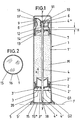
- the long, cylindrical housing 1 of the dispenser contains a piston 2. Its edge lips 2 'lead to the cylindrical housing inner wall 1'.
- the piston 2 can only be displaced in the direction of emptying (arrow x). It carries a first locking mechanism G1 on its broad surface facing the housing end on the installation side. It is a so-called clamping module 3 in the form of a radially oriented tooth 3 'having a star made of spring steel. Its diameter circumscribing the spike ends is somewhat larger than the clear diameter of the dispenser housing 1, as a result of which the spike ends, as inclined support feet, hook on the housing inner wall 1 'in a blocking manner against the direction of the arrow X.
- the clamping module 3 forms a second locking mechanism G2 in the center.
- a piston rod 4 which penetrates the piston 2 centrally, interacts with the latter.
- the radially inwardly directed teeth 3 "of the clamping module 3 engage the piston rod 4. When projected into the plane, the passage opening left by the teeth 3" is smaller than the diameter of the piston rod 4.
- the bottom end 4 'of the piston rod 4 is sharpened.
- the tip is designed as a cone 4 ".
- a movement of the coupling rod in the direction of arrow x leads to the entrainment of the piston 2 due to the non-positive coupling.
- the dispenser housing 1 forms this entrainment of the piston on the base of the housing equipped with a foot ring 5 It is a bellows that can be compressed like a bellows in the direction of the piston 2 and straightens up to its basic position
- the head piece 6 further forms a channel-like dispenser mouthpiece opening 8.
- the latter is designed in the shape of a beak, and its preferably circular opening mouth is close to the direction of extension of the housing wall and is for the times closed the storage with the help of a tightly closing plug 9.
- the stopper has the shape of a pot with the rim of the pot directed towards the mouthpiece opening. The plug is therefore highly flexible and its tight closure is optimized.
- the head piece 6 furthermore forms a pushbutton actuation surface 10 in the back of the beak-like extension circumscribing the mouthpiece opening 8. The latter extends until just before the opposite, mentally extended housing wall level and rises outwards at an angle.
- the piston rod 4 passing through the dispenser housing 1 in the longitudinal central axis y - y is connected to the head piece 6.
- the head piece 6 forms, below this pushbutton actuation surface 10, a latching recess 11 directed into the housing, into which the mushroom head-like widened upper end 4 ′′ is snapped in.
- the latching recess 11 forms a funnel-shaped extension on the piston side for easier clip assignment.
- the piston rod has an annular bead 12.
- the latter limits the actuation stroke H of the piston rod 4 by stepping against the top of a hub-like sleeve 13 in the neck 7 of the dispenser housing 1.
- the sleeve is connected to the neck 7 via spoke-like radial ribs 14.
- the guiding bushing 13 essentially closes with the top of the neck end and protrudes approximately halfway into the neck, i. H. into its opening.
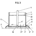
- a membrane 15 takes over the airtight seal in the bottom area of the dispenser housing, so that from there it is no longer possible to dry the pasty mass.
- the membrane 15 is connected by gluing, heat sealing or the like to the front edge 1 "of the dispenser housing.
- the membrane 15 is destroyed when the pushbutton actuation surface 10 is actuated.
- the piston rod is designed as a puncture tool and fulfills a corresponding additional function (taper 4 ").
- the taper tip lies at a distance z in front of the membrane 15 (see FIG. 3), which is smaller than the maximum, stop-defined Actuation stroke H of the piston rod 4. This results in a central perforation, so that the formation of a vacuum below the piston 2 is prevented.
- the membrane 15 is clamped in place by means of the foot ring 5 fitted onto the dispenser housing.
- the foot ring has the shape of a flat truncated cone on the outside. Its downward-facing, cylindrical standing edge 5 'brings a widened standing area for the dispenser and thus increased stability.
- the plug-in assignment can be realized by opening the foot ring 5.
- the outer surface of the cylindrical dispenser housing has an annular projection 16. The latter enters a matching annular groove 17.
- the annular groove 17 is located in a likewise cylindrical ring wall 5 "of the foot ring, which merges into a horizontal bottom wall 5 '" below.
- the inner edge portion is used for the peripheral clamping attachment, while the bottom wall 5 "'which extends immediately below the membrane 15' supports the membrane downwards.
- the bottom wall 5 Aligned to the piston rod 4, the bottom wall 5 "'leaves a passage opening 18 for the piercing tool.
- the bottom wall 5"' extends at such a vertical distance from the installation surface F, for example formed by a bracket, that the tip of the cone 4 "has this surface not touched, so the dispenser can be dispensed.
- the lower end of the dispenser housing on the assignment side has a larger clear diameter than the longer remaining section of the same (see step 20).
- the head piece 6 is covered by a cap 19.
- the latter holds frictionally or positively on a peripheral bead in the fastening area thereof between the lower edge of the headpiece and the neck 7 of the dispenser housing 1.
- the cylindrical inner wall 19 'of the cap 19 secures the position of the stopper 9 which is supported on it with its back.
Landscapes
- Engineering & Computer Science (AREA)
- Mechanical Engineering (AREA)
- Containers And Packaging Bodies Having A Special Means To Remove Contents (AREA)
- Confectionery (AREA)
- Feeding, Discharge, Calcimining, Fusing, And Gas-Generation Devices (AREA)
- Coating Apparatus (AREA)
Claims (2)
Priority Applications (1)
| Application Number | Priority Date | Filing Date | Title |
|---|---|---|---|
| AT86106569T ATE38814T1 (de) | 1985-07-26 | 1986-05-14 | Spender fuer pastoese massen. |
Applications Claiming Priority (2)
| Application Number | Priority Date | Filing Date | Title |
|---|---|---|---|
| DE3526804 | 1985-06-26 | ||
| DE19853526804 DE3526804A1 (de) | 1985-07-26 | 1985-07-26 | Spender fuer pastoese massen |
Publications (3)
| Publication Number | Publication Date |
|---|---|
| EP0210355A2 EP0210355A2 (fr) | 1987-02-04 |
| EP0210355A3 EP0210355A3 (en) | 1987-08-26 |
| EP0210355B1 true EP0210355B1 (fr) | 1988-11-23 |
Family
ID=6276858
Family Applications (1)
| Application Number | Title | Priority Date | Filing Date |
|---|---|---|---|
| EP86106569A Expired EP0210355B1 (fr) | 1985-07-26 | 1986-05-14 | Distributeur pour produits pâteux |
Country Status (4)
| Country | Link |
|---|---|
| US (1) | US4749105A (fr) |
| EP (1) | EP0210355B1 (fr) |
| AT (1) | ATE38814T1 (fr) |
| DE (2) | DE3526804A1 (fr) |
Families Citing this family (10)
| Publication number | Priority date | Publication date | Assignee | Title |
|---|---|---|---|---|
| DE3719894A1 (de) * | 1987-06-13 | 1988-12-29 | Bramlage Gmbh | Spenderstift zum auftragen streichfaehiger massen |
| DE8807844U1 (de) * | 1988-06-16 | 1988-08-18 | Pfanstiel, Erich, 7853 Steinen | Spender für Pasten o.dgl. Medien |
| ES2045237T3 (es) * | 1988-06-16 | 1994-01-16 | Erich Pfanstiel | Distribuidor para pastas o fluidos similares. |
| US5273189A (en) * | 1991-02-14 | 1993-12-28 | Societe Technique De Pulverisation - Step | Device for spraying or dispensing a fluid, the device including a member sliding in its admission duct |
| DE4423608C2 (de) * | 1994-07-06 | 1996-07-04 | Bramlage Gmbh | Spender für pastöse Massen |
| US6343718B1 (en) | 1998-10-15 | 2002-02-05 | Loctite Corporation | Unit dose dispense package |
| US20030175376A1 (en) * | 2002-03-15 | 2003-09-18 | Robert Jahn | Extruding devices and methods thereof |
| AU2018373926B2 (en) * | 2017-11-27 | 2024-03-14 | Sika Technology Ag | Two-component pressurized can |
| JP7295855B2 (ja) * | 2017-11-27 | 2023-06-21 | シーカ テクノロジー アクチェンゲゼルシャフト | 2成分型加圧缶 |
| FR3081113B1 (fr) * | 2018-05-18 | 2020-05-29 | Albea Le Treport | Piston pour reservoir d'un distributeur d'un produit fluide sans reprise d'air |
Family Cites Families (11)
| Publication number | Priority date | Publication date | Assignee | Title |
|---|---|---|---|---|
| US2829801A (en) * | 1955-06-22 | 1958-04-08 | Oil Equipment Lab Inc | Rupturable closure for pressurized containers |
| US3255935A (en) * | 1965-03-29 | 1966-06-14 | Walter B Spatz | Dispensers for fluent masses |
| US3727797A (en) * | 1971-09-07 | 1973-04-17 | P Cronan | Dual compartment spray container |
| DE2217071A1 (de) * | 1972-04-08 | 1974-01-24 | Hagen Perennatorwerk | Vorrichtung zum auspressen von viskosen massen, insbesondere pasten, wie klebstoff, dichtstoff u.dgl. aus verpackungsbehaeltern |
| US4019654A (en) * | 1976-02-25 | 1977-04-26 | Voplex Corporation | Manual cartridge dispenser |
| GB1588406A (en) * | 1976-10-26 | 1981-04-23 | Glaxo Lab Ltd | Ointment container |
| DE2945338A1 (de) * | 1979-11-09 | 1981-05-21 | Joachim 8405 Donaustauf Czech | Spender fuer pastoese produkte |
| DE3045048C2 (de) * | 1980-11-29 | 1986-04-17 | Bramlage Gmbh, 2842 Lohne | Spender für pastöse Massen |
| DE8033450U1 (de) * | 1980-12-17 | 1982-07-22 | Colgate-Palmolive Co., 10022 New York, N.Y. | Laenglicher Behaelter fuer einen Spender fuer pastoeses gut |
| US4696415A (en) * | 1985-02-26 | 1987-09-29 | Philip Meshberg | Apparatus for dispensing products from a self-sealing dispenser |
| US4673106A (en) * | 1985-10-23 | 1987-06-16 | Colgate-Palmolive Company | Dispenser for retaining toothbrush and floss |
-
1985
- 1985-07-26 DE DE19853526804 patent/DE3526804A1/de not_active Withdrawn
-
1986
- 1986-05-14 EP EP86106569A patent/EP0210355B1/fr not_active Expired
- 1986-05-14 DE DE8686106569T patent/DE3661255D1/de not_active Expired
- 1986-05-14 AT AT86106569T patent/ATE38814T1/de not_active IP Right Cessation
- 1986-07-23 US US06/889,429 patent/US4749105A/en not_active Expired - Fee Related
Also Published As
| Publication number | Publication date |
|---|---|
| DE3661255D1 (en) | 1988-12-29 |
| EP0210355A3 (en) | 1987-08-26 |
| EP0210355A2 (fr) | 1987-02-04 |
| ATE38814T1 (de) | 1988-12-15 |
| US4749105A (en) | 1988-06-07 |
| DE3526804A1 (de) | 1987-01-29 |
Similar Documents
| Publication | Publication Date | Title |
|---|---|---|
| DE3526819A1 (de) | Spender fuer pastoese massen | |
| EP0053275B1 (fr) | Distributeur pour matériel pâteux | |
| EP0084638B1 (fr) | Distributeur pour produits pâteux | |
| EP0182005B1 (fr) | Applicateur d'onguent | |
| EP0210355B1 (fr) | Distributeur pour produits pâteux | |
| EP0347546B1 (fr) | Distributeur pour produits pâteux | |
| EP0051790A1 (fr) | Distributeur pour matériel pâteux | |
| EP0194417A2 (fr) | Pompe de dosage avec soufflet de pompage pour bouteilles ou flacons similaires | |
| DE1287260B (de) | Spraygeraet | |
| WO1986001489A1 (fr) | Recipient muni d'un obturateur | |
| EP3206963A1 (fr) | Fermeture rotative comportant une capsule remplissable intérieure séparée scellée par un film s'ouvrant par rotation | |
| EP0053329A1 (fr) | Récipient pour distribuer en portions un produit de consistance pâteuse | |
| DE2309547C3 (de) | Gerät zum Füllen und Entleeren eines Flüssigkeitsbehälters, z.B. einer Pipette | |
| DE10047722A1 (de) | Von Saugluftstrom des Benutzers aktivierbare Dosiervorrichtung | |
| EP0691284B1 (fr) | Distributeur pour masses pâteuses | |
| DE102005033397A1 (de) | Inhalator für pulverförmige, insbesondere medizinische Substanzen | |
| EP0083687A1 (fr) | Distributeur de produits fluides | |
| DE4028930A1 (de) | Spender zur ausgabe pastoeser massen | |
| EP0282791B1 (fr) | Distributeur pour produits pâteux | |
| WO1994018526A1 (fr) | Dispositif de prelevement de portions de liquide | |
| EP0079539B1 (fr) | Fermeture pour un récipient pharmaceutique | |
| DE3207196A1 (de) | Spender zur abgabe fluessiger, pastoeser oder staubfoermiger fuellgueter | |
| WO1991017098A1 (fr) | Distributeur pour matieres pateuses | |
| DE4214153A1 (de) | Selbstschliessender verschluss | |
| DE2648288A1 (de) | Zerstaeuber |
Legal Events
| Date | Code | Title | Description |
|---|---|---|---|
| PUAI | Public reference made under article 153(3) epc to a published international application that has entered the european phase |
Free format text: ORIGINAL CODE: 0009012 |
|
| AK | Designated contracting states |
Kind code of ref document: A2 Designated state(s): AT BE CH DE FR GB IT LI LU NL SE |
|
| PUAL | Search report despatched |
Free format text: ORIGINAL CODE: 0009013 |
|
| AK | Designated contracting states |
Kind code of ref document: A3 Designated state(s): AT BE CH DE FR GB IT LI LU NL SE |
|
| 17P | Request for examination filed |
Effective date: 19870820 |
|
| 17Q | First examination report despatched |
Effective date: 19871119 |
|
| GRAA | (expected) grant |
Free format text: ORIGINAL CODE: 0009210 |
|
| AK | Designated contracting states |
Kind code of ref document: B1 Designated state(s): AT BE CH DE FR GB IT LI LU NL SE |
|
| PG25 | Lapsed in a contracting state [announced via postgrant information from national office to epo] |
Ref country code: IT Free format text: LAPSE BECAUSE OF FAILURE TO SUBMIT A TRANSLATION OF THE DESCRIPTION OR TO PAY THE FEE WITHIN THE PRE;WARNING: LAPSES OF ITALIAN PATENTS WITH EFFECTIVE DATE BEFORE 2007 MAY HAVE OCCURRED AT ANY TIME BEFORE 2007. THE CORRECT EFFECTIVE DATE MAY BE DIFFERENT FROM THE ONE RECORDED.SCRIBED TIME-LIMIT Effective date: 19881123 Ref country code: BE Effective date: 19881123 Ref country code: FR Free format text: THE PATENT HAS BEEN ANNULLED BY A DECISION OF A NATIONAL AUTHORITY Effective date: 19881123 Ref country code: GB Free format text: LAPSE BECAUSE OF NON-PAYMENT OF DUE FEES Effective date: 19881123 Ref country code: SE Effective date: 19881123 Ref country code: NL Effective date: 19881123 |
|
| REF | Corresponds to: |
Ref document number: 38814 Country of ref document: AT Date of ref document: 19881215 Kind code of ref document: T |
|
| REF | Corresponds to: |
Ref document number: 3661255 Country of ref document: DE Date of ref document: 19881229 |
|
| EN | Fr: translation not filed | ||
| NLV1 | Nl: lapsed or annulled due to failure to fulfill the requirements of art. 29p and 29m of the patents act | ||
| PG25 | Lapsed in a contracting state [announced via postgrant information from national office to epo] |
Ref country code: AT Effective date: 19890514 |
|
| PG25 | Lapsed in a contracting state [announced via postgrant information from national office to epo] |
Ref country code: LI Effective date: 19890531 Ref country code: CH Effective date: 19890531 Ref country code: LU Free format text: LAPSE BECAUSE OF NON-PAYMENT OF DUE FEES Effective date: 19890531 |
|
| GBV | Gb: ep patent (uk) treated as always having been void in accordance with gb section 77(7)/1977 [no translation filed] | ||
| REG | Reference to a national code |
Ref country code: CH Ref legal event code: PL |
|
| PGFP | Annual fee paid to national office [announced via postgrant information from national office to epo] |
Ref country code: DE Payment date: 19900508 Year of fee payment: 5 |
|
| PLBE | No opposition filed within time limit |
Free format text: ORIGINAL CODE: 0009261 |
|
| STAA | Information on the status of an ep patent application or granted ep patent |
Free format text: STATUS: NO OPPOSITION FILED WITHIN TIME LIMIT |
|
| 26N | No opposition filed | ||
| PG25 | Lapsed in a contracting state [announced via postgrant information from national office to epo] |
Ref country code: DE Effective date: 19920303 |