EP0210422A2 - Modulateur de pression - Google Patents
Modulateur de pression Download PDFInfo
- Publication number
- EP0210422A2 EP0210422A2 EP86108454A EP86108454A EP0210422A2 EP 0210422 A2 EP0210422 A2 EP 0210422A2 EP 86108454 A EP86108454 A EP 86108454A EP 86108454 A EP86108454 A EP 86108454A EP 0210422 A2 EP0210422 A2 EP 0210422A2
- Authority
- EP
- European Patent Office
- Prior art keywords
- piston
- pressure
- floating piston
- pressure modulator
- modulator according
- Prior art date
- Legal status (The legal status is an assumption and is not a legal conclusion. Google has not performed a legal analysis and makes no representation as to the accuracy of the status listed.)
- Granted
Links
- 238000007667 floating Methods 0.000 claims abstract description 31
- 239000012530 fluid Substances 0.000 claims description 10
- 238000004804 winding Methods 0.000 claims description 6
- 239000004065 semiconductor Substances 0.000 claims description 5
- 230000005540 biological transmission Effects 0.000 claims description 3
- 230000002146 bilateral effect Effects 0.000 claims 2
- 239000002889 diamagnetic material Substances 0.000 claims 1
- 239000000696 magnetic material Substances 0.000 claims 1
- 230000005415 magnetization Effects 0.000 claims 1
- 230000008901 benefit Effects 0.000 description 4
- 230000005291 magnetic effect Effects 0.000 description 4
- 230000000694 effects Effects 0.000 description 3
- 239000000463 material Substances 0.000 description 3
- XEEYBQQBJWHFJM-UHFFFAOYSA-N Iron Chemical compound [Fe] XEEYBQQBJWHFJM-UHFFFAOYSA-N 0.000 description 2
- 238000001816 cooling Methods 0.000 description 2
- 230000008878 coupling Effects 0.000 description 2
- 238000010168 coupling process Methods 0.000 description 2
- 238000005859 coupling reaction Methods 0.000 description 2
- 230000005284 excitation Effects 0.000 description 2
- 238000000034 method Methods 0.000 description 2
- 230000008569 process Effects 0.000 description 2
- 229910052779 Neodymium Inorganic materials 0.000 description 1
- 230000009471 action Effects 0.000 description 1
- 230000003213 activating effect Effects 0.000 description 1
- 230000004913 activation Effects 0.000 description 1
- 230000000903 blocking effect Effects 0.000 description 1
- KPLQYGBQNPPQGA-UHFFFAOYSA-N cobalt samarium Chemical compound [Co].[Sm] KPLQYGBQNPPQGA-UHFFFAOYSA-N 0.000 description 1
- 230000001351 cycling effect Effects 0.000 description 1
- 238000011161 development Methods 0.000 description 1
- 230000018109 developmental process Effects 0.000 description 1
- 230000005292 diamagnetic effect Effects 0.000 description 1
- 238000006073 displacement reaction Methods 0.000 description 1
- 230000005684 electric field Effects 0.000 description 1
- 230000005520 electrodynamics Effects 0.000 description 1
- 230000005672 electromagnetic field Effects 0.000 description 1
- 239000003822 epoxy resin Substances 0.000 description 1
- 238000000605 extraction Methods 0.000 description 1
- 230000004907 flux Effects 0.000 description 1
- 230000001771 impaired effect Effects 0.000 description 1
- 229910052742 iron Inorganic materials 0.000 description 1
- 238000012423 maintenance Methods 0.000 description 1
- QEFYFXOXNSNQGX-UHFFFAOYSA-N neodymium atom Chemical compound [Nd] QEFYFXOXNSNQGX-UHFFFAOYSA-N 0.000 description 1
- 229920000647 polyepoxide Polymers 0.000 description 1
- 230000036316 preload Effects 0.000 description 1
- 238000007639 printing Methods 0.000 description 1
- 230000009467 reduction Effects 0.000 description 1
- 229910000938 samarium–cobalt magnet Inorganic materials 0.000 description 1
- 238000007789 sealing Methods 0.000 description 1
Images
Classifications
-
- B—PERFORMING OPERATIONS; TRANSPORTING
- B60—VEHICLES IN GENERAL
- B60T—VEHICLE BRAKE CONTROL SYSTEMS OR PARTS THEREOF; BRAKE CONTROL SYSTEMS OR PARTS THEREOF, IN GENERAL; ARRANGEMENT OF BRAKING ELEMENTS ON VEHICLES IN GENERAL; PORTABLE DEVICES FOR PREVENTING UNWANTED MOVEMENT OF VEHICLES; VEHICLE MODIFICATIONS TO FACILITATE COOLING OF BRAKES
- B60T8/00—Arrangements for adjusting wheel-braking force to meet varying vehicular or ground-surface conditions, e.g. limiting or varying distribution of braking force
- B60T8/32—Arrangements for adjusting wheel-braking force to meet varying vehicular or ground-surface conditions, e.g. limiting or varying distribution of braking force responsive to a speed condition, e.g. acceleration or deceleration
- B60T8/34—Arrangements for adjusting wheel-braking force to meet varying vehicular or ground-surface conditions, e.g. limiting or varying distribution of braking force responsive to a speed condition, e.g. acceleration or deceleration having a fluid pressure regulator responsive to a speed condition
- B60T8/48—Arrangements for adjusting wheel-braking force to meet varying vehicular or ground-surface conditions, e.g. limiting or varying distribution of braking force responsive to a speed condition, e.g. acceleration or deceleration having a fluid pressure regulator responsive to a speed condition connecting the brake actuator to an alternative or additional source of fluid pressure, e.g. traction control systems
- B60T8/4809—Traction control, stability control, using both the wheel brakes and other automatic braking systems
- B60T8/4827—Traction control, stability control, using both the wheel brakes and other automatic braking systems in hydraulic brake systems
- B60T8/4863—Traction control, stability control, using both the wheel brakes and other automatic braking systems in hydraulic brake systems closed systems
-
- B—PERFORMING OPERATIONS; TRANSPORTING
- B60—VEHICLES IN GENERAL
- B60T—VEHICLE BRAKE CONTROL SYSTEMS OR PARTS THEREOF; BRAKE CONTROL SYSTEMS OR PARTS THEREOF, IN GENERAL; ARRANGEMENT OF BRAKING ELEMENTS ON VEHICLES IN GENERAL; PORTABLE DEVICES FOR PREVENTING UNWANTED MOVEMENT OF VEHICLES; VEHICLE MODIFICATIONS TO FACILITATE COOLING OF BRAKES
- B60T8/00—Arrangements for adjusting wheel-braking force to meet varying vehicular or ground-surface conditions, e.g. limiting or varying distribution of braking force
- B60T8/17—Using electrical or electronic regulation means to control braking
- B60T8/176—Brake regulation specially adapted to prevent excessive wheel slip during vehicle deceleration, e.g. ABS
- B60T8/1761—Brake regulation specially adapted to prevent excessive wheel slip during vehicle deceleration, e.g. ABS responsive to wheel or brake dynamics, e.g. wheel slip, wheel acceleration or rate of change of brake fluid pressure
- B60T8/17613—Brake regulation specially adapted to prevent excessive wheel slip during vehicle deceleration, e.g. ABS responsive to wheel or brake dynamics, e.g. wheel slip, wheel acceleration or rate of change of brake fluid pressure based on analogue circuits or digital circuits comprised of discrete electronic elements
-
- B—PERFORMING OPERATIONS; TRANSPORTING
- B60—VEHICLES IN GENERAL
- B60T—VEHICLE BRAKE CONTROL SYSTEMS OR PARTS THEREOF; BRAKE CONTROL SYSTEMS OR PARTS THEREOF, IN GENERAL; ARRANGEMENT OF BRAKING ELEMENTS ON VEHICLES IN GENERAL; PORTABLE DEVICES FOR PREVENTING UNWANTED MOVEMENT OF VEHICLES; VEHICLE MODIFICATIONS TO FACILITATE COOLING OF BRAKES
- B60T8/00—Arrangements for adjusting wheel-braking force to meet varying vehicular or ground-surface conditions, e.g. limiting or varying distribution of braking force
- B60T8/32—Arrangements for adjusting wheel-braking force to meet varying vehicular or ground-surface conditions, e.g. limiting or varying distribution of braking force responsive to a speed condition, e.g. acceleration or deceleration
- B60T8/34—Arrangements for adjusting wheel-braking force to meet varying vehicular or ground-surface conditions, e.g. limiting or varying distribution of braking force responsive to a speed condition, e.g. acceleration or deceleration having a fluid pressure regulator responsive to a speed condition
- B60T8/36—Arrangements for adjusting wheel-braking force to meet varying vehicular or ground-surface conditions, e.g. limiting or varying distribution of braking force responsive to a speed condition, e.g. acceleration or deceleration having a fluid pressure regulator responsive to a speed condition including a pilot valve responding to an electromagnetic force
-
- B—PERFORMING OPERATIONS; TRANSPORTING
- B60—VEHICLES IN GENERAL
- B60T—VEHICLE BRAKE CONTROL SYSTEMS OR PARTS THEREOF; BRAKE CONTROL SYSTEMS OR PARTS THEREOF, IN GENERAL; ARRANGEMENT OF BRAKING ELEMENTS ON VEHICLES IN GENERAL; PORTABLE DEVICES FOR PREVENTING UNWANTED MOVEMENT OF VEHICLES; VEHICLE MODIFICATIONS TO FACILITATE COOLING OF BRAKES
- B60T8/00—Arrangements for adjusting wheel-braking force to meet varying vehicular or ground-surface conditions, e.g. limiting or varying distribution of braking force
- B60T8/32—Arrangements for adjusting wheel-braking force to meet varying vehicular or ground-surface conditions, e.g. limiting or varying distribution of braking force responsive to a speed condition, e.g. acceleration or deceleration
- B60T8/34—Arrangements for adjusting wheel-braking force to meet varying vehicular or ground-surface conditions, e.g. limiting or varying distribution of braking force responsive to a speed condition, e.g. acceleration or deceleration having a fluid pressure regulator responsive to a speed condition
- B60T8/44—Arrangements for adjusting wheel-braking force to meet varying vehicular or ground-surface conditions, e.g. limiting or varying distribution of braking force responsive to a speed condition, e.g. acceleration or deceleration having a fluid pressure regulator responsive to a speed condition co-operating with a power-assist booster means associated with a master cylinder for controlling the release and reapplication of brake pressure through an interaction with the power assist device, i.e. open systems
- B60T8/447—Reducing the boost of the power-assist booster means to reduce brake pressure
-
- H—ELECTRICITY
- H01—ELECTRIC ELEMENTS
- H01F—MAGNETS; INDUCTANCES; TRANSFORMERS; SELECTION OF MATERIALS FOR THEIR MAGNETIC PROPERTIES
- H01F7/00—Magnets
- H01F7/06—Electromagnets; Actuators including electromagnets
- H01F7/066—Electromagnets with movable winding
-
- H—ELECTRICITY
- H01—ELECTRIC ELEMENTS
- H01F—MAGNETS; INDUCTANCES; TRANSFORMERS; SELECTION OF MATERIALS FOR THEIR MAGNETIC PROPERTIES
- H01F7/00—Magnets
- H01F7/06—Electromagnets; Actuators including electromagnets
- H01F7/08—Electromagnets; Actuators including electromagnets with armatures
- H01F7/16—Rectilinearly-movable armatures
- H01F7/1607—Armatures entering the winding
- H01F7/1615—Armatures or stationary parts of magnetic circuit having permanent magnet
-
- H—ELECTRICITY
- H01—ELECTRIC ELEMENTS
- H01F—MAGNETS; INDUCTANCES; TRANSFORMERS; SELECTION OF MATERIALS FOR THEIR MAGNETIC PROPERTIES
- H01F7/00—Magnets
- H01F7/06—Electromagnets; Actuators including electromagnets
- H01F7/08—Electromagnets; Actuators including electromagnets with armatures
- H01F7/18—Circuit arrangements for obtaining desired operating characteristics, e.g. for slow operation, for sequential energisation of windings, for high-speed energisation of windings
-
- H—ELECTRICITY
- H01—ELECTRIC ELEMENTS
- H01F—MAGNETS; INDUCTANCES; TRANSFORMERS; SELECTION OF MATERIALS FOR THEIR MAGNETIC PROPERTIES
- H01F7/00—Magnets
- H01F7/06—Electromagnets; Actuators including electromagnets
- H01F7/08—Electromagnets; Actuators including electromagnets with armatures
- H01F7/121—Guiding or setting position of armatures, e.g. retaining armatures in their end position
- H01F7/122—Guiding or setting position of armatures, e.g. retaining armatures in their end position by permanent magnets
Definitions
- the invention relates to a pressure modulator for ABS systems according to the preamble of the main claim.
- Hydraulic brake systems for example with multi-circuit tandem master cylinders are known (DE-OS 27 23 734); it is also known to assign ABS functions to such brake systems, for example to switch electrically actuable multi-way solenoid valves into the output brake pressure lines to the wheel brake cylinders, which implement the desired and required ABS control functions, but usually work in the event of a pressure drop so that the respective one Pressure line from the master brake cylinder to the connected wheel brake cylinders is at least interrupted and pressure medium is fed to the return flow. If the pressure rises again, the connection is then made to the master brake cylinder again, each with any pressure time curve and with the possibility to implement pressure maintenance functions.
- ABS functions with the aid of electrically actuable multi-way solenoid valves in the main brake lines can be problematic since pressurized brake fluid or brake fluid is practically “lost" and this lost brake fluid in the area of a pressure supply device with a pump, pressure storage container and corresponding pressure switches must be pumped back to the high pressure required for the braking process. Furthermore, such systems causing an interruption or a drain in the brake lines must be very reliable and fail-safe, since otherwise there could be a risk that too much brake fluid under high pressure will be drained.
- the invention has for its object, on the one hand, to leave the brake circuit completely closed even when ABS functions are being implemented, but on the other hand to ensure that the normal brake functions can continue to be carried out in the event of component failure, including in the electrical field, further ensuring that the implementation the main brake cylinder area is separated from the respective wheel brake cylinder area from ABS functions and this receives the required brake pressure modulation, but on the other hand compensates for slow Volume changes in the brake fluid is possible.
- the pressure modulator according to the invention achieves this object with the characterizing features of the main claim and has the advantage that when the brake is not actuated, the bypass line with throttle establishes a hydraulic connection between the area of the master brake cylinder and the respective wheel brake cylinder, but on the other hand when the brake is actuated and / or when ABS is implemented Functions this line is closed by the moving floating piston.
- the invention therefore ensures the advantages achieved by arranging a piston / cylinder unit directly in the respective main brake lines to the wheel brake cylinders, such as maintaining the closed system, avoiding direct mechanical coupling (error protection) and the possibility of arranging the floating piston as close as possible to the respective wheel brake cylinder and has the further advantages that in the event of a leak in the area of the respective wheel brake cylinder, the associated brake circuit cannot run out.
- the floating piston works in its cylindrical sliding guide with a narrow air gap, so that large forces can be generated;
- the coil is carried by the floating piston, so that particularly good cooling of the coil can also be achieved by the pressure fluid flowing around it.
- the measures listed in the subclaims allow advantageous developments and improvements of the pressure modulator specified in the main claim for the implementation of ABS functions in motor vehicle brake systems.
- the symmetrical winding of the coil on the floating piston is particularly advantageous here, so that both air gaps can be used in the case of a ring permanent magnet surrounding the coil and magnetized in the longitudinal direction.
- the electrodynamic ABS can - modulator with very little overhead so-called for realizing ASR functions are used, namely in that only the current flow direction in the coil turns is reversed when changing from ABS functions to ASR functions, and it is therefore possible to achieve a brake pressure build-up instead of a brake pressure reduction, so that, regardless of the driver's will, a wheel which may spin during start-up experiences a desired deceleration.
- a corresponding ASR control device can either control the respective excitation or actuator coil of the modulator via switching transistors of the opposite type (PNP - NPN) or the two modulators can be wound in opposite directions and alternately switched on.
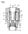
- FIG. 1 shows a first exemplary embodiment in a simplified form indicating a basic concept
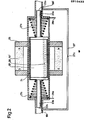
- FIG. 2 shows various details of the floating piston bearing in a different configuration in part from FIG. 1
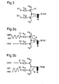
- FIG. 3 shows a possible exemplary embodiment for FIGS. 3a and 3b specify a reversal of the current direction in the actuator coil, which makes it possible to use ASR functions.
- an outer housing 11 which on both sides at lla and llb forms connecting pieces with which the pressure modulator is connected directly into the respective brake line from the vehicle master brake cylinder to the individual wheel brake cylinders; an adapter piece inserted into the brake line can also be used for this.
- the housing 11 forms a central cylindrical sliding guide 12 for the slidable mounting of a floating piston 13, which in normal braking transmits the pressure resulting from arrow A from the master brake cylinder untranslated - i.e. the same end faces of the floating piston on both sides - in the respective connected wheel brake cylinder.
- the operation of the floating piston when the ABS function is used is such that the floating piston 13 provided with one or more permanent magnets 21, either in the form of preferably evenly distributed over the circumference as magnetic segments or as a ring magnet, by the action of the excited coil 15 in Towards its upper stop 14 (back) is pulled - during the initial braking there has been a displacement of the floating piston 13 downwards - so that the floating piston 13 works against the brake pressure from the master brake cylinder and produces an increase in volume in the area of the wheel brake cylinder, thereby causing any over time-running printing functions can be realized.
- a failure of the control of the pressure modulator obviously does not impair the normal braking function.
- the pressure transmission or application takes place via rod end faces 22a, 22b, the rod end face 22a facing the wheel brake cylinder area and the rod surface 22b of the floating piston 13 'receiving pressure from the master brake cylinder.
- the piston chamber is sealed in the area of the floating piston 13 ′ on both sides rods 23a, 23b continuing in a tapered shape, the.
- Soft magnetic floating piston carries the coil windings 24.
- the permanent magnets ensuring the movement of the floating piston 13 'under the influence of the magnetic forces generated are mounted on the outside of the diamagnetic cylinder housing 11', by holders 25 made of soft iron, which at the same time feed the magnetic flux to the respective air gap as pole pieces, the permanent magnet also here again as a single hollow cylindrical permanent magnet, preferably magnetized in the axial direction, made of a material with the highest possible remanence and the highest possible energy content per volume - this applies to all permanent magnet materials, e.g. neodymium or samarium cobalt - or several permanent magnets in the form of segments, preferably uniformly over the outer circumference of the housing 11 'are distributed.
- the coil is preferably molded onto the piston body, using a suitable epoxy resin or similar material, and it will be understood that the piston has one or more axial bores 26 to be flowed through without loss of chamber fluid when moving, with sealing in the area the tapered rod piston on both sides.
- the current is supplied to the coil 24 arranged on the movable piston 13 ', preferably via positioning springs 27a, 27b, which are also provided on the ground side, the outer connections are shown at 28a and 28b.
- the throttled bypass line is again provided with 20 ', that is, as with all components which differ only slightly, with a comma at the top while otherwise retaining the reference number and sniffing holes 19a', 19b 'on both sides of the bypass line 20' are immediately run over by the rod pistons when the piston moves initially and therefore closed.
- FIG. 3 shows a possible embodiment of a control device for activating the excitation or actuator coil 15 or 24, as is used in the pressure modulator embodiments of FIGS. 1 and 2.
- the control device has two inputs EI and E2, the ABS modulation signal in question being fed to the input E1 in the ABS case; the ASR modulation signal in question is fed to the input E2 if this normal case should occur.
- the two inputs work over each because of series resistors Rvl and Rv2 on the control inputs of two switching transistors T1 and T2 connected in series, whereby of course other suitable semiconductor switches, possibly also relays, can be used here.
- the transistor T1 is a so-called PNP transistor, which connects the actuator coil 15 to a positive supply voltage + U R , the other connection point of which is connected to ground or zero line, while the same actuator coil is connected via transistor T2 as an NPN transistor 15 or 24 is connected to a negative supply voltage -U B , depending on the activation of the transistors T1 and T2 in the ABS or ASR case, which results in a reversal of the current direction in the coil windings.
- FIGS. 1 and 2 it can be seen that in the case of the realization of ABS functions, the pistons 13 and 13 'are pulled in the direction of the master cylinder connection under the effect of the electromagnetic field with pressure relief at the wheel cylinder connection
- This function corresponds to the actuation case shown in FIG. 3a, in which a blocking signal, approximately -1 2 V with a correspondingly negative supply voltage -U B, is fed to the terminal E2 and the transistor T1 is actuated over time by an alternating ABS signal voltage, with the current direction through the actuator coil resulting from the arrow A in this case.
- the transistor T1 is then blocked by appropriate signal application at the input El and an ASR signal that changes according to the requirements is present at the input E2 with the now opposite current direction through. the actuator coil according to arrow B of FIG. 3b. It can also be seen that an effective build-up of brake pressure is possible in this way, since, as already mentioned above, the piston immediately passes over the sniffing hole opening 19, 19 'of the bypass line 20, 20', in which, incidentally, there is one anyway Throttle 20a, 20a 'is located.
- the desired ASR functions can also be realized, for example, based on the same modulator units as shown in FIGS. 1 and 2, that the respective actuator coils 15, 24 are designed as partial coils, each wound in opposite directions for the ABS case and the ASR case and, depending on the rule, can be controlled alternatively.
- a reversal of the current direction in a coil can, however, also be achieved by the arrangement of four switching transistors in bridge form with the coil in the bridge diagonal, which is known per se, in which case transistors which are diagonally opposite one another are then jointly controlled in a conductive manner.
Landscapes
- Physics & Mathematics (AREA)
- Engineering & Computer Science (AREA)
- Electromagnetism (AREA)
- Fluid Mechanics (AREA)
- Transportation (AREA)
- Mechanical Engineering (AREA)
- Power Engineering (AREA)
- Regulating Braking Force (AREA)
- Measuring Pulse, Heart Rate, Blood Pressure Or Blood Flow (AREA)
- Amplifiers (AREA)
- Liquid Crystal Substances (AREA)
Priority Applications (1)
| Application Number | Priority Date | Filing Date | Title |
|---|---|---|---|
| AT86108454T ATE57142T1 (de) | 1985-07-23 | 1986-06-20 | Druckmodulator. |
Applications Claiming Priority (2)
| Application Number | Priority Date | Filing Date | Title |
|---|---|---|---|
| DE19853526191 DE3526191A1 (de) | 1985-07-23 | 1985-07-23 | Druckmodulator |
| DE3526191 | 1985-07-23 |
Publications (3)
| Publication Number | Publication Date |
|---|---|
| EP0210422A2 true EP0210422A2 (fr) | 1987-02-04 |
| EP0210422A3 EP0210422A3 (en) | 1987-06-10 |
| EP0210422B1 EP0210422B1 (fr) | 1990-10-03 |
Family
ID=6276438
Family Applications (1)
| Application Number | Title | Priority Date | Filing Date |
|---|---|---|---|
| EP86108454A Expired - Lifetime EP0210422B1 (fr) | 1985-07-23 | 1986-06-20 | Modulateur de pression |
Country Status (4)
| Country | Link |
|---|---|
| EP (1) | EP0210422B1 (fr) |
| JP (1) | JPS6317155A (fr) |
| AT (1) | ATE57142T1 (fr) |
| DE (2) | DE3526191A1 (fr) |
Cited By (5)
| Publication number | Priority date | Publication date | Assignee | Title |
|---|---|---|---|---|
| DE4002865A1 (de) * | 1990-02-01 | 1991-08-08 | Teves Gmbh Alfred | Anfahr- ud bremsschlupfgeregelte, hydraulische bremsanlage, insbesondere fuer kraftfahrzeuge |
| US5127713A (en) * | 1987-12-12 | 1992-07-07 | Alfred Teves Gmbh | Anti-lock brake system for automotive vehicles |
| EP0651910A4 (fr) * | 1992-07-15 | 1995-03-24 | Lord Corp | Procede et appareil permettant la realisation d'une connexion electrique avec un element mobile. |
| WO1996012632A1 (fr) * | 1994-10-24 | 1996-05-02 | Hilite Industries, Inc. | Structure encochee d'un repartiteur en ligne |
| FR2811467A1 (fr) * | 2000-07-06 | 2002-01-11 | Renault | Actionneur de soupape electrodynamique et agencement d'une pluralite de tels actionneurs |
Families Citing this family (4)
| Publication number | Priority date | Publication date | Assignee | Title |
|---|---|---|---|---|
| DE3803079A1 (de) * | 1988-02-03 | 1989-08-17 | Bosch Gmbh Robert | Elektromechanisch betaetigbarer druckmodulator fuer blockierschutz- und antriebsschlupfregelanlagen |
| JPH0560974U (ja) * | 1992-01-29 | 1993-08-10 | 株式会社ユニシアジェックス | 車両用スリップ制御装置 |
| KR20020047563A (ko) * | 2000-12-13 | 2002-06-22 | 이계안 | 차량의 적재량에 따라 제동력이 조절되는 공압식 제동장치 |
| JP2009227417A (ja) * | 2008-03-24 | 2009-10-08 | Fujifilm Corp | テープ巻取装置 |
Family Cites Families (3)
| Publication number | Priority date | Publication date | Assignee | Title |
|---|---|---|---|---|
| US4113323A (en) * | 1977-06-15 | 1978-09-12 | Goodyear Aerospace Corporation | Anti-skid power valve |
| GB1585646A (en) * | 1977-12-21 | 1981-03-11 | Macdonald D | Brake pressure modulating device |
| DE3237106A1 (de) * | 1982-10-07 | 1984-04-12 | Werner 5231 Peterslahr Berk | Automatisches - intervall - bremssystem |
-
1985
- 1985-07-23 DE DE19853526191 patent/DE3526191A1/de not_active Withdrawn
-
1986
- 1986-06-20 DE DE8686108454T patent/DE3674664D1/de not_active Expired - Lifetime
- 1986-06-20 EP EP86108454A patent/EP0210422B1/fr not_active Expired - Lifetime
- 1986-06-20 AT AT86108454T patent/ATE57142T1/de not_active IP Right Cessation
- 1986-07-23 JP JP61171956A patent/JPS6317155A/ja active Pending
Cited By (6)
| Publication number | Priority date | Publication date | Assignee | Title |
|---|---|---|---|---|
| US5127713A (en) * | 1987-12-12 | 1992-07-07 | Alfred Teves Gmbh | Anti-lock brake system for automotive vehicles |
| DE4002865A1 (de) * | 1990-02-01 | 1991-08-08 | Teves Gmbh Alfred | Anfahr- ud bremsschlupfgeregelte, hydraulische bremsanlage, insbesondere fuer kraftfahrzeuge |
| DE4002865C2 (de) * | 1990-02-01 | 2001-12-13 | Continental Teves Ag & Co Ohg | Anfahr- ud bremsschlupfgeregelte, hydraulische Bremsanlage für Kraftfahrzeuge |
| EP0651910A4 (fr) * | 1992-07-15 | 1995-03-24 | Lord Corp | Procede et appareil permettant la realisation d'une connexion electrique avec un element mobile. |
| WO1996012632A1 (fr) * | 1994-10-24 | 1996-05-02 | Hilite Industries, Inc. | Structure encochee d'un repartiteur en ligne |
| FR2811467A1 (fr) * | 2000-07-06 | 2002-01-11 | Renault | Actionneur de soupape electrodynamique et agencement d'une pluralite de tels actionneurs |
Also Published As
| Publication number | Publication date |
|---|---|
| DE3526191A1 (de) | 1987-02-05 |
| JPS6317155A (ja) | 1988-01-25 |
| EP0210422B1 (fr) | 1990-10-03 |
| EP0210422A3 (en) | 1987-06-10 |
| DE3674664D1 (de) | 1990-11-08 |
| ATE57142T1 (de) | 1990-10-15 |
Similar Documents
| Publication | Publication Date | Title |
|---|---|---|
| EP0209737B1 (fr) | Modulateur de pression pour systèmes anti-patinage | |
| EP1132274B1 (fr) | Modulateur de pression de freinage pour système de freinage électronique | |
| DE3131856A1 (de) | Fahrzeugbremsanlage | |
| EP0302250A1 (fr) | Valve magnétique avec coéfficients de débit variables | |
| EP0210422B1 (fr) | Modulateur de pression | |
| EP0307579A1 (fr) | Installation de valves commandées magnétiquement | |
| EP0051800A1 (fr) | Dispositif d'antiblocage | |
| DE4002333A1 (de) | Elektrisch steuerbare druckmittelbremse fuer fahrzeuge | |
| DE2606797A1 (de) | Vorrichtung zum bremsen eines sich drehenden elementes | |
| DE4415068C2 (de) | Bistabiles Magnetventil | |
| EP0210421A1 (fr) | Amplificateur de force de freinage pour installations de freinage de véhicules | |
| EP2736789B1 (fr) | Dispositif destiné à soumettre au moins une bobine électrique d'un frein sur rail d'un véhicule ferroviaire à l'effet d'au moins une impulsion électrique | |
| EP0643650B1 (fr) | Systeme antiblocage | |
| DE69101075T2 (de) | Bremsdruckmodulator für Kraftfahrzeuge. | |
| EP0209817A1 (fr) | Amplificateur et modulateur de pression | |
| DE3213007A1 (de) | Antiblockierregelsystem | |
| DE1946650A1 (de) | Druckmittelbetaetigte Schalteinrichtung | |
| DE3809338C1 (en) | Control valve with relay action for motor vehicles or trailers | |
| DE10245916A1 (de) | Bremsdruckmodulator | |
| DE1946177A1 (de) | Fahrzeugbremssystem | |
| EP0363615A2 (fr) | Installation de freinage à air comprimé | |
| DE4020164A1 (de) | Elektromagnetisch betaetigtes ventil | |
| EP0701076A1 (fr) | Soupape électromagnétique | |
| DE10204553A1 (de) | Elektromagnetisch betätigbare Ventileinrichtung sowie Anordnung zur Ansteuerung einer solchen Ventileinrichtung | |
| DE2731334C2 (fr) |
Legal Events
| Date | Code | Title | Description |
|---|---|---|---|
| PUAI | Public reference made under article 153(3) epc to a published international application that has entered the european phase |
Free format text: ORIGINAL CODE: 0009012 |
|
| AK | Designated contracting states |
Kind code of ref document: A2 Designated state(s): AT DE FR GB IT |
|
| PUAL | Search report despatched |
Free format text: ORIGINAL CODE: 0009013 |
|
| AK | Designated contracting states |
Kind code of ref document: A3 Designated state(s): AT DE FR GB IT |
|
| 17P | Request for examination filed |
Effective date: 19871104 |
|
| 17Q | First examination report despatched |
Effective date: 19881115 |
|
| GRAA | (expected) grant |
Free format text: ORIGINAL CODE: 0009210 |
|
| AK | Designated contracting states |
Kind code of ref document: B1 Designated state(s): AT DE FR GB IT |
|
| REF | Corresponds to: |
Ref document number: 57142 Country of ref document: AT Date of ref document: 19901015 Kind code of ref document: T |
|
| ET | Fr: translation filed | ||
| REF | Corresponds to: |
Ref document number: 3674664 Country of ref document: DE Date of ref document: 19901108 |
|
| GBT | Gb: translation of ep patent filed (gb section 77(6)(a)/1977) | ||
| ITF | It: translation for a ep patent filed | ||
| PG25 | Lapsed in a contracting state [announced via postgrant information from national office to epo] |
Ref country code: GB Effective date: 19910620 Ref country code: AT Effective date: 19910620 |
|
| PLBE | No opposition filed within time limit |
Free format text: ORIGINAL CODE: 0009261 |
|
| STAA | Information on the status of an ep patent application or granted ep patent |
Free format text: STATUS: NO OPPOSITION FILED WITHIN TIME LIMIT |
|
| 26N | No opposition filed | ||
| GBPC | Gb: european patent ceased through non-payment of renewal fee | ||
| PG25 | Lapsed in a contracting state [announced via postgrant information from national office to epo] |
Ref country code: FR Effective date: 19920228 |
|
| PG25 | Lapsed in a contracting state [announced via postgrant information from national office to epo] |
Ref country code: DE Effective date: 19920401 |
|
| REG | Reference to a national code |
Ref country code: FR Ref legal event code: ST |
|
| PG25 | Lapsed in a contracting state [announced via postgrant information from national office to epo] |
Ref country code: IT Free format text: LAPSE BECAUSE OF NON-PAYMENT OF DUE FEES;WARNING: LAPSES OF ITALIAN PATENTS WITH EFFECTIVE DATE BEFORE 2007 MAY HAVE OCCURRED AT ANY TIME BEFORE 2007. THE CORRECT EFFECTIVE DATE MAY BE DIFFERENT FROM THE ONE RECORDED. Effective date: 20050620 |