EP0210426A1 - Dispositif de commande à distance - Google Patents
Dispositif de commande à distance Download PDFInfo
- Publication number
- EP0210426A1 EP0210426A1 EP86108488A EP86108488A EP0210426A1 EP 0210426 A1 EP0210426 A1 EP 0210426A1 EP 86108488 A EP86108488 A EP 86108488A EP 86108488 A EP86108488 A EP 86108488A EP 0210426 A1 EP0210426 A1 EP 0210426A1
- Authority
- EP
- European Patent Office
- Prior art keywords
- remote control
- driver
- control device
- pin
- lever
- Prior art date
- Legal status (The legal status is an assumption and is not a legal conclusion. Google has not performed a legal analysis and makes no representation as to the accuracy of the status listed.)
- Granted
Links
- 230000005540 biological transmission Effects 0.000 claims abstract description 20
- 230000033001 locomotion Effects 0.000 claims description 23
- 230000008878 coupling Effects 0.000 claims description 16
- 238000010168 coupling process Methods 0.000 claims description 16
- 238000005859 coupling reaction Methods 0.000 claims description 16
- 230000006835 compression Effects 0.000 claims description 10
- 238000007906 compression Methods 0.000 claims description 10
- 230000009471 action Effects 0.000 claims description 8
- 238000006073 displacement reaction Methods 0.000 description 4
- 235000002595 Solanum tuberosum Nutrition 0.000 description 2
- 244000061456 Solanum tuberosum Species 0.000 description 2
- 238000000034 method Methods 0.000 description 2
- 230000008569 process Effects 0.000 description 2
- 230000001105 regulatory effect Effects 0.000 description 2
- 230000007704 transition Effects 0.000 description 2
- 241000196324 Embryophyta Species 0.000 description 1
- 229910000831 Steel Inorganic materials 0.000 description 1
- 230000003247 decreasing effect Effects 0.000 description 1
- 230000000694 effects Effects 0.000 description 1
- 238000003306 harvesting Methods 0.000 description 1
- 230000003993 interaction Effects 0.000 description 1
- 238000004519 manufacturing process Methods 0.000 description 1
- 239000002184 metal Substances 0.000 description 1
- 238000003801 milling Methods 0.000 description 1
- 239000000203 mixture Substances 0.000 description 1
- 230000007480 spreading Effects 0.000 description 1
- 239000010959 steel Substances 0.000 description 1
Images


Classifications
-
- A—HUMAN NECESSITIES
- A01—AGRICULTURE; FORESTRY; ANIMAL HUSBANDRY; HUNTING; TRAPPING; FISHING
- A01B—SOIL WORKING IN AGRICULTURE OR FORESTRY; PARTS, DETAILS, OR ACCESSORIES OF AGRICULTURAL MACHINES OR IMPLEMENTS, IN GENERAL
- A01B63/00—Lifting or adjusting devices or arrangements for agricultural machines or implements
- A01B63/02—Lifting or adjusting devices or arrangements for agricultural machines or implements for implements mounted on tractors
- A01B63/10—Lifting or adjusting devices or arrangements for agricultural machines or implements for implements mounted on tractors operated by hydraulic or pneumatic means
-
- G—PHYSICS
- G05—CONTROLLING; REGULATING
- G05G—CONTROL DEVICES OR SYSTEMS INSOFAR AS CHARACTERISED BY MECHANICAL FEATURES ONLY
- G05G5/00—Means for preventing, limiting or returning the movements of parts of a control mechanism, e.g. locking controlling member
- G05G5/06—Means for preventing, limiting or returning the movements of parts of a control mechanism, e.g. locking controlling member for holding members in one or a limited number of definite positions only
-
- G—PHYSICS
- G05—CONTROLLING; REGULATING
- G05G—CONTROL DEVICES OR SYSTEMS INSOFAR AS CHARACTERISED BY MECHANICAL FEATURES ONLY
- G05G5/00—Means for preventing, limiting or returning the movements of parts of a control mechanism, e.g. locking controlling member
- G05G5/12—Means for preventing, limiting or returning the movements of parts of a control mechanism, e.g. locking controlling member for holding members in an indefinite number of positions, e.g. by a toothed quadrant
- G05G5/20—Means for preventing, limiting or returning the movements of parts of a control mechanism, e.g. locking controlling member for holding members in an indefinite number of positions, e.g. by a toothed quadrant by locking a quadrant, rod, or the like carried by the member
- G05G5/24—Means for preventing, limiting or returning the movements of parts of a control mechanism, e.g. locking controlling member for holding members in an indefinite number of positions, e.g. by a toothed quadrant by locking a quadrant, rod, or the like carried by the member by positive interengagement, e.g. by a pawl
-
- Y—GENERAL TAGGING OF NEW TECHNOLOGICAL DEVELOPMENTS; GENERAL TAGGING OF CROSS-SECTIONAL TECHNOLOGIES SPANNING OVER SEVERAL SECTIONS OF THE IPC; TECHNICAL SUBJECTS COVERED BY FORMER USPC CROSS-REFERENCE ART COLLECTIONS [XRACs] AND DIGESTS
- Y10—TECHNICAL SUBJECTS COVERED BY FORMER USPC
- Y10T—TECHNICAL SUBJECTS COVERED BY FORMER US CLASSIFICATION
- Y10T74/00—Machine element or mechanism
- Y10T74/18—Mechanical movements
- Y10T74/18888—Reciprocating to or from oscillating
- Y10T74/1892—Lever and slide
-
- Y—GENERAL TAGGING OF NEW TECHNOLOGICAL DEVELOPMENTS; GENERAL TAGGING OF CROSS-SECTIONAL TECHNOLOGIES SPANNING OVER SEVERAL SECTIONS OF THE IPC; TECHNICAL SUBJECTS COVERED BY FORMER USPC CROSS-REFERENCE ART COLLECTIONS [XRACs] AND DIGESTS
- Y10—TECHNICAL SUBJECTS COVERED BY FORMER USPC
- Y10T—TECHNICAL SUBJECTS COVERED BY FORMER US CLASSIFICATION
- Y10T74/00—Machine element or mechanism
- Y10T74/20—Control lever and linkage systems
- Y10T74/20207—Multiple controlling elements for single controlled element
- Y10T74/20372—Manual controlling elements
- Y10T74/20384—Levers
- Y10T74/2039—Pair of levers
-
- Y—GENERAL TAGGING OF NEW TECHNOLOGICAL DEVELOPMENTS; GENERAL TAGGING OF CROSS-SECTIONAL TECHNOLOGIES SPANNING OVER SEVERAL SECTIONS OF THE IPC; TECHNICAL SUBJECTS COVERED BY FORMER USPC CROSS-REFERENCE ART COLLECTIONS [XRACs] AND DIGESTS
- Y10—TECHNICAL SUBJECTS COVERED BY FORMER USPC
- Y10T—TECHNICAL SUBJECTS COVERED BY FORMER US CLASSIFICATION
- Y10T74/00—Machine element or mechanism
- Y10T74/20—Control lever and linkage systems
- Y10T74/20396—Hand operated
-
- Y—GENERAL TAGGING OF NEW TECHNOLOGICAL DEVELOPMENTS; GENERAL TAGGING OF CROSS-SECTIONAL TECHNOLOGIES SPANNING OVER SEVERAL SECTIONS OF THE IPC; TECHNICAL SUBJECTS COVERED BY FORMER USPC CROSS-REFERENCE ART COLLECTIONS [XRACs] AND DIGESTS
- Y10—TECHNICAL SUBJECTS COVERED BY FORMER USPC
- Y10T—TECHNICAL SUBJECTS COVERED BY FORMER US CLASSIFICATION
- Y10T74/00—Machine element or mechanism
- Y10T74/20—Control lever and linkage systems
- Y10T74/20576—Elements
- Y10T74/20582—Levers
- Y10T74/2063—Stops
Definitions
- the invention relates to a remote control device with a driver, a transmission member and a remote control lever.
- EP-A2-0 131 711 describes a remote control device for a lever of a three-point device coupling of an agricultural tractor, which is used to adjust the lever arranged in a driver's cab of the agricultural tractor from outside the driver's cabin, so that lower links belonging to the three-point device coupling are used can be raised or lowered without an operator having to climb onto the tractor.
- the lever may only be moved in a certain area. This depends, among other things, on whether the control device can perform position control and tension resistance control or not.
- the driver is designed as a gear and the transmission member as a rack with a Bowden cable.
- the gear wheel is provided with teeth on only part of its circumference and rotatably mounted in a housing. It is basically in engagement with the rack and can be connected to the remote control lever via a simple pin connection against the action of a spring element.
- the rack takes on the form and function of a slide, which is longitudinally displaceable in the housing by rotating the gear and thereby adjusts the Bowden cable.
- Two stops are provided on the housing, which limit the pivoting range of the remote control lever to a predetermined range, which corresponds to the empty range.
- a pawl snaps into the gearwheel as soon as the rack is at the end of the empty area. The pawl is then held in a special recess in the carriage during its further displacement from the lever so that the gear cannot be rotated forward or backward.
- This remote control device has the disadvantage that the pin connection can be circumvented by placing the remote control lever laterally on the pin, thus leading the rotary movement of the gear wheel to the pivoting movement of the remote control lever and moving the rack beyond the predetermined range. Likewise, the remote control lever can also be pressed frictionally against the gearwheel and the rack can thus be moved beyond the predetermined range.
- the object underlying the invention is seen in further developing the remote control device in such a way that its function becomes safer.
- driver is rigidly connected to the remote control lever and can be connected to the transmission member in only one engagement relationship.
- the driver can only be connected to the transmission member in the same position, and a shift of the desired operating range is not possible.
- This measure can be achieved in that the driver and the transmission link only fit together in one of many possible positions, or in that there is only a single connection possibility.
- a single recess in the slide into which the spring-loaded driver pin can be inserted is sufficient to ensure that the driver is always clearly connected to the slide.
- the Federbel Stung ensures a positive fit and gives an acoustic and / or noticeable indication that a positive fit has occurred when the driver pin snaps in while the compression spring is suddenly released.
- the remote control lever can be pivoted together with the driver in any position of the transmission member and thus also the slide out of the inoperative position on the slide and the recess provided in it, and since the driver pin is spring-loaded, it can on the surface of the slide in the predetermined area are moved so that it engages in the recess as soon as it reaches it. It is therefore irrelevant which position the driver pin is currently in relation to the slide, since it can be brought into engagement with the slide via the movement of the remote control lever, provided that the driver pin can still cover the predetermined area.
- the automatic latching of the driver pin is effected in particular in a simple manner by prestressing it in the direction of the recess.
- the remote control lever can always be brought into an inoperative position and held in this, so that by an unwanted operation or external force, z. B. by a falling object, no force can be applied to the driver and the transmission member.
- a positive connection between the driver pin and the slide is produced as quickly as possible if the starting position of the slide is predetermined in such a way that the path of movement of the driver pin overlaps with the recess in the shortest possible way.
- the remote control device experiences a useful use when it is used to operate the three-point implement coupling of an agricultural tractor is used, and in particular when the three-point implement coupling can be operated from the implement attached to the agricultural tractor, this implement can be optimally guided by a person on the implement.
- Such an application is very useful when operating a potato planter, a planting machine, a potato harvester or a chopper, because the person sitting on such a machine can recognize better and faster than the person operating the tractor whether the machine goes deeper into the ground or must be lifted further out of this in order to achieve the best possible plant cover or the least possible clod attack.
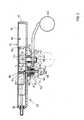
- a tractor 10 shown in FIG. 1 with its outlines having a cabin 12 is provided at its rear end with a three-point device coupling 14, by means of which a connection to, but not to be attached, one shown device can be manufactured.
- the device can be a plow, seed drill, harrow or other machine.
- the three-point device coupling 14 has two lower links 16, which are connected to a lifting shaft 22 via lifting struts 18 and lifting arms 20 and have ball eyelets 24 on the device side.
- the lifting shaft 22 itself can be rotated via a lifting cylinder (not shown) which acts on it eccentrically, while the lower link 16 can swivel vertically by a spring bar (not shown in the drawing).
- the pivoting movement is effected by the rotating lifting shaft 22 and transmitted to the lower link 16 via the lifting arms 20 and the lifting struts 18.
- the three-point device coupling 14 includes an upper link not included in the drawing, via which the attached device is held in a vertical or approximately vertical position during the pivoting process of the lower link 16.
- a control device to control the rotation of the lifting shaft 22, a control device, not shown, is provided with a control lever 26 in the cabin 12 in the agricultural tractor 10, which, in addition to the control lever 26, can also be used to input pulses via the spring bar.
- a control device is superimposed on the control device, which enables the attached device to be guided at least analogously to a position control and a tension resistance control. If necessary, a mixture of both control types, namely a mixed control, can also be provided.
- position control means that the attached device is always held in the same vertical position with respect to the agricultural tractor 10, this being determined directly via the position of the control lever 26, so that the attached device always maintains the same working depth.
- Train resistance regulation means that the attached device always maintains a working depth that corresponds to a certain pull resistance when pulling through the ground. The tensile resistance is transmitted to the control device by a proportional bend of the spring rod and there initiates a lifting or lowering process of the three-point device coupling 14.
- the control lever 26 is driven in a known embodiment in a backdrop, not shown, and is movable within a predetermined range. If the position control is selected as the type of control, then the lower link 16 is raised or lowered proportionally to the adjustment path of the control lever 26 in the setting, in such a way that the lower link 16 is in its lowest position when the control lever 26 is at the front End of the backdrop abuts, and assume its uppermost position when the control lever 26 is located at the rear end of the backdrop.
- the area is subdivided into an empty area and a control area if the tension resistance control is selected as the control type, the empty area extending from the front end of the backdrop and the control area extending from the rear end of the backdrop.
- An adjustment of the control lever 26 in the empty range as long as the tension resistance control is selected, has no effect on the three-point device clutch 14.
- An adjustment of the control lever 26 in the control range leads to an uncontrolled raising or lowering of the lower, non-loaded handlebars 16 because of their vertical pivoting movement in the tension resistance control takes place almost exclusively in dependence on the impulses experienced by the spring bar or another tension resistance transmission element.
- a remote control device or device 30 is provided in a rear outer area 28 of the agricultural tractor 10, which is operated via a Bowden cable 32 or another linkage is connected to the control lever 26 and can transmit movement to it to a limited extent, so that the lower link 16 of the three-point device coupling 14 not only directly from the cabin 12 via the control lever 26, but also indirectly from outside the cabin 12 can be raised or lowered via the remote control device 30.
- This is particularly important in order to be able to bring the height of the lower links 16 to the correct coupling height when attaching the device, which may be very difficult from the cabin 12, but can be carried out very easily if a person operating the three-point device coupling 14 is right next to the device to be attached.
- the remote control device 30 is designed as follows and as can be seen from FIGS. 2 and 3.
- the remote control device 30 is accordingly essentially composed of a housing 34, a cover 36, a slide 38, a driver 40, a lever 42 and a lock 44.
- the housing 34 consists of a dimensionally stable plastic and takes the form of a trapezoid placed on a rectangle, the broad side of the trapezoid standing on the rectangle and the rectangle extending at one end beyond the trapezoid.
- the housing 34 has an edge 46 within which the cover 36, the Schlit th 38 and the driver 40 are arranged.
- the housing 34 In its end region of the elongated rectangle 48, the housing 34 has an opening 50 through which a piece of rope 52 of the Bowden cable 32 described above and connected to the control lever 26 extends.
- a sleeve 54 of the Bowden cable 32 is rigidly connected to the housing 34 via a screw sleeve 56 and thus enables the transmission of a pulling or pushing movement.
- the Bowden cable 32, the slide 38, the rope piece 52, the sleeve 54 and the screw sleeve 56 are components of the transmission member or the linkage.
- the edge 46 has a fold 58 on its inner circumference, which serves for the positive reception of the cover 36, so that it is always held in the same position with respect to the housing 34.
- the side of the housing 34 facing this fold 58 represents the rear side 60 of the housing 34 in this exemplary embodiment.
- a housing elevation 64 is provided, which reinforces the housing 34 and in one Stepped bore 66 and a bore 68 are provided, the bore 68 being concentrically surrounded by an annular groove 70 and a wall 72 remaining between the annular groove 70 and the bore 68.
- the annular groove 70 is provided with an internal thread 74, and the wall 72 is broken through at two diametrically opposite points 76.
- the stepped bore 66 has a region of large and a region of small diameter 78 and 80, the region of large diameter 78 being located on the front side 62 and the region of small diameter 80 on the rear side 60.
- a bearing bushing 82 is inserted into the area of large diameter 78, the inside diameter of which corresponds to the inside diameter of the stepped bore 66 in the area of small diameter 80.
- the bearing bush 82 can be made of a wear-resistant plastic or gunmetal, for example, and is flush with the housing 34 on the front side 62.
- the lid 36 which can also be made of a dimensionally stable plastic or sheet metal, has the same shape as the housing 34, but its outer dimensions are somewhat smaller so that it fits into the fold 58 of the edge 46. It is designed to be relatively thin and on its inside facing the front side 62 of the housing 34 is provided with a holding element 84, a stop 86 and two guide pins 88 and 90, the holding element 84 and the bellows 86 extending almost over the entire height of the edge 46 and the two guide pins 88, 90 extend over approximately one third of the edge 46.
- the holding element 84, the stop 86 and the guide pins 88, 90 can be glued, screwed onto the cover 36 or made in one piece therewith.
- the holding element 84 has on its right side in the drawing, which is located against the stop 86, a slope 92, which is interrupted by a groove 94.
- the groove 94 runs out on the lower side via a chamfer 96 into the bevel 92.
- the stop 86 can be designed in the form of a pin or the like and is preferably round in cross section.
- the guide pins 88, 90 are also in the form of a pin or the like. However, they can also be designed in the manner of guide shoes. The function of the guide pins 88, 90 is explained in more detail below. With regard to the region of the edge 46 of the housing 34 located at the bottom in FIG. 2, the groove 94 in the holding element 84 and the stop 86 are at the same distance.
- the two guide pins 88, 90 also lie on a line lying parallel to this area of the edge 46.
- the cover 36 and the housing 34 can either be glued or cast together, or they can be held together by screws. The type of attachment is not shown in the
- the carriage 38 has the cross section of an irregular-shaped tra pezes with rounded edges. Its height corresponds to the inside dimension of the housing 34 in the end region of the elongated rectangle 48, and its width essentially corresponds to the height of the edge 46.
- the length of the carriage 38 extends from the left end of the elongated rectangle 48 to approximately the center of the trapezoid on the rectangle. In particular, it is dimensioned such that the carriage 38 is still below the holding element 84 when it can no longer be moved to the right.
- the right end region of the carriage 38 in the drawing runs in a slope 98, starting from the lower edge in the direction of the end region of the elongated rectangle 48, at an angle of approximately 45 degrees.
- a threaded bore 100 extends from the left end of the slide 38 in the drawing to approximately a third of its length, into which the cable piece 52 of the Bowden cable 32 is screwed, for which purpose it is provided at the end with a threaded pin 102. Relative to an end face 104 of the slide 38 visible from the left, the threaded bore 100 is located at the intersection of the two diagonals. On the side of the slide 38 facing the cover 36, a guide groove 106 extending over its entire length is milled into it, the width and depth of which are dimensioned such that it can overlap the two guide pins 88, 90.
- the interaction of the two guide pins 88, 90 and the guide groove 106 results in a longitudinal guidance of the slide 38, so that it is always guided parallel to the lower edge 46 of the housing 34.
- the upper side of the carriage 38 also bears against the holding element 84 and is also guided by the latter in the housing 34 during its longitudinal movement.
- a recess or driver groove 110 which extends across its width and merges into the top 108 via a chamfer 112 on both sides. Between the chamfer 112 facing the bevel 98 and the bevel 98 there remains a small area which is approximately the width of the center slave slot 110 corresponds.
- the depth of the driving groove 110 corresponds approximately to the depth of the groove 94 in the holding element 84.
- the driver 40 is composed of a block 114, a compression spring 116, a driver pin 118 and a disk 120.
- the block 114 has the outer shape of a cuboid, which is closed at its lower end by a cap 122.
- the thickness of the block 114 corresponds approximately to the distance between the cover 36 and the housing 34, that is to say the height of the edge 46.
- the block 114 is drilled through in the direction of its longitudinal axis and in the center and thus has a cylindrical guide 124 for the driving pin 118. This guide 124 also extends through the cap 122, so that the driver pin 118 is slidably guided at one end in the block 114 and at the other end in the cap 122.
- a bore or an opening 126 of a larger diameter than the guide 124, into which the compression spring 116 is inserted is provided between the cap 122 and the guide 124.
- an opening 126 it can extend from the side facing the housing 34 to the side of the block 114 facing the cover 36, which can be achieved most simply by a milling process.
- the bore 126 has a stop surface 128.
- the driver pin 118 thus extends between the guide 124 in the block 114 and the guide 124 in the cap 122 also through the bore 126.
- the Driver pin 118 attached to the disk 120. This can, for example, be welded onto the driving pin 118 or held in an annular groove in this, but this is not shown in more detail.
- the compression spring 116 is inserted under prestress and thus causes the driving pin 118 to always be moved in the direction of the cap 122, so that the end 130 of the driving pin 118 facing the cap 122 is pushed out of the guide 124 of the cap 122 until the disk 120 comes to rest on the cap 122 with the side facing away from the compression spring 116.
- the driver pin 118 projects beyond the cap 122 by a certain amount which corresponds at least to the depth of the driver groove 110. However, it preferably projects beyond the depth of the driver groove 110 by a little more.
- the length of the driving pin 118 is, however, also designed so that even if the disk 120 comes to rest on the cap 122, the driving pin 118 is therefore in the most remote position from the block 114, it is still in its end region facing the block 114 the guide 124 is held.
- the cap 122 can be screwed or welded onto the block 114. If an opening 126 is provided in the block 114 instead of the bore and the disk 120 is held on the driver pin 118 by means of a tension pin or a locking ring, then the cap 122 and the block 114 can also be formed as one part. In this case, the pressure spring 116 would first have to be pushed into the opening 126, then the washer 120 between the pressure spring 116 and the part of the block 114 replacing the cap 122. The driver pin 118 could then be pushed from one of the guides 124 through the compression spring 116 and the disk 120, the compression spring 116 compressed to the stop surface 128 and the disk 120 secured against the driver pin 118 by means of the dowel pin or the like.
- a threaded bore 132 for receiving a connecting bolt 134 belonging to the driver 40 intended.
- This threaded bore 132 is designed as a blind bore and extends perpendicular to the guide 124 in the block 114. It is therefore designed as a blind bore, so that it is excluded that the connecting bolt 134 can be screwed into the guide 124 and the movement of the driving pin 118 therein prevented.
- the connecting bolt 134 could also be welded onto the block 114 or formed from one part with it.
- the connecting bolt 134 extends from the block 114 through the housing 34, specifically through the bearing bush 82 and projects with a flattened shaft part 136 over the front side 62 of the housing 34.
- a recess 138 is provided in the lever 42, so that this can make a rotationally fixed connection with the connecting bolt 134 in the region of its flattened portion.
- the shaft part 136 is so long that, even if it is encompassed by the lever 42, it still protrudes with a threaded part 142 over the lever 42.
- a nut 144 is screwed onto this threaded part 142, by means of which the lever 42 can be fixed on the shaft part 136 by its abutment on the stop 140.
- the remote control lever or lever 42 is made of a flat steel or a thick sheet and is of elongated shape. At its end remote from the connecting bolt 134, it is provided with a ball 146 which is attached or screwed onto it and which enables the lever 42 to be gripped more comfortably and easily.
- the rotationally fixed connection of the connecting bolt 134 both to the block 114 and to the lever 42 transfers and causes a pivoting movement of the lever 42 in the bearing bush 82 directly to the block 114 there also its pivoting.
- the axis of symmetry of the lever 42 and that of the block 114 run at an angle of approximately 45 degrees to one another.
- the lock 44 is composed of a threaded sleeve 148 with an inner bore 150, a spring 152, a locking pin 154 and a plate 156, the threaded sleeve 148 carrying the thread on the outer circumference and into the internally threaded annular groove 70 in the front 62 of the housing 34 can be screwed in.
- the outer diameter of the locking pin 154 corresponds to the inner diameter of the bore 68 in the front 62 of the housing 34 and is therefore guided in the direction of its longitudinal central axis during a sliding movement in the latter.
- the inner diameter of the inner bore 150 is almost identical to the outer diameter of the locking pin 154.
- the length of the locking pin 154 is dimensioned such that it extends continuously through both the bore 68 and through the inner bore 150 and then with a pin end 158 over the Threaded sleeve 148 protrudes, wherein a grip ball 160 is also screwed onto the pin end 158, which makes it easier to axially shift the locking pin 154.
- the plate 156 is placed on the locking pin 154 and held thereon, for example in that the plate 156 is designed as a spreading disc which is inserted into a on the circumference of the locking pin 154 incorporated groove, not shown, can be inserted.
- the plate 156 has an inner side 164 and an outer side 166, the inner side 164 being considered to be the one which points towards the housing 34 in the installed state, while the outer side 166 is to be considered the one which in the installed state to the Grip ball 160 shows.
- the spring 152 is provided, which according to abuts the above on the outside 166 of the plate 156.
- the plate 156 is provided with two openings 168 which correspond to the size and the cross section of the wall 72 arranged on the front side 62 of the housing 34 and concentrically surrounding the bore 68.
- the locking pin 154 and with it also the plate 156 is rotated such that the openings 168 are aligned with the wall 72, then the locking pin 154 can be moved axially, and the plate 156 slides on the wall 72, the locking pin 154 in the direction of the housing 34 is moved by the spring 152 while it must be pulled in the opposite direction by a person against the force of the spring 152.
- the inner diameter of the spring 152 care must be taken that it is larger than the outer diameter of the wall 72, so that it does not come into contact with the wall 72 during the axial movement of the locking pin 154 on the housing 34 and thus prevents the locking pin 154 dips sufficiently far into the housing 34.
- the tension resistance control has been selected as the control type
- the control lever 26 has assumed a position in the cabin 12 which corresponds to the lowest position of the lower link 16, and that the driver 40 pivots so far via the lever 42 has been that the driver pin 118 comes into contact in the groove 94 in the holding element 84.
- the carriage 38 will be located in the end region of the elongated rectangle 48 and will come to rest on the inner end face on the left in the figures.
- the lock 44 assumes a state in which the plate 156 can slide on the wall 72 and is brought to bear against the front side 62 of the housing 34 by the action of the spring 152. In this position, the locking pin 154 extends so far into the housing 34 that it engages in the movement path of the end 130 extending from the block 114 of the driving pin 118.
- the tractor 10 is now moved backwards by one person to a device not to be attached, for example a disc harrow.
- a device not to be attached for example a disc harrow.
- the agricultural tractor 10 is stopped and the lower links 16 are moved upwards so that the ball eyelets 24 are approximately at the same height as the coupling points lying on the disc harrow.
- the person can often only care whether the height of the ball eyelets 24 corresponds to the height of the coupling points on the disc harrow.
- the person will get off the tractor 10 and go backwards to push the lower link 16 with the ball eyelets 24 over trailer bolts provided on the disc harrow. If the ball eyelets 24 are now below the attachment bolts, the person will pull the locking pin 154 outwards, ie in the direction out of the housing 34, via the handle ball 160 until the plate 156 no longer engages over the wall 72. Then the locking pin 154 is rotated a little about its longitudinal axis and released, so that the plate 156 is pressed under the action of the spring 152 on the wall 72, that is to say in a position in which the locking pin 154 no longer moves into the movement path of the driving pin 118 intervenes.
- the lever 42 is returned to its starting position, i. H. pivoted back into the position in which the driver pin 118 is held in the groove 94 in the holding element 84, and the locking pin 154 pushed into the housing 34.
- the lock 44 does not serve to block the lever 42 in its turning capacity under normal circumstances, which is already achieved by the engagement of the driving pin 118 in the groove 94 in the holding element 84, but prevents it from being caused by an unwanted external force, about by a falling object, the lever is pivoted and unintentionally causes an adjustment of the lower link 16.
- the lever 42 provided the lock 44 is open, can be pivoted in any position of the slide 38 and as long as the range of motion of the driving pin 118 covers with the driving groove 110 at any point, are brought into positive engagement with the carriage 38.
- the driver pin 118 will then only slide along the surface 108 of the carriage 38 until it engages in the driver groove 110.
- the housing 34 with its entire contents does not necessarily have to be attached to the agricultural tractor 10, for example to its rear fender.
- the stop 86 could be omitted and the shape of the housing 34 such that the block 114 with the driving pin 118 can be pivoted even further, endlessly, when the carriage 38 has assumed its position which corresponds to the upper position of the corresponds to the lower link 16, and that via the bevel 92 on the holding element 84 the driver pin 118 can again be inserted into the groove 94 for the non-operating position, but from the other side, which is also particularly advantageous.
- the entire pivoting range of the lever 42 is characterized in FIG. 2 by the inner partial arc and the part of the pivoting range in which the slide 38 can be moved by the lever 42 by the outer partial arc.
Landscapes
- Engineering & Computer Science (AREA)
- Physics & Mathematics (AREA)
- Automation & Control Theory (AREA)
- Life Sciences & Earth Sciences (AREA)
- General Physics & Mathematics (AREA)
- Soil Sciences (AREA)
- Environmental Sciences (AREA)
- Mechanical Engineering (AREA)
- Mechanical Control Devices (AREA)
- Agricultural Machines (AREA)
- Lock And Its Accessories (AREA)
- Ultra Sonic Daignosis Equipment (AREA)
- Soil Working Implements (AREA)
- Infusion, Injection, And Reservoir Apparatuses (AREA)
- Selective Calling Equipment (AREA)
Priority Applications (1)
| Application Number | Priority Date | Filing Date | Title |
|---|---|---|---|
| AT86108488T ATE58792T1 (de) | 1985-07-03 | 1986-06-21 | Fernbetaetigungsvorrichtung. |
Applications Claiming Priority (2)
| Application Number | Priority Date | Filing Date | Title |
|---|---|---|---|
| DE19853523762 DE3523762A1 (de) | 1985-07-03 | 1985-07-03 | Fernbetaetigungsvorrichtung |
| DE3523762 | 1985-07-03 |
Publications (2)
| Publication Number | Publication Date |
|---|---|
| EP0210426A1 true EP0210426A1 (fr) | 1987-02-04 |
| EP0210426B1 EP0210426B1 (fr) | 1990-11-28 |
Family
ID=6274839
Family Applications (1)
| Application Number | Title | Priority Date | Filing Date |
|---|---|---|---|
| EP86108488A Expired - Lifetime EP0210426B1 (fr) | 1985-07-03 | 1986-06-21 | Dispositif de commande à distance |
Country Status (6)
| Country | Link |
|---|---|
| US (1) | US4713981A (fr) |
| EP (1) | EP0210426B1 (fr) |
| AT (1) | ATE58792T1 (fr) |
| DE (2) | DE3523762A1 (fr) |
| ES (1) | ES8706984A1 (fr) |
| ZA (1) | ZA864913B (fr) |
Cited By (1)
| Publication number | Priority date | Publication date | Assignee | Title |
|---|---|---|---|---|
| FR2709226A1 (fr) * | 1993-08-27 | 1995-03-03 | Renault Agriculture | Dispositif et procédé de commande du relevage hydraulique d'un tracteur agricole. |
Families Citing this family (8)
| Publication number | Priority date | Publication date | Assignee | Title |
|---|---|---|---|---|
| DE4017136A1 (de) * | 1990-05-28 | 1991-12-05 | Kloeckner Humboldt Deutz Ag | Vorrichtung zur arretierung eines betaetigungshebels |
| DE9104571U1 (de) * | 1991-04-15 | 1991-07-18 | Wolf - Geräte GmbH Vertriebsgesellschaft KG, 5240 Betzdorf | Leistungssteuerungsvorrichtung, insbesondere für zum Antrieb von Rasenmähern vorgesehenen Brennkraftmaschinen |
| US6170606B1 (en) | 1996-06-28 | 2001-01-09 | Safety Dynamicon, Inc. | Analog control |
| DE19720327C1 (de) * | 1997-05-15 | 1998-04-30 | Preh Elektro Feinmechanik | Bedienelement |
| DE19902355A1 (de) | 1999-01-21 | 2000-08-03 | Oris Fahrzeugteile Riehle H | Anhängekupplung |
| DE202010001555U1 (de) * | 2010-01-29 | 2010-04-08 | Bruder Spielwaren Gmbh + Co. Kg | Spielzeug-Baugruppe sowie Spielfahrzeug |
| US10660254B2 (en) * | 2018-08-15 | 2020-05-26 | Deere & Company | Frame and leveling assembly for agricultural implement |
| EP3841858B1 (fr) * | 2019-12-25 | 2023-07-26 | Kubota Corporation | Véhicule de travail |
Citations (4)
| Publication number | Priority date | Publication date | Assignee | Title |
|---|---|---|---|---|
| DE808084C (de) * | 1950-03-04 | 1951-07-09 | Gottfried Kelkel | Feststellbare Fussbremse fuer Motorfahrzeuge, insbesondere fuer Traktoren, mit dem Zahnsegment des Bremspedals zugeordneter Sperrklinke |
| DE3318114A1 (de) * | 1983-05-18 | 1984-11-22 | International Harvester Company Mbh, 4040 Neuss | Betaetigungsvorrichtung zur zusaetzlichen fernbetaetigung der lageregelung eines hydraulisch krafthebers |
| DE8425315U1 (de) * | 1984-08-27 | 1986-01-02 | Gesellschaft für Steuerungstechnik mbH & Co, 6332 Ehringshausen | Gebersystem mit zwei Eingabestellen zur Steuerung eines Aggregates |
| DE3433092A1 (de) * | 1984-09-08 | 1986-03-20 | Gesellschaft für Steuerungstechnik mbH & Co, 6332 Ehringshausen | Gebergeraet fuer zug-druck-kabel o.dgl. |
Family Cites Families (5)
| Publication number | Priority date | Publication date | Assignee | Title |
|---|---|---|---|---|
| US2509639A (en) * | 1948-04-27 | 1950-05-30 | Ian W M Harker | Drive mechanism |
| US3117465A (en) * | 1961-12-06 | 1964-01-14 | Eicrmann Henry | Single lever engine and transmission control |
| US3827724A (en) * | 1973-02-16 | 1974-08-06 | Deere & Co | Coupling device |
| US3938402A (en) * | 1974-08-14 | 1976-02-17 | Eastman Kodak Company | Manipulator |
| ZA823150B (en) * | 1981-05-14 | 1983-03-30 | Massey Ferguson Services Nv | Lever mechanism |
-
1985
- 1985-07-03 DE DE19853523762 patent/DE3523762A1/de active Granted
-
1986
- 1986-06-17 ES ES556140A patent/ES8706984A1/es not_active Expired
- 1986-06-21 EP EP86108488A patent/EP0210426B1/fr not_active Expired - Lifetime
- 1986-06-21 AT AT86108488T patent/ATE58792T1/de not_active IP Right Cessation
- 1986-06-21 DE DE8686108488T patent/DE3675835D1/de not_active Expired - Lifetime
- 1986-07-02 ZA ZA864913A patent/ZA864913B/xx unknown
- 1986-07-03 US US06/881,886 patent/US4713981A/en not_active Expired - Fee Related
Patent Citations (4)
| Publication number | Priority date | Publication date | Assignee | Title |
|---|---|---|---|---|
| DE808084C (de) * | 1950-03-04 | 1951-07-09 | Gottfried Kelkel | Feststellbare Fussbremse fuer Motorfahrzeuge, insbesondere fuer Traktoren, mit dem Zahnsegment des Bremspedals zugeordneter Sperrklinke |
| DE3318114A1 (de) * | 1983-05-18 | 1984-11-22 | International Harvester Company Mbh, 4040 Neuss | Betaetigungsvorrichtung zur zusaetzlichen fernbetaetigung der lageregelung eines hydraulisch krafthebers |
| DE8425315U1 (de) * | 1984-08-27 | 1986-01-02 | Gesellschaft für Steuerungstechnik mbH & Co, 6332 Ehringshausen | Gebersystem mit zwei Eingabestellen zur Steuerung eines Aggregates |
| DE3433092A1 (de) * | 1984-09-08 | 1986-03-20 | Gesellschaft für Steuerungstechnik mbH & Co, 6332 Ehringshausen | Gebergeraet fuer zug-druck-kabel o.dgl. |
Cited By (1)
| Publication number | Priority date | Publication date | Assignee | Title |
|---|---|---|---|---|
| FR2709226A1 (fr) * | 1993-08-27 | 1995-03-03 | Renault Agriculture | Dispositif et procédé de commande du relevage hydraulique d'un tracteur agricole. |
Also Published As
| Publication number | Publication date |
|---|---|
| EP0210426B1 (fr) | 1990-11-28 |
| DE3675835D1 (de) | 1991-01-10 |
| ES8706984A1 (es) | 1987-07-01 |
| ATE58792T1 (de) | 1990-12-15 |
| DE3523762C2 (fr) | 1987-12-23 |
| US4713981A (en) | 1987-12-22 |
| DE3523762A1 (de) | 1987-01-15 |
| ES556140A0 (es) | 1987-07-01 |
| ZA864913B (en) | 1988-03-30 |
Similar Documents
| Publication | Publication Date | Title |
|---|---|---|
| EP0628236B1 (fr) | Dispositif réglable en hauteur | |
| DE19944749C2 (de) | Seitenstrebe für einen Unterlenker eines Traktors | |
| EP0210426B1 (fr) | Dispositif de commande à distance | |
| DE3322551C2 (de) | Zwischenstück zum Ausschalten der Seitenbeweglichkeit von Unterlenkern eines Ackerschleppers | |
| EP0146116A2 (fr) | Attelage de remorque à fonctionnement automatique | |
| DE1129751B (de) | Vorrichtung zur automatischen Lagen- und Zugkraftsteuerung fuer landwirtschaftliche Schlepper-Anbaugeraete und -Anhaengegeraete | |
| EP0387529A2 (fr) | Circuit hydraulique comportant une soupape de commande | |
| DE10352209A1 (de) | Sämaschine | |
| DE2502944B2 (de) | Vorrichtung zum Aus- und Einschalten des Spiels bei einer Anhängerkupplung | |
| DE3434247C2 (fr) | ||
| DE3318114C2 (de) | Betätigungsvorrichtung zur zusätzlichen Fernbetätigung der Lageregelung eines hydraulischen Krafthebers | |
| DE3411161A1 (de) | Bodenbearbeitungsmaschine, insbesondere kreiselegge | |
| EP3721690A1 (fr) | Entretoise latérale de stabilisation d' un bras inférieur d'un dispositif de montage d'une machine agricole | |
| EP0181947B1 (fr) | Roue porteuse oscillante pour charrues-brabant | |
| DE4004285C1 (fr) | ||
| DE2538616A1 (de) | Vorrichtung zur gelenkigen zuordnung von insbesondere landwirtschaftlichen arbeitsgeraeten, wie pfluegen u. dgl. an zugmaschinen, wie traktoren | |
| DE69421642T2 (de) | Heuwerbungsmaschine | |
| DE2320393B2 (fr) | ||
| DE3605779C2 (fr) | ||
| AT275942B (de) | Schnellkuppelvorrichtung zum Anbau von landwirtschaftlichen Geräten an das Dreipunktgestänge von Schleppern | |
| DE1782664C3 (de) | Pflug, insbesondere Anhänge- oder Aufsattelpflug | |
| DE1757400A1 (de) | Steuervorrichtung fuer hydraulische Kraftheber an Zugfahrzeugen,insbesondere Ackerschleppern | |
| DE3217428C1 (de) | Steuersystem für Sämaschinen, insbesondere Drillmaschinen | |
| DE1287347B (de) | Schlepper, insbesondere Weinbergschlepper, mit Dreipunktgeraetekupplung | |
| DE3918611A1 (de) | Anhaengerkupplung |
Legal Events
| Date | Code | Title | Description |
|---|---|---|---|
| PUAI | Public reference made under article 153(3) epc to a published international application that has entered the european phase |
Free format text: ORIGINAL CODE: 0009012 |
|
| AK | Designated contracting states |
Kind code of ref document: A1 Designated state(s): AT BE CH DE FR GB IT LI |
|
| 17P | Request for examination filed |
Effective date: 19870710 |
|
| 17Q | First examination report despatched |
Effective date: 19890202 |
|
| ITF | It: translation for a ep patent filed | ||
| GRAA | (expected) grant |
Free format text: ORIGINAL CODE: 0009210 |
|
| AK | Designated contracting states |
Kind code of ref document: B1 Designated state(s): AT BE CH DE FR GB IT LI |
|
| REF | Corresponds to: |
Ref document number: 58792 Country of ref document: AT Date of ref document: 19901215 Kind code of ref document: T |
|
| REF | Corresponds to: |
Ref document number: 3675835 Country of ref document: DE Date of ref document: 19910110 |
|
| ET | Fr: translation filed | ||
| GBT | Gb: translation of ep patent filed (gb section 77(6)(a)/1977) | ||
| PGFP | Annual fee paid to national office [announced via postgrant information from national office to epo] |
Ref country code: GB Payment date: 19910516 Year of fee payment: 6 |
|
| PGFP | Annual fee paid to national office [announced via postgrant information from national office to epo] |
Ref country code: CH Payment date: 19910528 Year of fee payment: 6 |
|
| PGFP | Annual fee paid to national office [announced via postgrant information from national office to epo] |
Ref country code: AT Payment date: 19910603 Year of fee payment: 6 |
|
| PGFP | Annual fee paid to national office [announced via postgrant information from national office to epo] |
Ref country code: FR Payment date: 19910610 Year of fee payment: 6 |
|
| PGFP | Annual fee paid to national office [announced via postgrant information from national office to epo] |
Ref country code: BE Payment date: 19910619 Year of fee payment: 6 |
|
| PGFP | Annual fee paid to national office [announced via postgrant information from national office to epo] |
Ref country code: DE Payment date: 19910817 Year of fee payment: 6 |
|
| PLBE | No opposition filed within time limit |
Free format text: ORIGINAL CODE: 0009261 |
|
| STAA | Information on the status of an ep patent application or granted ep patent |
Free format text: STATUS: NO OPPOSITION FILED WITHIN TIME LIMIT |
|
| 26N | No opposition filed | ||
| PG25 | Lapsed in a contracting state [announced via postgrant information from national office to epo] |
Ref country code: GB Effective date: 19920621 Ref country code: AT Effective date: 19920621 |
|
| PG25 | Lapsed in a contracting state [announced via postgrant information from national office to epo] |
Ref country code: LI Effective date: 19920630 Ref country code: CH Effective date: 19920630 Ref country code: BE Effective date: 19920630 |
|
| BERE | Be: lapsed |
Owner name: DEERE & CY Effective date: 19920630 |
|
| GBPC | Gb: european patent ceased through non-payment of renewal fee |
Effective date: 19920621 |
|
| PG25 | Lapsed in a contracting state [announced via postgrant information from national office to epo] |
Ref country code: FR Effective date: 19930226 |
|
| REG | Reference to a national code |
Ref country code: CH Ref legal event code: PL |
|
| PG25 | Lapsed in a contracting state [announced via postgrant information from national office to epo] |
Ref country code: DE Effective date: 19930302 |
|
| REG | Reference to a national code |
Ref country code: FR Ref legal event code: ST |
|
| PG25 | Lapsed in a contracting state [announced via postgrant information from national office to epo] |
Ref country code: IT Free format text: LAPSE BECAUSE OF NON-PAYMENT OF DUE FEES;WARNING: LAPSES OF ITALIAN PATENTS WITH EFFECTIVE DATE BEFORE 2007 MAY HAVE OCCURRED AT ANY TIME BEFORE 2007. THE CORRECT EFFECTIVE DATE MAY BE DIFFERENT FROM THE ONE RECORDED. Effective date: 20050621 |