EP0210431A1 - Tür für an der Wand montierte Möbel - Google Patents
Tür für an der Wand montierte Möbel Download PDFInfo
- Publication number
- EP0210431A1 EP0210431A1 EP86108528A EP86108528A EP0210431A1 EP 0210431 A1 EP0210431 A1 EP 0210431A1 EP 86108528 A EP86108528 A EP 86108528A EP 86108528 A EP86108528 A EP 86108528A EP 0210431 A1 EP0210431 A1 EP 0210431A1
- Authority
- EP
- European Patent Office
- Prior art keywords
- door
- container
- counterweight
- edge
- doors
- Prior art date
- Legal status (The legal status is an assumption and is not a legal conclusion. Google has not performed a legal analysis and makes no representation as to the accuracy of the status listed.)
- Granted
Links
- 230000000717 retained effect Effects 0.000 claims abstract description 5
- 230000003019 stabilising effect Effects 0.000 claims description 2
- 230000005294 ferromagnetic effect Effects 0.000 claims 2
- 238000005286 illumination Methods 0.000 description 3
- 238000010276 construction Methods 0.000 description 2
- 239000002184 metal Substances 0.000 description 2
- 229920003023 plastic Polymers 0.000 description 2
- 239000004033 plastic Substances 0.000 description 2
- 208000020221 Short stature Diseases 0.000 description 1
- 239000003302 ferromagnetic material Substances 0.000 description 1
- 230000000670 limiting effect Effects 0.000 description 1
- 230000014759 maintenance of location Effects 0.000 description 1
- 230000036961 partial effect Effects 0.000 description 1
- 230000002829 reductive effect Effects 0.000 description 1
- 230000000284 resting effect Effects 0.000 description 1
- 238000004513 sizing Methods 0.000 description 1
Images

Classifications
-
- E—FIXED CONSTRUCTIONS
- E05—LOCKS; KEYS; WINDOW OR DOOR FITTINGS; SAFES
- E05D—HINGES OR SUSPENSION DEVICES FOR DOORS, WINDOWS OR WINGS
- E05D15/00—Suspension arrangements for wings
- E05D15/26—Suspension arrangements for wings for folding wings
- E05D15/262—Suspension arrangements for wings for folding wings folding vertically
-
- E—FIXED CONSTRUCTIONS
- E06—DOORS, WINDOWS, SHUTTERS, OR ROLLER BLINDS IN GENERAL; LADDERS
- E06B—FIXED OR MOVABLE CLOSURES FOR OPENINGS IN BUILDINGS, VEHICLES, FENCES OR LIKE ENCLOSURES IN GENERAL, e.g. DOORS, WINDOWS, BLINDS, GATES
- E06B3/00—Window sashes, door leaves, or like elements for closing wall or like openings; Layout of fixed or moving closures, e.g. windows in wall or like openings; Features of rigidly-mounted outer frames relating to the mounting of wing frames
- E06B3/32—Arrangements of wings characterised by the manner of movement; Arrangements of movable wings in openings; Features of wings or frames relating solely to the manner of movement of the wing
- E06B3/48—Wings connected at their edges, e.g. foldable wings
- E06B3/481—Wings foldable in a zig-zag manner or bi-fold wings
- E06B3/482—Wings foldable in a zig-zag manner or bi-fold wings specially adapted for furniture
-
- E—FIXED CONSTRUCTIONS
- E05—LOCKS; KEYS; WINDOW OR DOOR FITTINGS; SAFES
- E05Y—INDEXING SCHEME ASSOCIATED WITH SUBCLASSES E05D AND E05F, RELATING TO CONSTRUCTION ELEMENTS, ELECTRIC CONTROL, POWER SUPPLY, POWER SIGNAL OR TRANSMISSION, USER INTERFACES, MOUNTING OR COUPLING, DETAILS, ACCESSORIES, AUXILIARY OPERATIONS NOT OTHERWISE PROVIDED FOR, APPLICATION THEREOF
- E05Y2900/00—Application of doors, windows, wings or fittings thereof
- E05Y2900/20—Application of doors, windows, wings or fittings thereof for furniture, e.g. cabinets
Definitions
- This invention relates to a door-type closure device for wall-mounted furniture units.
- Known wall-mounted furniture units particularly kitchen units, generally consist of a parallelepiped container which is fitted to the room wall at a height generally less than 1.5 m and is closed by one or more doors hinged to the vertical edges of said container.
- a further drawback is that the space occupied by the open doors is considerable and if lateral light sources are used these open doors create shadow zones which prevent complete illumination of the furniture unit interior.
- Wall-mounted furniture units are also known which are closed at their front by a single door hinged to the upper horizontal edge.
- One drawback of this closure system is that the single door can, as in the preceding case, hinder effective illumination of the furniture unit interior.
- a further drawback is that the door can be kept in its raised (open) position only by the provision of " compasses”, springs or other retention members, which on the one hand represent bulky anti-aesthetic elements, and on the other hand do not enable the door to remain in intermediate positions.
- a still further drawback is the practical impossibility of completely opening the door, because it would then lie at too high a level and could not be easily gripped by the user, especially if of short stature, in order to close the furniture unit.
- a door-type closure device for wall-mounted furniture units in the form of a container closable at its front by a pair of doors, characterised by comprising a first door hinged at its upper edge to the front edge of'the container roof, and a second door of height substantially equal to the first and hinged at its upper edge to the lower edge of this latter and having the ends of its lower edge retained by and slidable along two guide rails provided on the front vertical edge of the container side walls, and by further comprising a balancing member comprising at least one cable connected to said lower edge of said second door, and at least one counterweight which is operable from the outside and which when the two doors are completely folded back to open the furniture unit is positioned in correspondence with the base of said container, whereas when the two doors are coplanar to close the furniture unit it is positioned in corrispondence with the roof of said container.
- the two doors can be connected together by a continuous hinge joint.
- a section bar allowing sliding and guiding of the lower edge of the lower door can be applied to the front vertical edge of each side wall.
- each section bar can comprise a front slide and guide channel for a trolley hinged to the lower door.
- each trolley can be housed in the corresponding front channel and connected to the counterweight by the cable, which passes about a pulley applied to the upper end of said section bar.
- the counterweight can consist of a horizontal cylindrical bar connected to the cables at its ends.
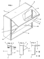
- the closure device according to the invention is fitted to a wall-mounted furniture unit in the form of a container indicated overall by 1 , and comprising a base 2, two side walls 3, a roof 4 and a rear wall 5.
- the container is closed by a pair of doors 6,6', of which the upper door 6 is hinged to the container 1 at the front edge of the roof 4, whereas the lower door 6 ' is hinged to the upper door 6 along their contacting edges, at which a hinge section element 7 is provided allowing mutual 180° rotation to pass from the coplanar configuration in which the furniture unit is closed (Figure 2) to the superposed configuration in which the furniture unit is open ( Figure 4).
- a section bar 8 preferably of plastics or metal construction is applied to the front vertical edge of each side wall 3 and comprises a rear rib 9 for fixing to the side wall 3, a front channel 10 in which a trolley 11 slides and is guided, and a side channel 12 in which the pivot 13 of a counterweight 14 extending horizontally from one side wall 3 to the other sides and is guided.
- the channels 10 and 12 are provided with longitudinal deformable approached lips (not shown in the drawings) ensuring the closure of the same channels when they are not engaged by the trolley 11 and the pivot 13 respectively.
- each channel 10 As statged, inside each channel 10 there: slides a trolley 11 provided with an appendix 15 to: which the lower door 6' is hinged in proximity to the corresponding lateral edge. To the upper end of each section bar 8 there is fitted a block 16 in which there is idly mounted a deviation pulley 17 for a cable 18 connected at one end to the corresponding trolley 1 1 and at its other end to the pivot 13 of the counterweight 14.
- An element 19 rigid with the upper door 6 is hinged to each block 16.
- the counterweight 14 consists of a horizontal cylindrical bar provided at its ends with the pivots 13 which slide in the lateral channel 12 of the section bars 8. In its central region the counterweight 14 is provided with a gripping lever 20 retained by a diametrical screw 21 of ferromagnetic material.
- the angular position of the screw 21 relative to the lever 20 is such that when the lever is in its most downwardly inclined position, ie resting against the front edge of the base 2 of the container 1, the screw 21 is perfectly vertical with its head facing downwards towards a magnet 22 fitted to the base 2 ( Figure 7).
- a handgrip 23 fitted to the door 6' is pulled slightly forwards sufficiently to displace the two doors 6,6' from their coplanar state. It is then possible to raise the lower door 6' so that it folds on to the door 6 because of their mutual connection and the connection between said door 6 and the container 1.
- the user grips the lever 20 and lift it. This initially rotates the counterweight 14 with consequent disengagement of the screw 21 from the magnet 22, followed by raising of the counterweight itself. As the counterweight rises, the two rolleys 11 connected thereto by the cables 18 descend and drag the lower door 6' which, being connected to the upper door 6, thus closes the furniture unit.
- the counterweight has risen to a height beyond the maximum reach of the user, the user continues the closure action by directly pulling the lower edge of the lower door 6' or handgrip 23.
- the completely closed configuration is stabilised by the actual weight of the two doors 6,6' and preferably by magnets 24 fitted to the section bars 8 and corresponding metal plastes 25 fitted to the lower door 6'.
- a pair of counterweights are provided, each applied to the cable of the corresponding section bar 8 and also operable from the outside.
Landscapes
- Engineering & Computer Science (AREA)
- Mechanical Engineering (AREA)
- Civil Engineering (AREA)
- Structural Engineering (AREA)
- Combinations Of Kitchen Furniture (AREA)
- Hinges (AREA)
- Wing Frames And Configurations (AREA)
- Securing Of Glass Panes Or The Like (AREA)
- Devices For Use In Laboratory Experiments (AREA)
- Cabinets, Racks, Or The Like Of Rigid Construction (AREA)
- Support Devices For Sliding Doors (AREA)
- Extensible Doors And Revolving Doors (AREA)
Priority Applications (1)
| Application Number | Priority Date | Filing Date | Title |
|---|---|---|---|
| AT86108528T ATE43673T1 (de) | 1985-07-01 | 1986-06-23 | Tuer fuer an der wand montierte moebel. |
Applications Claiming Priority (2)
| Application Number | Priority Date | Filing Date | Title |
|---|---|---|---|
| IT84128/85A IT1187447B (it) | 1985-07-01 | 1985-07-01 | Dispositivo di chiusura ad ante per mobili pensili |
| IT8412885 | 1985-07-01 |
Publications (2)
| Publication Number | Publication Date |
|---|---|
| EP0210431A1 true EP0210431A1 (de) | 1987-02-04 |
| EP0210431B1 EP0210431B1 (de) | 1989-05-31 |
Family
ID=11324442
Family Applications (1)
| Application Number | Title | Priority Date | Filing Date |
|---|---|---|---|
| EP86108528A Expired EP0210431B1 (de) | 1985-07-01 | 1986-06-23 | Tür für an der Wand montierte Möbel |
Country Status (5)
| Country | Link |
|---|---|
| EP (1) | EP0210431B1 (de) |
| JP (1) | JPS6210388A (de) |
| AT (1) | ATE43673T1 (de) |
| DE (1) | DE3663710D1 (de) |
| IT (1) | IT1187447B (de) |
Cited By (7)
| Publication number | Priority date | Publication date | Assignee | Title |
|---|---|---|---|---|
| GB2240574A (en) * | 1990-02-02 | 1991-08-07 | Nicholas Walter George Cole | Bifold door |
| DE29719623U1 (de) * | 1997-11-05 | 1997-12-18 | Kaufmann GmbH, 41515 Grevenbroich | Toranordnung für klimatisierte Bereiche |
| US6332660B1 (en) | 1998-05-06 | 2001-12-25 | Arturo Salice S.P.A. | Piece of furniture with a body part closeable by a two-wing folding sliding door |
| WO2013185885A1 (de) * | 2012-06-11 | 2013-12-19 | Grass Gmbh | Möbel und vorrichtung zum bewegen einer möbelklappe eines möbels |
| CN103742041A (zh) * | 2013-12-06 | 2014-04-23 | 谢雨珂 | 一种壁柜 |
| IT201600075104A1 (it) * | 2016-07-18 | 2018-01-18 | Convivio S R L | Sistema di movimentazione di ante di mobili a forza variabile |
| CN115425451A (zh) * | 2021-05-13 | 2022-12-02 | 深南电路股份有限公司 | 一种遮挡组件及其线缆适配器 |
Families Citing this family (2)
| Publication number | Priority date | Publication date | Assignee | Title |
|---|---|---|---|---|
| CN100396579C (zh) * | 2004-10-10 | 2008-06-25 | 中国国际海运集装箱(集团)股份有限公司 | 一种集装箱的门结构、其制作方法及采用该结构的集装箱 |
| FR2922226B1 (fr) * | 2007-10-12 | 2009-11-20 | Seb Sa | Fer a repasser comportant un dispositif guide cordon perfectionne. |
Citations (9)
| Publication number | Priority date | Publication date | Assignee | Title |
|---|---|---|---|---|
| US1716394A (en) * | 1927-12-02 | 1929-06-11 | El Paso Sash & Door Co | Door for kitchen cabinets |
| FR840510A (de) * | 1938-04-27 | |||
| CH256800A (de) * | 1947-08-27 | 1948-09-15 | F Biesser | Vorrichtung zum Heben und Senken von Schiebefenstern. |
| US2523929A (en) * | 1946-01-30 | 1950-09-26 | Donald G Taylor | Counter-balanced closure |
| FR1148606A (fr) * | 1956-03-02 | 1957-12-12 | Volet store pliant de bas en haut, métallique, à manoeuvre compensée | |
| US3317259A (en) * | 1965-06-03 | 1967-05-02 | Samuel S Otis | Cabinet construction |
| US3349829A (en) * | 1966-01-25 | 1967-10-31 | Panelfold Doors Inc | Track seal for folding doors |
| US3684341A (en) * | 1970-09-08 | 1972-08-15 | Weber Dental Mfg Co | Fold-away cover for dental drinking cup support |
| CH572149A5 (en) * | 1974-07-09 | 1976-01-30 | Frigerio Giuseppe | Wardrobe with balanced tilting door - has flat chamber for accommodating counterweight on end of a rope |
Family Cites Families (1)
| Publication number | Priority date | Publication date | Assignee | Title |
|---|---|---|---|---|
| JPS5352639U (de) * | 1976-10-08 | 1978-05-06 |
-
1985
- 1985-07-01 IT IT84128/85A patent/IT1187447B/it active
-
1986
- 1986-01-28 JP JP61016658A patent/JPS6210388A/ja active Granted
- 1986-06-23 DE DE8686108528T patent/DE3663710D1/de not_active Expired
- 1986-06-23 EP EP86108528A patent/EP0210431B1/de not_active Expired
- 1986-06-23 AT AT86108528T patent/ATE43673T1/de not_active IP Right Cessation
Patent Citations (9)
| Publication number | Priority date | Publication date | Assignee | Title |
|---|---|---|---|---|
| FR840510A (de) * | 1938-04-27 | |||
| US1716394A (en) * | 1927-12-02 | 1929-06-11 | El Paso Sash & Door Co | Door for kitchen cabinets |
| US2523929A (en) * | 1946-01-30 | 1950-09-26 | Donald G Taylor | Counter-balanced closure |
| CH256800A (de) * | 1947-08-27 | 1948-09-15 | F Biesser | Vorrichtung zum Heben und Senken von Schiebefenstern. |
| FR1148606A (fr) * | 1956-03-02 | 1957-12-12 | Volet store pliant de bas en haut, métallique, à manoeuvre compensée | |
| US3317259A (en) * | 1965-06-03 | 1967-05-02 | Samuel S Otis | Cabinet construction |
| US3349829A (en) * | 1966-01-25 | 1967-10-31 | Panelfold Doors Inc | Track seal for folding doors |
| US3684341A (en) * | 1970-09-08 | 1972-08-15 | Weber Dental Mfg Co | Fold-away cover for dental drinking cup support |
| CH572149A5 (en) * | 1974-07-09 | 1976-01-30 | Frigerio Giuseppe | Wardrobe with balanced tilting door - has flat chamber for accommodating counterweight on end of a rope |
Cited By (9)
| Publication number | Priority date | Publication date | Assignee | Title |
|---|---|---|---|---|
| GB2240574A (en) * | 1990-02-02 | 1991-08-07 | Nicholas Walter George Cole | Bifold door |
| DE29719623U1 (de) * | 1997-11-05 | 1997-12-18 | Kaufmann GmbH, 41515 Grevenbroich | Toranordnung für klimatisierte Bereiche |
| US6332660B1 (en) | 1998-05-06 | 2001-12-25 | Arturo Salice S.P.A. | Piece of furniture with a body part closeable by a two-wing folding sliding door |
| EP0955436A3 (de) * | 1998-05-06 | 2002-07-17 | Arturo Salice S.p.A. | Möbel mit einem durch eine zweiflügelige Faltschiebetür verschliessbaren Korpusteil |
| WO2013185885A1 (de) * | 2012-06-11 | 2013-12-19 | Grass Gmbh | Möbel und vorrichtung zum bewegen einer möbelklappe eines möbels |
| CN103742041A (zh) * | 2013-12-06 | 2014-04-23 | 谢雨珂 | 一种壁柜 |
| IT201600075104A1 (it) * | 2016-07-18 | 2018-01-18 | Convivio S R L | Sistema di movimentazione di ante di mobili a forza variabile |
| EP3272982A1 (de) * | 2016-07-18 | 2018-01-24 | CONVIVIO S.r.l. | Vorrichtung zum bewegen von möbelklappen mit variabler kraft |
| CN115425451A (zh) * | 2021-05-13 | 2022-12-02 | 深南电路股份有限公司 | 一种遮挡组件及其线缆适配器 |
Also Published As
| Publication number | Publication date |
|---|---|
| JPS6210388A (ja) | 1987-01-19 |
| JPH0458550B2 (de) | 1992-09-17 |
| ATE43673T1 (de) | 1989-06-15 |
| DE3663710D1 (en) | 1989-07-06 |
| IT1187447B (it) | 1987-12-23 |
| EP0210431B1 (de) | 1989-05-31 |
| IT8584128A0 (it) | 1985-07-01 |
Similar Documents
| Publication | Publication Date | Title |
|---|---|---|
| US4379478A (en) | Folding overhead doors | |
| US4568132A (en) | Motorized lift mechanism | |
| EP0210431B1 (de) | Tür für an der Wand montierte Möbel | |
| JP6064244B2 (ja) | 特に自動車庫用のセクション式ドア | |
| US20180128032A1 (en) | Piece of Furniture, in Particular a Cabinet Unit | |
| US5820233A (en) | Cabinet for displaying objects | |
| EP0841459A3 (de) | Aufgehängter Lagerschrank | |
| EP0382435B1 (de) | Vorrichtung mit zwei sich auseinanderbewegenden Läden | |
| ES2291003T3 (es) | Cierre para aberturas de todo tipo, preferentemente para muebles. | |
| KR102367050B1 (ko) | 모니터의 수납이 가능한 책상 | |
| CN211354441U (zh) | 一种间距可调的定制用升降型衣柜 | |
| JP2002095534A (ja) | 扉付き昇降キャビネット | |
| EP1555369A1 (de) | Schiebetür | |
| US2009348A (en) | Counterbalanced garage door | |
| KR102833725B1 (ko) | 반자동형 슬라이딩 도어 시스템 | |
| JPH0516390Y2 (de) | ||
| US4850417A (en) | Bendable multiple window | |
| CN214997180U (zh) | 一种简易的防夹手自动门 | |
| NL2007866C2 (nl) | Systeem en werkwijze voor het aanbieden van een object. | |
| JP2579288B2 (ja) | 横引障子の移動収納装置 | |
| US2458604A (en) | Garage door | |
| GB2034790A (en) | Bi-panel overhead garage door | |
| JPH0238979Y2 (de) | ||
| JPH0737027Y2 (ja) | 上げ下げ窓 | |
| JPH0737028Y2 (ja) | 上げ下げ窓 |
Legal Events
| Date | Code | Title | Description |
|---|---|---|---|
| PUAI | Public reference made under article 153(3) epc to a published international application that has entered the european phase |
Free format text: ORIGINAL CODE: 0009012 |
|
| AK | Designated contracting states |
Kind code of ref document: A1 Designated state(s): AT BE CH DE FR GB IT LI LU NL SE |
|
| 17P | Request for examination filed |
Effective date: 19870804 |
|
| 17Q | First examination report despatched |
Effective date: 19880812 |
|
| GRAA | (expected) grant |
Free format text: ORIGINAL CODE: 0009210 |
|
| ITF | It: translation for a ep patent filed | ||
| AK | Designated contracting states |
Kind code of ref document: B1 Designated state(s): AT BE CH DE FR GB IT LI LU NL SE |
|
| PG25 | Lapsed in a contracting state [announced via postgrant information from national office to epo] |
Ref country code: SE Effective date: 19890531 Ref country code: AT Effective date: 19890531 |
|
| REF | Corresponds to: |
Ref document number: 43673 Country of ref document: AT Date of ref document: 19890615 Kind code of ref document: T |
|
| REF | Corresponds to: |
Ref document number: 3663710 Country of ref document: DE Date of ref document: 19890706 |
|
| ET | Fr: translation filed | ||
| PLBE | No opposition filed within time limit |
Free format text: ORIGINAL CODE: 0009261 |
|
| STAA | Information on the status of an ep patent application or granted ep patent |
Free format text: STATUS: NO OPPOSITION FILED WITHIN TIME LIMIT |
|
| 26N | No opposition filed | ||
| PGFP | Annual fee paid to national office [announced via postgrant information from national office to epo] |
Ref country code: GB Payment date: 19940621 Year of fee payment: 9 |
|
| PGFP | Annual fee paid to national office [announced via postgrant information from national office to epo] |
Ref country code: FR Payment date: 19940627 Year of fee payment: 9 Ref country code: CH Payment date: 19940627 Year of fee payment: 9 |
|
| PGFP | Annual fee paid to national office [announced via postgrant information from national office to epo] |
Ref country code: NL Payment date: 19940630 Year of fee payment: 9 Ref country code: LU Payment date: 19940630 Year of fee payment: 9 Ref country code: BE Payment date: 19940630 Year of fee payment: 9 |
|
| EPTA | Lu: last paid annual fee | ||
| PG25 | Lapsed in a contracting state [announced via postgrant information from national office to epo] |
Ref country code: LU Free format text: LAPSE BECAUSE OF NON-PAYMENT OF DUE FEES Effective date: 19950623 Ref country code: GB Effective date: 19950623 |
|
| PG25 | Lapsed in a contracting state [announced via postgrant information from national office to epo] |
Ref country code: LI Effective date: 19950630 Ref country code: CH Effective date: 19950630 Ref country code: BE Effective date: 19950630 |
|
| BERE | Be: lapsed |
Owner name: KAIROS S.N.C. DI M.BONETTI G.MANENTE E A.MION ING Effective date: 19950630 |
|
| PG25 | Lapsed in a contracting state [announced via postgrant information from national office to epo] |
Ref country code: NL Effective date: 19960101 |
|
| GBPC | Gb: european patent ceased through non-payment of renewal fee |
Effective date: 19950623 |
|
| PG25 | Lapsed in a contracting state [announced via postgrant information from national office to epo] |
Ref country code: FR Effective date: 19960229 |
|
| REG | Reference to a national code |
Ref country code: CH Ref legal event code: PL |
|
| NLV4 | Nl: lapsed or anulled due to non-payment of the annual fee |
Effective date: 19960101 |
|
| REG | Reference to a national code |
Ref country code: FR Ref legal event code: ST |
|
| PGFP | Annual fee paid to national office [announced via postgrant information from national office to epo] |
Ref country code: IT Payment date: 20050624 Year of fee payment: 20 |
|
| PGFP | Annual fee paid to national office [announced via postgrant information from national office to epo] |
Ref country code: DE Payment date: 20050825 Year of fee payment: 20 |