EP0210549A2 - Appareil pour l'application de joints toriques sur des pièces - Google Patents
Appareil pour l'application de joints toriques sur des pièces Download PDFInfo
- Publication number
- EP0210549A2 EP0210549A2 EP86109808A EP86109808A EP0210549A2 EP 0210549 A2 EP0210549 A2 EP 0210549A2 EP 86109808 A EP86109808 A EP 86109808A EP 86109808 A EP86109808 A EP 86109808A EP 0210549 A2 EP0210549 A2 EP 0210549A2
- Authority
- EP
- European Patent Office
- Prior art keywords
- receiving element
- ring
- spreading
- axis
- tool
- Prior art date
- Legal status (The legal status is an assumption and is not a legal conclusion. Google has not performed a legal analysis and makes no representation as to the accuracy of the status listed.)
- Withdrawn
Links
- 238000003892 spreading Methods 0.000 claims abstract description 69
- 230000002093 peripheral effect Effects 0.000 description 5
- 230000006835 compression Effects 0.000 description 4
- 238000007906 compression Methods 0.000 description 4
- 238000005096 rolling process Methods 0.000 description 4
- 239000000463 material Substances 0.000 description 3
- 230000005489 elastic deformation Effects 0.000 description 2
- 238000007789 sealing Methods 0.000 description 2
- 230000005540 biological transmission Effects 0.000 description 1
- 238000010276 construction Methods 0.000 description 1
- 230000008878 coupling Effects 0.000 description 1
- 238000010168 coupling process Methods 0.000 description 1
- 238000005859 coupling reaction Methods 0.000 description 1
- 230000001419 dependent effect Effects 0.000 description 1
- 238000011161 development Methods 0.000 description 1
- 230000018109 developmental process Effects 0.000 description 1
- 238000006073 displacement reaction Methods 0.000 description 1
- 239000013013 elastic material Substances 0.000 description 1
- 230000009191 jumping Effects 0.000 description 1
- 238000004519 manufacturing process Methods 0.000 description 1
- 238000003860 storage Methods 0.000 description 1
Images

Classifications
-
- B—PERFORMING OPERATIONS; TRANSPORTING
- B23—MACHINE TOOLS; METAL-WORKING NOT OTHERWISE PROVIDED FOR
- B23P—METAL-WORKING NOT OTHERWISE PROVIDED FOR; COMBINED OPERATIONS; UNIVERSAL MACHINE TOOLS
- B23P19/00—Machines for simply fitting together or separating metal parts or objects, or metal and non-metal parts, whether or not involving some deformation; Tools or devices therefor so far as not provided for in other classes
- B23P19/04—Machines for simply fitting together or separating metal parts or objects, or metal and non-metal parts, whether or not involving some deformation; Tools or devices therefor so far as not provided for in other classes for assembling or disassembling parts
- B23P19/08—Machines for placing washers, circlips, or the like on bolts or other members
- B23P19/084—Machines for placing washers, circlips, or the like on bolts or other members for placing resilient or flexible rings, e.g. O-rings, circlips
-
- Y—GENERAL TAGGING OF NEW TECHNOLOGICAL DEVELOPMENTS; GENERAL TAGGING OF CROSS-SECTIONAL TECHNOLOGIES SPANNING OVER SEVERAL SECTIONS OF THE IPC; TECHNICAL SUBJECTS COVERED BY FORMER USPC CROSS-REFERENCE ART COLLECTIONS [XRACs] AND DIGESTS
- Y10—TECHNICAL SUBJECTS COVERED BY FORMER USPC
- Y10T—TECHNICAL SUBJECTS COVERED BY FORMER US CLASSIFICATION
- Y10T29/00—Metal working
- Y10T29/53—Means to assemble or disassemble
- Y10T29/53657—Means to assemble or disassemble to apply or remove a resilient article [e.g., tube, sleeve, etc.]
Definitions
- the invention relates to a device for applying O-rings to workpieces, in particular cylindrical workpieces according to the preamble of claim 1.
- O-rings which are generally used as sealing rings and which are made of rubber or other elastic material, to workpieces. So that these rings can reliably fulfill their later function (e.g. as sealing rings), it is necessary to apply the rings as gently as possible, i.e. especially to avoid overstretching the rings during application.
- the invention has for its object to provide a device that enables automatic, gentle application of O-rings on workpieces, while at the same time effectively prevents the O-rings from rolling on the surface of the workpiece in question when it is applied or pushed on.
- the O-ring to be applied to a workpiece is first fed to the expanding tool, which together with the transfer tool forms the two essential functional elements of the device, in such a way that the expanding elements in the rest position lie with their contact surfaces in the opening of the O-ring.
- the spreading elements are then moved into their working position, whereby the O-ring lying on the first contact surfaces of the spreading elements is stretched by elastic deformation of its material, but not beyond a permissible or exceeding the elastic limits.
- the O-ring thus stretched is then transferred to the transfer tool in such a way that the inner surface of the O-ring, which is still stretched, bears against the second contact surfaces formed by the segments of the receiving element of the transfer tool.
- the transfer takes place so that after the O-ring is spread by the spreading elements, the spreading tool and the transfer tool are guided into one another in the direction of the first or second axis such that each first contact surface of the spreading elements of the spreading tool in the working position between two adjacent segments of the receiving element of the transfer tool, wherein in this positioning (second position) of the spreading tool and the transfer tool which characterizes the transfer situation, the second contact surfaces are preferably located somewhat radially within the first contact surfaces, so that the segments of the transfer tool or those formed by these segments are inserted second contact surfaces in the opening of the spread O-ring is possible without touching this ring.
- the receiving element is pushed onto this workpiece or, conversely, the workpiece is pushed into the receiving element, in both cases in such a way that the end of the receiving element is immediately adjacent to the location of the workpiece the (location) of the O-ring is to be put on.
- the O-ring is then pressed down from the receiving element, the O-ring only jumping over the edge at the end of the receiving element onto the workpiece, so that it does not roll on a surface during this transmission or can roll.
- the device according to the invention has the particular advantage that the receiving element or the part of this receiving element which has the segments can be made very thin-walled, since the receiving element is supplied with the O-rings which have already been spread or stretched by the expanding tool.
- the thin-walled design of the receiving element makes it possible, above all, to keep the stretch required for applying an O-ring to a workpiece small.
- 1 is a workpiece in the form of a shaft, to which (shaft) an O-ring 2, for example serving as a seal, made of rubber or rubber-like material is to be applied in such a way that this O-ring, after application, has its axis aligned with the axis
- the axis of the shaft 1 lies and is partially received by an annular groove provided in the peripheral surface of the shaft 1, as is shown in FIG. 9.
- a device which essentially consists of an expanding tool 3 and a transfer tool 4 (FIG. 8) is used to apply the O-ring 2 to the shaft 1.
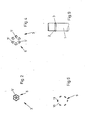
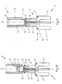
- the essential elements of these tools and their function are shown in Figures 1 to 7.
- the spreading tool 3 has six spreading arms 5, which are arranged evenly distributed around an axis A and lie with their longitudinal extension in the direction of this axis.
- Each spreader arm 5 is pivotally mounted in its central region with the aid of a hinge pin 6 in a support element 7 (FIG. 8) common to all spreader arms 5, the axis of the hinge pin 6 of each spreader arm 5 being perpendicular to the axis A and perpendicular to one radial to the same Axis extending line lies.
- the lengths 5 'of the spreader arms 5 lying above the hinge pin 6 in FIGS. 1 and 3 are curved on their outer surface in a convex or circular arc such that these outer surfaces of all the spreader arms or lengths 5' when the spreader tool 3 or spreader arms 5 are in the working position ( 3 and 4) lie on a common circular line running concentrically to the axis A.
- the spreading arms 5 are further provided in the region of the length 5 'with a web-like projection 8 which extends in the direction of the longitudinal extent of the associated spreading arm 5 or its length 5', each projection 8 with its in the Fig 1 and 3 ends at a distance from the upper end of the length 5 'of the associated spreader arm 5 and thus form a vertical storage surface for the O-ring 2 which is gripped or spread by the spreader arms 5.
- the area of the convexly curved outer surface of each spreader arm 5 or its length 5 ′, which is free from the projection 8, forms a contact surface against which the O-ring 2 received or spread by the spreader tool has its inner surface is present.
- the transfer tool has a receiving element 9, which is designed as a thin-walled tube piece with a circular outer or peripheral surface and with a likewise circular inner surface.
- the receiving element 9 On its outer surface, the receiving element 9 has a cross section that is approximately the same or is slightly smaller than the diameter of the circular line on which the outer surfaces of the upper ends of the spreading arms 5, ie the contact surfaces of these spreading arms are arranged when the spreading arms are in the working position.
- the receiving element is at one end, i.e. in the illustration chosen for FIG. 5, at the lower end with recesses 10 extending in the direction of the axis B of this element, which are open towards this end of the receiving element.
- the number of recesses 10 is chosen so that at the lower end of the receiving element between the recesses six each from the peripheral wall of a hollow cylinder, ie. segments 11 formed from the respectively remaining part of the peripheral wall of the tubular receiving element, which together form with their outer surface an annular contact surface interrupted in the area of the recesses 10, against which the O-ring 2 transferred to the transfer element bears with its inner surface. Due to the recesses 10 and 10 and the segments 11, the receiving element is crown-like at its lower end.
- the segments 11 or the recesses 10 forming these segments are further arranged and designed such that, when the spreading arms 5 are in the working position, there is space for a segment 11 between two adjacent spreading arms and the spreading arms 5 with the upper end of their lengths 5 'in each case Recess 10 find space or can protrude slightly radially outwards with the outer peripheral surfaces formed at the upper end slightly beyond the second contact surface formed by the outer surface of the segments 11, if, as shown in FIG. 5, the two tools with their axes A or B are arranged axially and are moved relative to each other in the transfer position.
- a sleeve-like slide 12 is arranged, which forms with its end face adjacent to the lower end of the receiving element 9 a further contact surface 13, which are otherwise bevelled or frustoconical in such a way that the radially inner Area of this contact surface 13 is closer in the lower end than the radially outer area.
- the contact surface 13 is arranged in the rest position of the slide 12 at a distance from the lower end of the receiving element 9 and which can be displaced from this rest position at least to the extent that the contact surface 13 lies at the same level as the lower end of the receiving element 9 the O-ring 2 held on the segments 11 can be pushed onto the workpiece or onto the shaft 1, as will be explained in more detail below, the beveling of the contact surface 13 preventing the O-ring 2 from being pushed on the workpiece or on the shaft 1 rotates or rolls on the workpiece.
- the tubular receiving element 9 is formed by the lower end of a rod 15 with a circular bore having a blind bore 14.
- An O-ring 2 is applied to the shaft 1 with the device shown in principle in FIGS. 1 to 7 in the following way:
- the O-ring 2 is first brought with the aid of a feed device in the area of the spreading tool 3 such that the O-ring 2 lies with its ring surface perpendicular to the axis A of the spreading tool 3, the spreading arms of which are shown in that of FIG. 1 Rest position. If the O-ring 2 is not fed directly to the spreading tool 3 so that the spreading arms 5 extend into the opening of the O-ring 2 with their first contact surface formed at the upper end of the lengths 5 ', this becomes after the O-ring has been fed 2 reached in the effective range of the expanding tool 3 by a corresponding movement of this tool.
- the transfer tool 4 is now in a position in which the receiving element 9 lies with its axis B coaxially with the axis A, but the lower end of the receiving element 9 is still arranged at a distance from the upper end of the spreading arms 5 or their lengths 5 ' is.
- the spreading tool 3 or the part of this spreading tool which has the spreading arms 5 and the receiving element 9 together with the slider 12 seated thereon are moved relative to one another in the direction of the axes A or B such that each segment formed at the lower end of the receiving element 9 11 enters from above into the space between two lengths 5 'of the spreading arms 5 in the working position or, conversely, each length 5' of the spreading arms 5 in the working position enters from below into a recess 10 of the receiving element 9.
- the spreading tool 3 and the transfer tool 4 are then moved apart relative to one another in the direction of the axes A and B, respectively. Subsequently, the receiving element 9 together with the slide 12 and with the spread O-ring held at the lower end of the receiving element is pushed onto the shaft 1 by a pivoting or rotating movement with subsequent movement in the direction of arrow B, so that the lower end of the Receiving element 9 is located directly adjacent to the groove provided in the shaft 1, into which the O-ring 2 is to be inserted.
- the device described in its structure and function in principle in connection with FIGS. 1 to 7 allows the O-ring 2 to be applied very gently to the shaft 1 in a completely mechanized manner, in particular also without the risk of the O-ring being overstretched 2 and without the risk that the O-ring 2 will roll when it is applied to the shaft 1 on its circumferential surface and thus twisted or twisted in the groove of the shaft 1 in an undesired manner. Both would significantly impair the proper functioning of the O-ring, for example as a seal.
- the tubular design of the receiving element 9 means that it can be pushed onto the shaft 1 to the extent that the O-ring 2 seated at the outermost lower end of the receiving element 9 or the segments 11 with the aid of the a rolling of this ring on the segments 11 preventing inclined contact surface 13 only has to be shifted by a very small amount in order to get into or jump into the annular groove of the shaft 1 lying directly at the free end of the segments 11.
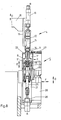
- FIG. 8 The device is shown in more detail in FIG. 8.
- FIG. 8 is the one end of a support arm extending in the horizontal direction, which in the vertical direction, i.e. can be moved up and down in the direction parallel to the axis B of the receiving element 9 formed by the lower end of the rod 15, as indicated by the double arrow D.
- a circuit board 17 is fastened, which on the one hand carries a pneumatically operable piston-cylinder device 18 and on the other hand the rod 15.
- the spreading tool 3 consists essentially of a device part composed of a plurality of elements 19, 20 and 21, of which the element 19 is designed as a sleeve-like body with a cross section narrowing towards the lower end, in which the support element 7 is displaceable in the direction of the axis A. is arranged.
- the support element 7 consists of a plurality of segments 7 'fastened to a plate 22 on the upper side, a spreading arm 5 being pivotably mounted between the two segments 7' with the aid of the joint pin 6.
- a roller 23 is provided on each spreader arm 5, which abuts against the inner surface of the element 9 designed as a sleeve.
- each spreader arm 5 is assigned a compression spring 24, which acts with one end on the lower length 5 ′′ of the spreader arm 5 in question and biases it into its rest position (FIG. 1). All compression springs 24 are supported with the other end in the central region of the support element 7. Via a coupling rod 25, the axis of which lies coaxially with the axis A of the spreading tool 3, the support element 7 with the piston of a pneumatically actuated piston-cylinder device 26 connected, which is held at the lower end of the element 21 designed as an angled arm.
- the support element 7 can thus be pushed back and forth relative to the element 19 designed as a sleeve in the direction of the axis A, as indicated by the double arrow E, with the support element 7 being moved downward the rollers 23 come into contact with the inner surface of the section of the element 19 which is narrowed in cross section and thereby pivot the spreading arms 5 or their upper lengths 5 'radially outward against the action of the compression springs 24 into their working position.
- This working position is reached when the plate 22, which has an opening in its central region through which the upper ends of the spreading arms 5 project outwards, rests with its underside against the upper edge of the element 19 designed as a sleeve.
- the O-rings 2 to be applied to the workpiece or to the shaft 1 are fed via a conveyor device 27 designed as a linear conveyor, with the first O-ring 2 at the end of this conveyor device 27 in the conveying direction the upper ends of the lengths 5 'of the spreading arms 5 which are in the rest position are placed or applied.
- This can be done either with the aid of a gripping or transfer device shown in FIG. 8, or, for example, in that the entire spreading tool 3 is movably guided on the machine frame 28 in the horizontal direction and in the vertical direction, as indicated by the double arrows F.
- the transfer tool 4 is lowered in the direction of arrow D, so that the segments 11 formed at the lower end of the receiving element 9 in the manner already described above into the gaps 5 formed between the upper lengths 5 'of the spreading arms 5 in the working position thus insert it into the openings of the spread O-ring 2.
- the arm having the end 16 can be pivoted together with the transfer tool 4, for example, about a vertical axis into a position in which the Receiving element 9 is located above the workpiece (shaft 1) then lying coaxially with axis B, so that first by lowering the entire transfer tool 4 or by pushing the receiving element 9 onto the shaft 1 and then pushing the slide 12 (by actuating the piston Cylinder device 18) the O-ring is introduced into the groove of the shaft 1 in the manner already described above.
- the slide 12 has an annular contact surface 13 'which, in contrast to the contact surface 13, is not beveled, but lies in a plane perpendicular to the axis B. This design is possible if there is no fear of the O-ring 2 rolling off when it is pushed onto the workpiece, given the corresponding surface condition of the workpiece.
Landscapes
- Engineering & Computer Science (AREA)
- Mechanical Engineering (AREA)
- Automatic Assembly (AREA)
- Coating Apparatus (AREA)
Applications Claiming Priority (4)
| Application Number | Priority Date | Filing Date | Title |
|---|---|---|---|
| DE3526081 | 1985-07-20 | ||
| DE3526081 | 1985-07-20 | ||
| DE19853526768 DE3526768A1 (de) | 1985-07-20 | 1985-07-26 | Vorrichtung zum aufbringen von o-ringen auf werkstuecke |
| DE3526768 | 1985-07-26 |
Publications (2)
| Publication Number | Publication Date |
|---|---|
| EP0210549A2 true EP0210549A2 (fr) | 1987-02-04 |
| EP0210549A3 EP0210549A3 (fr) | 1989-03-01 |
Family
ID=25834225
Family Applications (1)
| Application Number | Title | Priority Date | Filing Date |
|---|---|---|---|
| EP86109808A Withdrawn EP0210549A3 (fr) | 1985-07-20 | 1986-07-17 | Appareil pour l'application de joints toriques sur des pièces |
Country Status (4)
| Country | Link |
|---|---|
| US (1) | US4703548A (fr) |
| EP (1) | EP0210549A3 (fr) |
| CA (1) | CA1260680A (fr) |
| DE (1) | DE3526768A1 (fr) |
Cited By (1)
| Publication number | Priority date | Publication date | Assignee | Title |
|---|---|---|---|---|
| GB2206833A (en) * | 1987-07-03 | 1989-01-18 | John Charles Payne | Washer positioning device |
Families Citing this family (21)
| Publication number | Priority date | Publication date | Assignee | Title |
|---|---|---|---|---|
| DE3602867A1 (de) * | 1986-01-31 | 1987-08-06 | Uni Cardan Ag | Vorrichtung und verfahren zur montage eines faltenbalges |
| DE3812741A1 (de) * | 1988-04-16 | 1989-10-26 | Seeger Orbis Gmbh | Einbaugeraet fuer sicherungsringe |
| DE3816593A1 (de) * | 1988-05-16 | 1989-11-23 | Coelestin Dipl Ing Ohrmann | Verfahren und vorrichtung zur automatischen montage von dichtringen |
| DE3822809A1 (de) * | 1988-07-06 | 1990-01-18 | Mertens Peter | Robotergreifer zur aussenmontage biegeschlaffer teile |
| DE4135721C1 (en) * | 1991-10-30 | 1992-11-05 | Josef 7414 Lichtenstein De Krista | Method of mounting O=rings - has O=rings orientated for positioning with hollow mandrel |
| DE4214845C2 (de) * | 1992-05-05 | 1999-04-08 | Walter Dipl Ing Nikolaus | Vorrichtung zum Aufbringen weitungsfähiger elastischer Ringe |
| JPH078990U (ja) * | 1993-07-13 | 1995-02-07 | 住友電装株式会社 | インサート端子の成形装置 |
| JP3908844B2 (ja) * | 1998-01-20 | 2007-04-25 | サントリー株式会社 | シールリングの組込方法およびその装置 |
| DE10022383C2 (de) * | 2000-05-08 | 2003-10-02 | Guenther Schulz | Vorrichtung zum Aufziehen von Dichtungsringen auf Rohrenden |
| DE10204733A1 (de) * | 2002-02-06 | 2003-08-14 | Koeberlein Gmbh | Montagevorrichtung zum Einschieben elastischer O-Ringe in Innennuten von Werkstücken |
| TW534087U (en) * | 2002-08-15 | 2003-05-21 | Silitek Corp | Device for fitting plastic ring |
| US6993816B2 (en) * | 2003-12-17 | 2006-02-07 | Smalley Steel Ring Company | Retaining ring installation tool |
| DE102006044748B4 (de) * | 2006-09-20 | 2018-02-15 | Ohrmann Gmbh Montagetechnik | Verfahren und Vorrichtung zur automatischen Montage von Dichtringen |
| USD671810S1 (en) * | 2012-02-20 | 2012-12-04 | Rocky Mountain Prestress, LLC | Strand chuck O-ring tool |
| DE102012211889A1 (de) * | 2012-07-09 | 2014-01-09 | Mahle International Gmbh | Montageverfahren und Montageeinrichtung |
| CN104552146A (zh) * | 2014-12-30 | 2015-04-29 | 建新赵氏集团有限公司 | 一种胶管隔离环安装装置 |
| DE102017221380A1 (de) * | 2017-11-29 | 2019-05-29 | Zf Friedrichshafen Ag | Einsetzvorrichtung zum Einsetzen eines Sicherungsrings in eine Nut, Montageanordnung mit der Einsetzvorrichtung und Verfahren zum Einsetzen eines Sicherungsrings mit der Montageanordnung |
| JP7298170B2 (ja) * | 2019-02-05 | 2023-06-27 | 株式会社デンソー | 組付け装置 |
| DE102019107346B4 (de) | 2019-03-22 | 2023-04-13 | Thomas Magnete GmbH | Filter zur Anwendung bei Ventilen zum Schutz vor Partikeln und Verfahren zum Zusammenbau einer Ventilhülse mit einem Filter |
| US12343830B2 (en) | 2021-08-26 | 2025-07-01 | Steven Lombardo | Automatic seal applicator apparatus and methods of using the same |
| DE102023108023A1 (de) | 2023-03-29 | 2024-10-02 | Wittenstein Se | Montagehilfe für O-Ringe |
Family Cites Families (5)
| Publication number | Priority date | Publication date | Assignee | Title |
|---|---|---|---|---|
| US3289286A (en) * | 1964-01-30 | 1966-12-06 | Henry W Allen | Omicron-ring seating tool |
| US3605239A (en) * | 1969-01-18 | 1971-09-20 | Dick Gordon Rockwell | Apparatus for external installation of resilient seals |
| DE2640835C2 (de) * | 1976-09-10 | 1978-10-12 | Maschinenfabrik Seidl Kg, 8000 Muenchen | Vorrichtung zum Abstreifen von axial nebeneinander in Ringnuten am Außenumfang eines Formkernes liegenden elastischen Ringen |
| GB1559211A (en) * | 1978-02-07 | 1980-01-16 | Armitage Shanks Group Ltd | Method of assembling an 'o' ring on a cylindrical component and apparatus therefor |
| AT389483B (de) * | 1983-04-21 | 1989-12-11 | Sticht Fertigungstech Stiwa | Verfahren und vorrichtung zum einsetzen von elastischen ringen in ringfoermige nuten |
-
1985
- 1985-07-26 DE DE19853526768 patent/DE3526768A1/de not_active Ceased
-
1986
- 1986-07-11 CA CA000513613A patent/CA1260680A/fr not_active Expired
- 1986-07-14 US US06/885,472 patent/US4703548A/en not_active Expired - Fee Related
- 1986-07-17 EP EP86109808A patent/EP0210549A3/fr not_active Withdrawn
Cited By (2)
| Publication number | Priority date | Publication date | Assignee | Title |
|---|---|---|---|---|
| GB2206833A (en) * | 1987-07-03 | 1989-01-18 | John Charles Payne | Washer positioning device |
| GB2206833B (en) * | 1987-07-03 | 1991-11-06 | John Charles Payne | Washer mounting or positioning device |
Also Published As
| Publication number | Publication date |
|---|---|
| EP0210549A3 (fr) | 1989-03-01 |
| US4703548A (en) | 1987-11-03 |
| CA1260680A (fr) | 1989-09-26 |
| DE3526768A1 (de) | 1987-01-29 |
Similar Documents
| Publication | Publication Date | Title |
|---|---|---|
| DE3526768A1 (de) | Vorrichtung zum aufbringen von o-ringen auf werkstuecke | |
| EP0452791B1 (fr) | Outil de pressage | |
| DE3201013A1 (de) | Schwenkspanner | |
| CH636573A5 (de) | Spannstuetze fuer papierrollen. | |
| DE2511988A1 (de) | Halter fuer rohrfoermige koerper | |
| WO2005066522A1 (fr) | Systeme et procede pour produire un arbre a cames | |
| DE102022101803A1 (de) | Montagewerkzeug zur Dichtungsringmontage | |
| DE1242981B (de) | Nietpistole | |
| CH663169A5 (de) | Verfahren und vorrichtung zum einsetzen von elastischen ringen in ringfoermige nuten. | |
| DE2801249C2 (de) | Entgratungsvorrichtung in einer auf einem zu entgratenden Schienenstrang geführten Stumpfschweißmaschine | |
| DE3319228C2 (fr) | ||
| DE2812086C3 (de) | Vorrichtung zum Befestigen eines Metallklemmbandes um einen mit einer Hülse versehenen zylindrischen Körper | |
| DE2221050A1 (de) | Sickenmaschine | |
| DE60038654T2 (de) | Klemmhalterung für Stütz- und Verbindungselemente | |
| DE2434859C3 (de) | Spannvorrichtung zum Spannen eines Werkstückes | |
| DE19703354C1 (de) | Spannvorrichtung zum Spannen zweier voneinander lösbarer Maschinenteile, insbesondere zum Festspannen eines Werkzeuges oder Werkstückes an einer Bearbeitungsmaschine | |
| DE69317128T2 (de) | Motorangetriebener greifer mit zwei greiferbacken | |
| WO2016062515A1 (fr) | Outil de pressage | |
| DE3908864C2 (de) | Vorrichtung zum Anbringen einer Manschette an einer Welle | |
| DE1299409B (de) | Werkzeug zum Einpressen einer starren Innenhuelse in die Bohrung eines von einer starren Aussenhuelse umschlossenen elastischen Ringkoerpers | |
| DE19504968A1 (de) | Spreizwerkzeug für Kaltverformungen | |
| DE1806665C3 (de) | Verfahren und Vorrichtung zum Befestigen von Muffen aus Metall an gerippten Bewehrungsstäben und nach dem Verfahren hergestellte Stoßverbindung | |
| EP0734815B1 (fr) | Outils pour Ôter des paliers | |
| DE3318994C1 (de) | Abrolleinrichtung | |
| DE4214845C2 (de) | Vorrichtung zum Aufbringen weitungsfähiger elastischer Ringe |
Legal Events
| Date | Code | Title | Description |
|---|---|---|---|
| PUAI | Public reference made under article 153(3) epc to a published international application that has entered the european phase |
Free format text: ORIGINAL CODE: 0009012 |
|
| AK | Designated contracting states |
Kind code of ref document: A2 Designated state(s): AT BE CH DE FR GB IT LI LU NL SE |
|
| PUAL | Search report despatched |
Free format text: ORIGINAL CODE: 0009013 |
|
| AK | Designated contracting states |
Kind code of ref document: A3 Designated state(s): AT BE CH DE FR GB IT LI LU NL SE |
|
| 17P | Request for examination filed |
Effective date: 19890829 |
|
| 17Q | First examination report despatched |
Effective date: 19901022 |
|
| STAA | Information on the status of an ep patent application or granted ep patent |
Free format text: STATUS: THE APPLICATION IS DEEMED TO BE WITHDRAWN |
|
| 18D | Application deemed to be withdrawn |
Effective date: 19910611 |