EP0210601A2 - Zylinderkopf für eine Brennkraftmaschine - Google Patents
Zylinderkopf für eine Brennkraftmaschine Download PDFInfo
- Publication number
- EP0210601A2 EP0210601A2 EP86110188A EP86110188A EP0210601A2 EP 0210601 A2 EP0210601 A2 EP 0210601A2 EP 86110188 A EP86110188 A EP 86110188A EP 86110188 A EP86110188 A EP 86110188A EP 0210601 A2 EP0210601 A2 EP 0210601A2
- Authority
- EP
- European Patent Office
- Prior art keywords
- head
- copper
- cylinder head
- cylinder
- insert
- Prior art date
- Legal status (The legal status is an assumption and is not a legal conclusion. Google has not performed a legal analysis and makes no representation as to the accuracy of the status listed.)
- Withdrawn
Links
Images


Classifications
-
- F—MECHANICAL ENGINEERING; LIGHTING; HEATING; WEAPONS; BLASTING
- F02—COMBUSTION ENGINES; HOT-GAS OR COMBUSTION-PRODUCT ENGINE PLANTS
- F02F—CYLINDERS, PISTONS OR CASINGS, FOR COMBUSTION ENGINES; ARRANGEMENTS OF SEALINGS IN COMBUSTION ENGINES
- F02F1/00—Cylinders; Cylinder heads
- F02F1/24—Cylinder heads
- F02F1/26—Cylinder heads having cooling means
- F02F1/36—Cylinder heads having cooling means for liquid cooling
- F02F1/38—Cylinder heads having cooling means for liquid cooling the cylinder heads being of overhead valve type
-
- F—MECHANICAL ENGINEERING; LIGHTING; HEATING; WEAPONS; BLASTING
- F02—COMBUSTION ENGINES; HOT-GAS OR COMBUSTION-PRODUCT ENGINE PLANTS
- F02F—CYLINDERS, PISTONS OR CASINGS, FOR COMBUSTION ENGINES; ARRANGEMENTS OF SEALINGS IN COMBUSTION ENGINES
- F02F1/00—Cylinders; Cylinder heads
- F02F1/24—Cylinder heads
-
- F—MECHANICAL ENGINEERING; LIGHTING; HEATING; WEAPONS; BLASTING
- F02—COMBUSTION ENGINES; HOT-GAS OR COMBUSTION-PRODUCT ENGINE PLANTS
- F02B—INTERNAL-COMBUSTION PISTON ENGINES; COMBUSTION ENGINES IN GENERAL
- F02B1/00—Engines characterised by fuel-air mixture compression
- F02B1/02—Engines characterised by fuel-air mixture compression with positive ignition
- F02B1/04—Engines characterised by fuel-air mixture compression with positive ignition with fuel-air mixture admission into cylinder
-
- F—MECHANICAL ENGINEERING; LIGHTING; HEATING; WEAPONS; BLASTING
- F02—COMBUSTION ENGINES; HOT-GAS OR COMBUSTION-PRODUCT ENGINE PLANTS
- F02F—CYLINDERS, PISTONS OR CASINGS, FOR COMBUSTION ENGINES; ARRANGEMENTS OF SEALINGS IN COMBUSTION ENGINES
- F02F1/00—Cylinders; Cylinder heads
- F02F2001/008—Stress problems, especially related to thermal stress
-
- F—MECHANICAL ENGINEERING; LIGHTING; HEATING; WEAPONS; BLASTING
- F02—COMBUSTION ENGINES; HOT-GAS OR COMBUSTION-PRODUCT ENGINE PLANTS
- F02F—CYLINDERS, PISTONS OR CASINGS, FOR COMBUSTION ENGINES; ARRANGEMENTS OF SEALINGS IN COMBUSTION ENGINES
- F02F1/00—Cylinders; Cylinder heads
- F02F1/24—Cylinder heads
- F02F2001/244—Arrangement of valve stems in cylinder heads
- F02F2001/245—Arrangement of valve stems in cylinder heads the valve stems being orientated at an angle with the cylinder axis
-
- F—MECHANICAL ENGINEERING; LIGHTING; HEATING; WEAPONS; BLASTING
- F05—INDEXING SCHEMES RELATING TO ENGINES OR PUMPS IN VARIOUS SUBCLASSES OF CLASSES F01-F04
- F05C—INDEXING SCHEME RELATING TO MATERIALS, MATERIAL PROPERTIES OR MATERIAL CHARACTERISTICS FOR MACHINES, ENGINES OR PUMPS OTHER THAN NON-POSITIVE-DISPLACEMENT MACHINES OR ENGINES
- F05C2201/00—Metals
- F05C2201/04—Heavy metals
- F05C2201/0469—Other heavy metals
- F05C2201/0475—Copper or alloys thereof
-
- F—MECHANICAL ENGINEERING; LIGHTING; HEATING; WEAPONS; BLASTING
- F05—INDEXING SCHEMES RELATING TO ENGINES OR PUMPS IN VARIOUS SUBCLASSES OF CLASSES F01-F04
- F05C—INDEXING SCHEME RELATING TO MATERIALS, MATERIAL PROPERTIES OR MATERIAL CHARACTERISTICS FOR MACHINES, ENGINES OR PUMPS OTHER THAN NON-POSITIVE-DISPLACEMENT MACHINES OR ENGINES
- F05C2251/00—Material properties
- F05C2251/04—Thermal properties
- F05C2251/048—Heat transfer
Definitions
- the present invention patent refers to reciprocating internal combustion engines, in particular to high speed engines with spontaneous or regulated ignition, and concerns the cylinder heads of such engines.
- combustion begins normally with the spark from the plug (from where the wave usually starts) and that there is a hot-spot on some distant point of the walls which becomes, in the presence of fresh gases, the origin of a second pressure wave (of combustion) before the arrival of the one from the spark-plug, causing interference with the first.
- the cylinder head is usually made of aluminium and cooled by a coolant circulating in passageways cast directly into the head.
- the problem of cooling the head is particularly pressing in the case of high-performance two-stroke motorcycle engines which have high compression ratios and where there is a power stroke with each turn of the crankshaft.
- the head is usually cooled by extensive finning or by a cooling liquid which is circulated through the head by a pump or by a thermo-syphon effect caused by the temperature difference between the cylinder head and the radiator.
- the main object of the present invention is to provide a cylinder head for reciprocating internal combustion engines, especially two-stroke or supercharged four-stroke ones, which permits greater dispersal of the heat produced by combustion for the same area of heat exchange.
- This object is realized through the use of a cylinder head characterized by the fact that the wall separating the combustion chamber from the coolant is partly realized in copper or a copper alloy with a high thermal conductivity coefficient. It is noted that, given the high thermal conductivity of copper compared to aluminium, making the wall alone, which separates the coolant circulating in the head from the combustion chamber, from copper would reduce the temperature of the head itself considerably for the same area of heat exchange. This lowering of the temperature of the head has a beneficial effect on the regular functioning of the engine, as was said above, especially the low r.p.m., and allows high compression ratios to be used without the phenomenom of knocking. Or, for the same compression ratio, fuel with lower knock ratings can be used.
- More favourable operating temperatures are provided for the spark-plugs, which are always under considerable thermal stress. It is further possible, by adopting cooling liquids with higher boiling points than normal (oils with a boiling point of 180 °C), to have cooling cycles with higher thermal exchange temperatures, with consequent advantages in the amount of coolant needed to be circulated due to the greater difference in temperature between the coolant and the air flowing over the radiator. This is possible because the copper walls of the cylinder head allow higher temperatures in contact with the coolant for the same temperature of the combustion chamber.
- the cylinder head of a high performance two-stroke motorcycle engine cooled by water thermo-syphon was modified by inserting a copper separating wall between the combustion chamber and the coolant.
- Sensors were attached to the production head and to the modified head to record the temperature of the separating wall, the spark plug, and the coolant at the head outlet pipe.
- the engine was tested with both heads in trials where the temperatures shown by the sensors were accurately recorded.
- the following table shows the maximum values recorded for the areas of the production and modified heads, for the same external conditions, and with the radiator respectively open and partly covered.
- 1 is the cylinder head of a single-cylinder, two-stroke motorcycle engine cooled by pressurized water.
- the head 1 is made of aluminium and presents a threaded central hole 2 for the spark plug and a number of holes 3 for the retaining bolts rising from the cylinder and fixed at their opposite ends into the crankcase of the engine.
- the parts of the head 1 turned towards the cylinder presents a circular concavity 4 comprising the upper part of the combustion chamber.
- Inside the head there are linked passageways 5 for the circulation of the cooling liquid which is circulated in the interior of the head, and then in the walls of the cylinder, and finally to a radiator by the action of a pump (not illustrated).
- the walls of the head delimiting the upper part of the combustion chamber and separating the same chamber from the cooling fluid are made of copper or an alloy of copper with a high coefficient of heat conductivity.
- a copper insert 6 in the head which constitutes the upper part of the combustion chamber.
- Such insert 6 could be placed in the mould during the casting of the production head in aluminium and has raised rings 7 to ensure the cohesion of the insert and the aluminium casting.
- a head is obtained identical to the production head except for the material constituting the wall separating the cooling liquid and the combustion chamber.
- the use of such a head on production engines would produce a significant reduction in the temperature of the combustion chamber, with the temperature of the cooling liquid almost unchanged.
- the cylinder head illustrated is that of a water-cooled, two-stroke motorcycle engine where the liquid circulates by thermo-syphon.
- the head presents a central hole 20 for the spark plug, a number of holes 21 for the retaining bolts rising from the cylinder and passageways 22 for the circulation of the cooling liquid.
- the passageways 22 are linked with a pipe 23 through which the hot cooling liquid, by a thermo-syphon effect, passes to the cooling radiator.
- the wall separating the combustion chamber and the cooling liquid is made by placing a circular copper insert 24 in the mould during casing of the production head, the insert having raised rings 25 to ensure cohesion between the two materials.
- thermo-syphon cooling on production engines would produce a significant reduction in the temperature of the combustion chamber and a slight rise in the temperature of the coolant which would be converted into more rapid circulation of the same in the cooling circuit.
- thermo-syphon cooling it is possible to cool an engine which would require a pressurized cooling circuit with the conventional head, with the thermo-syphon system. It is obvious that the first solution has important weight and cost advantages.
- the cylinder head 30 is of a single-cylinder, air-cooled, two-stroke motorcycle engine.
- the wall separating the combustion chamber and the cooling fluid in this case air, is made of copper by inserting an insert 31 in such material into the head mould.
- those with a high heat conductivity insert can be manufactured in such a way as to allow the valves, in four stroke-engines, to be seated directly into the internal walls of the combustion chamber, without introducing special ring-seats in hard material as happens with the conventional head in aluminium.
- the seat itself would be at a lower temperature with consequent advantages in simplifying construction, machining, etc., and better functioning of the valve itself which would be working at a lower temperature.
- cylinder head inserts but also cylinder liners in copper or high heat conductivity alloy are used. These liners could have a layer of some hard material electroplated onto the internal swept walls , as is already done on conventional aluminium liners.
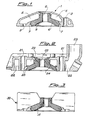
- a four-stroke head is shown. Also here, the insert in copper or copper alloy 40 is connected to the aluminium casting 41 by teeth and interpenetrating faces 42. It should be noted that the hole for the spark plug 43 in the insert and the valve seats 44 are machined directly in the insert itself without recourse to the customery seats in hard materials of the conventional head, indicated by the dotted line 45 in Fig. 4.
- the invention can be applied to engines for agriculture, for example, motor-saws, hedge-trimmers, in general small in size and widely used.
- Such motors must provide a high power/weight ratio while, for reasons of weight and size, the cooling systems are undersized (small ventilators, air passages, etc.).
- the engine is usually air-cooled and the cylinder and head are usually a single casting, as illustrated in Fig. 6.
- the aluminium casting 50 with a copper insert 51 in the head area, to locally reduce the temperature under spark plug, for the same cooling conditions.
- One of the biggest problems with these engines is, in fact, the high temperatures reached near the spark plug.
- said copper or copper allow insert 60 can be mechanically positioned after the casting of aluminium head 62, as shown in figures 7 and 8.
- Said head 62 is machined at the surfaces 64 and 66 and a pre-formed copper insert 60 is mounted by heat shrinkage or with the use of O-rings (68 and 70; fig. 8) in a high temperature rubber material.
- the insert 60 is kept in its operating position by a butting parts lying against the upper surface of cylinder 72 which is connected to the head by bolts 74, as usual.
Landscapes
- Engineering & Computer Science (AREA)
- Chemical & Material Sciences (AREA)
- Combustion & Propulsion (AREA)
- Mechanical Engineering (AREA)
- General Engineering & Computer Science (AREA)
- Cylinder Crankcases Of Internal Combustion Engines (AREA)
Applications Claiming Priority (2)
| Application Number | Priority Date | Filing Date | Title |
|---|---|---|---|
| IT2177885 | 1985-07-31 | ||
| IT21778/85A IT1200699B (it) | 1985-07-31 | 1985-07-31 | Testata per motori alternativi a combustione interna |
Publications (2)
| Publication Number | Publication Date |
|---|---|
| EP0210601A2 true EP0210601A2 (de) | 1987-02-04 |
| EP0210601A3 EP0210601A3 (de) | 1987-08-05 |
Family
ID=11186727
Family Applications (1)
| Application Number | Title | Priority Date | Filing Date |
|---|---|---|---|
| EP86110188A Withdrawn EP0210601A3 (de) | 1985-07-31 | 1986-07-24 | Zylinderkopf für eine Brennkraftmaschine |
Country Status (2)
| Country | Link |
|---|---|
| EP (1) | EP0210601A3 (de) |
| IT (1) | IT1200699B (de) |
Cited By (3)
| Publication number | Priority date | Publication date | Assignee | Title |
|---|---|---|---|---|
| AT404163B (de) * | 1991-12-18 | 1998-09-25 | Avl Verbrennungskraft Messtech | Zylinderkopf für mehrzylindrige brennkraftmaschine |
| DE10133757A1 (de) * | 2001-07-11 | 2003-02-13 | Mahle Ventiltrieb Gmbh | Einsatz als Bodenbereich eines Zylinderkopfes |
| FR2963669A1 (fr) * | 2010-08-06 | 2012-02-10 | Jean Francois Chiandetti | Echangeur thermique interne pour moteur a combustion externe, compresseur isotherme, pompe a chaleur et mecanisme refrigerant place au sein du volume de travail |
Family Cites Families (6)
| Publication number | Priority date | Publication date | Assignee | Title |
|---|---|---|---|---|
| US1693520A (en) * | 1928-01-30 | 1928-11-27 | Kondo Rennosuke | Cylinder of an internal-combustion engine |
| BE405059A (de) * | 1933-09-20 | |||
| GB583806A (en) * | 1943-06-29 | 1946-12-31 | Bristol Aeroplane Co Ltd | Improvements in or relating to cylinder heads for internal combustion engines |
| GB567660A (en) * | 1943-07-12 | 1945-02-26 | Henry Weslake | Improvements in or relating to cylinder heads for internal-combustion engines |
| FR910485A (fr) * | 1944-03-18 | 1946-06-07 | Mecanique Du Ct Atel | Procédé de fabrication de culasse de moteur en alliage léger |
| US2716969A (en) * | 1951-07-25 | 1955-09-06 | Durex S A | Air-or liquid-cooled cylinder head for internal combustion engines |
-
1985
- 1985-07-31 IT IT21778/85A patent/IT1200699B/it active
-
1986
- 1986-07-24 EP EP86110188A patent/EP0210601A3/de not_active Withdrawn
Cited By (3)
| Publication number | Priority date | Publication date | Assignee | Title |
|---|---|---|---|---|
| AT404163B (de) * | 1991-12-18 | 1998-09-25 | Avl Verbrennungskraft Messtech | Zylinderkopf für mehrzylindrige brennkraftmaschine |
| DE10133757A1 (de) * | 2001-07-11 | 2003-02-13 | Mahle Ventiltrieb Gmbh | Einsatz als Bodenbereich eines Zylinderkopfes |
| FR2963669A1 (fr) * | 2010-08-06 | 2012-02-10 | Jean Francois Chiandetti | Echangeur thermique interne pour moteur a combustion externe, compresseur isotherme, pompe a chaleur et mecanisme refrigerant place au sein du volume de travail |
Also Published As
| Publication number | Publication date |
|---|---|
| EP0210601A3 (de) | 1987-08-05 |
| IT8521778A0 (it) | 1985-07-31 |
| IT1200699B (it) | 1989-01-27 |
Similar Documents
| Publication | Publication Date | Title |
|---|---|---|
| US6295963B1 (en) | Four cycle engine for a marine propulsion system | |
| US2456272A (en) | Engine cylinder construction | |
| US4911109A (en) | Cooling system for heat insulating engine | |
| US3521613A (en) | Engine with die-cast static parts | |
| US6321699B1 (en) | Spheroidal rotary valve for combustion engines | |
| JPS59183054A (ja) | 内燃機関用のシリンダユニツト及びその製造方法 | |
| US3081754A (en) | Internal combustion engines, in particular of the constant pressure cycle type | |
| US4541368A (en) | Process and device for the rapid warmup and thermal regulation of the lubricating oil of an internal combustion engine | |
| US4759325A (en) | Rotary engine cooling system | |
| US4522161A (en) | Valve seat inserts | |
| EP0210601A2 (de) | Zylinderkopf für eine Brennkraftmaschine | |
| JPH0226708U (de) | ||
| JPH0613861B2 (ja) | 2サイクルエンジンのピストン | |
| US7389755B2 (en) | Tandem-piston engine | |
| US5755190A (en) | Reciprocating machine with cooling jacket | |
| JP3885260B2 (ja) | エンジンの冷却装置 | |
| GB567660A (en) | Improvements in or relating to cylinder heads for internal-combustion engines | |
| US2401630A (en) | Engine | |
| JPH0426679Y2 (de) | ||
| US5193499A (en) | Cast inter-cylinder cooling passage for internal combustion motors | |
| JP2560425B2 (ja) | 断熱エンジンの構造 | |
| RU2031215C1 (ru) | Комбинированная система охлаждения мотоциклетного двигателя внутреннего сгорания | |
| JPS6128013Y2 (de) | ||
| GB2122722A (en) | Accommodation of expansion within a piston | |
| US2853062A (en) | Engine structure |
Legal Events
| Date | Code | Title | Description |
|---|---|---|---|
| PUAI | Public reference made under article 153(3) epc to a published international application that has entered the european phase |
Free format text: ORIGINAL CODE: 0009012 |
|
| AK | Designated contracting states |
Kind code of ref document: A2 Designated state(s): AT BE CH DE FR GB LI NL SE |
|
| PUAL | Search report despatched |
Free format text: ORIGINAL CODE: 0009013 |
|
| AK | Designated contracting states |
Kind code of ref document: A3 Designated state(s): AT BE CH DE FR GB LI NL SE |
|
| 17P | Request for examination filed |
Effective date: 19880122 |
|
| 17Q | First examination report despatched |
Effective date: 19881208 |
|
| STAA | Information on the status of an ep patent application or granted ep patent |
Free format text: STATUS: THE APPLICATION HAS BEEN WITHDRAWN |
|
| 18W | Application withdrawn |
Withdrawal date: 19890506 |
|
| R18W | Application withdrawn (corrected) |
Effective date: 19890506 |
|
| RIN1 | Information on inventor provided before grant (corrected) |
Inventor name: PANZERI, UMBERTO |