EP0210651B1 - Dispositif pour agiter et similaire - Google Patents
Dispositif pour agiter et similaire Download PDFInfo
- Publication number
- EP0210651B1 EP0210651B1 EP86110478A EP86110478A EP0210651B1 EP 0210651 B1 EP0210651 B1 EP 0210651B1 EP 86110478 A EP86110478 A EP 86110478A EP 86110478 A EP86110478 A EP 86110478A EP 0210651 B1 EP0210651 B1 EP 0210651B1
- Authority
- EP
- European Patent Office
- Prior art keywords
- rotary body
- electro
- tank
- magnetic coil
- treating device
- Prior art date
- Legal status (The legal status is an assumption and is not a legal conclusion. Google has not performed a legal analysis and makes no representation as to the accuracy of the status listed.)
- Expired - Lifetime
Links
- 238000003756 stirring Methods 0.000 claims description 41
- 238000011282 treatment Methods 0.000 claims description 15
- 239000000463 material Substances 0.000 claims description 14
- 239000004020 conductor Substances 0.000 claims description 7
- 239000006185 dispersion Substances 0.000 claims description 4
- 239000002826 coolant Substances 0.000 claims description 3
- 238000002156 mixing Methods 0.000 claims description 3
- 238000004898 kneading Methods 0.000 claims description 2
- 238000001816 cooling Methods 0.000 description 8
- XLYOFNOQVPJJNP-UHFFFAOYSA-N water Substances O XLYOFNOQVPJJNP-UHFFFAOYSA-N 0.000 description 4
- 238000007789 sealing Methods 0.000 description 3
- XEEYBQQBJWHFJM-UHFFFAOYSA-N Iron Chemical compound [Fe] XEEYBQQBJWHFJM-UHFFFAOYSA-N 0.000 description 2
- 229920006362 Teflon® Polymers 0.000 description 2
- 230000001939 inductive effect Effects 0.000 description 2
- 229910000976 Electrical steel Inorganic materials 0.000 description 1
- 238000010276 construction Methods 0.000 description 1
- 230000000694 effects Effects 0.000 description 1
- 230000005674 electromagnetic induction Effects 0.000 description 1
- 229910052742 iron Inorganic materials 0.000 description 1
- 239000005300 metallic glass Substances 0.000 description 1
Images



Classifications
-
- B—PERFORMING OPERATIONS; TRANSPORTING
- B01—PHYSICAL OR CHEMICAL PROCESSES OR APPARATUS IN GENERAL
- B01F—MIXING, e.g. DISSOLVING, EMULSIFYING OR DISPERSING
- B01F33/00—Other mixers; Mixing plants; Combinations of mixers
- B01F33/45—Magnetic mixers; Mixers with magnetically driven stirrers
- B01F33/453—Magnetic mixers; Mixers with magnetically driven stirrers using supported or suspended stirring elements
- B01F33/4534—Magnetic mixers; Mixers with magnetically driven stirrers using supported or suspended stirring elements using a rod for supporting the stirring element, e.g. stirrer sliding on a rod or mounted on a rod sliding in a tube
-
- B—PERFORMING OPERATIONS; TRANSPORTING
- B01—PHYSICAL OR CHEMICAL PROCESSES OR APPARATUS IN GENERAL
- B01F—MIXING, e.g. DISSOLVING, EMULSIFYING OR DISPERSING
- B01F33/00—Other mixers; Mixing plants; Combinations of mixers
- B01F33/45—Magnetic mixers; Mixers with magnetically driven stirrers
- B01F33/453—Magnetic mixers; Mixers with magnetically driven stirrers using supported or suspended stirring elements
Definitions
- the invention relates to a treating device for stirring treatment according to the preamble of claim 1.
- JP-A-60-125240 discloses a stirring device comprising a rotary body located in a treating tank. On this rotary body permanent magnets are provided in opposed relation to permanent magnets which are arranged on a shaft structure rotatably provided in the tank and rotated by a drive apparatus provided outside the tank. In this way the motor must be provided separately from the stirring blades and some problems arise as to sealing the treatment tank.
- a rotary body having a stirring blade is made of conducting material and is rotatably supported within the treating tank. Adjacent the rotary body, an electro-magnetic coil which generates a revolving magnetic field is located, and by the electro magnetic inductive action of the revolving magnetic field, the rotary body is rotated to effect stirring treatment.
- the relation between the rotary body and the electro-magnetic coil includes the case where the rotary body is located to surround the electro-magnetic coil and the case where the electro-magnetic coil is located to surround the rotary body.
- the device according to this invention can be applied to the stirring treatments for mixing, stirring, agitating, kneading, blending, dispersion, medium dispersion and the like.
- stirring treatment as an example, where the material to be treated is received in a stirring tank.
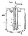
- Fig. 1 is a vertical sectional view of a device according to this invention, wherein a rotary body is located outside of an electro-magnetic coil.
- Fig. 2 is a vertical sectional view of other embodiment of this invention, having a sleeve-shaped rotary body.
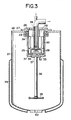
- Fig. 3 is a vertical sectional view of other embodiment of this invention, wherein a stirring blade is hung down.
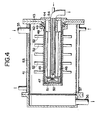
- Fig. 4 is a vertical sectional view of other embodiment of this invention, wherein a stirring tank is laterally set up.
- Fig. 5 is a vertical sectional view of other embodiment, wherein a rotary body is located inside of an electro-magnetic coil.
- Fig. 6 is a vertical sectional view of other embodiment of this invention, wherein a rotary body is located without providing a wall member between the rotary body and the electro-magnetic coil.
- a tank 1 has a canopy plate 2 on its top, in a hole 3 of the plate, a flange 5 of a cover plate 4 is inserted and secured by bolts (not shown), and a bearing 6 is attached to the flange.
- a supporting member 7 is attached to the cover plate 4 by bolts (not shown) to seal the tank.
- the supporting member is provided with a closed cylindrical wall member 8 extending within the tank, and by means of the wall member, an isolated space 9 is formed within the tank. Within the space, an electro-magnetic coil 10 which generates a revolving magnetic field is provided.
- a cooling pipe 11 is provided inside of the coil and the cooling pipe is passed by such a cooling medium as water, air and the like, to absorb the generated heat of the coil.
- the electro-magnetic coil 10 is shown as one set; however, plural sets may be provided if desired.
- a rotary body 12 is provided so as to be driven by an electro-magnetic induction due to the revolving magnetic field.
- the rotary body shown in Fig. 1 is a cylindrical body having a bottom 13 surrounding the outer periphery of the wall member, and it may be an annular body (not shown) loosely put on the wall member.
- the annular body in case of the annular body, it is supported by suitable means at a position corresponding to the outside of the electro-magnetic coil.
- the whole portion of the rotary body or at least a portion corresponding to the electro-magnetic coil is formed of the conducting material such as iron, silicon steel plate, amorphous metal and the like, so as to be rotated by the electro-magnetic inductive action, as mentioned above.
- the rotary body 12 is supported on its upper portion by a sliding bearing of Teflon ®, roller bearing, magnetic bearing and other suitable bearing 6, and an axis 14 provided on the inside of the bottom 13 is supported by a bearing 16 attached to a bottom 15 of the wall member 8.
- a stirring blade 17 is fitted, and the stirring blade may be provided in plural.
- a jacket 18 is provided, in which a temperature controlled medium such as water is circulated to be able to control the temperature of the material to be treated.
- a revolving magnetic field is generated.
- the rotary body 12 will begin to rotate, thus, enabling the stirring treatment.
- the material may be taken out from an exit (not shown).
- two or more rotary bodies may be provided within the tank.
- Fig. 2 shows other embodiment of this invention, quite alike the device of Fig. 1.
- the rotary body 12 is a cylindrical body having a bottom, while in Fig. 2, the rotary body is a sleeve-shaped rotary body 19, whose bearing 20 is a magnetic bearing.
- Others are constructions similar to the device of Fig. 1.
- FIG. 3 shows another embodiment of this invention.
- a tank 21 has a canopy plate 22 on its top and a flange 23 provided on the canopy plate has a bearing 24, on which a flange 26 provided on the upper portion of a rotary body 25 is hung, thereby the rotary body is rotatably fitted.
- a supporting member 27 is attached, and on that member a cylindrical wall member 28 is provided.
- an electro-magnetic coil 30 which generates the revolving magnetic field is provided.
- the rotary body 25 is made of conducting material, and an axis 32 provided on a bottom 31 is supported by a bearing 34 provided on a bottom 33 of the wall member 28.
- an attaching portion 37 for attaching a shaft 36 of a stirring blade 35 is provided on the outside of the bottom 31 of the rotary body.
- a cooling pipe 38 for cooling the electro-magnetic coil and a jacket 39 to be provided on the outer periphery of the tank are provided in the same manner as the device of Fig. 1.
- An exit 40 provided on the bottom of the tank can be opened and closed by a valve (not shown).
- the rotary body 25 is rotated by energizing the electro-magnetic coil 30, thereby the stirring blade 35 is rotated to enable stirring treatment.
- the device may be used by simply changing the stirring blades.
- FIG. 4 An embodiment shown in Fig. 4 is a device for continuous treatment.
- a tank 41 is horizontally disposed and a cover plate 43 and a supporting member 44 are attached to the side of an end plate 42.
- the supporting member 44 is provided with a cylindrical wall member 45 in the horizontal direction, and within the wall member, an electro-magnetic coil 46 which generates a revolving magnetic field.
- a rotary body 47 is located surrounding the outer periphery of the wall member; a flange 48 provided on its one end is supported by a bearing 49 provided on a cover plate 42; an axis 50 provided on the other end is supported by a bearing 51 on the wall member 45. Then the rotary body is rotatably supported.
- the electro-magnetic coil 46 On the periphery of the rotary body 47, plural stirring blades 52 are provided. And, the electro-magnetic coil 46 has a length corresponding to the portion of the rotary body provided with the stirring blades; however, plural electro-magnetic coils may be provided corresponding to the portion of each stirring blade.
- a jacket 53 On the periphery of the tank 41, a jacket 53 is provided and inside of the electro-magnetic coil 46, a cooling pipe 54 is provided for cooling.
- the rotary body and the stirring blades 52 are rotated.
- the material to be treated entered from an inlet 55 is treated by the stirring blades 52 and can be continuously taken out from an exit 56. If a screen 57 is provided within the tank, and the media are put in, the device may also be used as a continuous media dispersion machine and a wet crusher.
- Fig. 5 shows an embodiment of this invention, wherein a rotary body is located inside of an electro-magnetic coil.
- a tank 58 has a canopy plate 59 on its top, and a cover plate 60 is attached onto the canopy plate.
- a supporting member 61 is attached, and an upper portion of a rotary shaft 64 having a stirring blade 62 and a rotary body 63 is rotatably attached to the supporting member.
- the rotary shaft 64 is provided with a flange 65, which is supported by the magnetic bearing 66 in a floating manner, and the bearing portion is covered by a top plate 67.
- a rotary body 63 made of conducting material is provided, and a wall member 69 is provided on the supporting member 61 so as to form a receiving portion 68 around the rotary body.
- an electro-magnetic coil 70 which generates a revolving magnetic field is provided.
- the rotary body and electro-magenetic coil may be provided in plural and in parallel.
- a jacket 71 through which a cooling media such as water, air and the like will pass so as to absorb generated heat of the electro-magnetic coil 70, is provided.
- the jacket may be provided on the receiving portion adjacent the electro-magnetic coil.
- a jacket 72 is provided, in which a temperature controlled media such as water are passed through to control the temperature of the material to be treated.
- the material to be treated by stirring When the material to be treated by stirring is received in a tank through the inlet (not shown) and the electro-magnetic coil 70 is energized, a revolving magnetic field is generated, and by the magnetic field the rotary body 63 is rotated, thereby the stirring blade 62 is rotated to enable the stirring treatment. After treatment, the material may be taken out from the exit (not shown).
- the tank is a vertical type, but it may be a horizontal type, and the material may be continuously treated.
- a wall member is provided between the electro-magnetic coil and a rotary body; however, the wall member may be dispensed with.
- Fig. 6 shows such embodiment of this invention.
- a canopy plate 74 provided on a tank 73 has a cylindrical portion 75 near its center, and in that portion a supporting cylinder 76 is fitted.
- the upper portion of the supporting cylinder is closed by a cover plate 77.
- a rotary body 78 is provided, whose upper part is closed by the cover plate, and a flange 79 formed on the upper edge and a middle portion of the rotary body are supported by a sliding bearing of Teflon ®, roller bearing, magnetic bearing, and other suitable bearings 80, 81.
- an electro-magnetic coil 83 which generates the revolving magnetic field adjacent a cylindrical wall 82, is located and in the drawing, a set of the electro-magnetic coil is attached to a supporting rod 84, but in case of need, plural sets may be provided.
- a cooling pipe 85 is provided inside of the coil to circulate the cooling medium so as to absorb the generated heat of the coil.
- the whole portion of the rotary body or at least a portion corresponding to the electro-magnetic coil is formed of suitable conducting material similar to the above mentioned embodiment.
- the rotary body may be directly connected with the stirring blade, but in the drawing, a shaft 86 is fitted to the lower part, and on that shaft, a stirring blade 87 is provided. Further, plural numbers of stirring blade shafts and of rotary body shafts may be provided.
- a jacket 88 is provided on the outside of the tank 73.
- the material to be treated is received within the tank from an inlet (not shown) provided in the suitable position of the tank, then the electro-magnetic coil 83 is energized, so that the revolving magnetic field is generated, the rotary body 78 will rotate and the stirring blade 87 is rotated, enabling the stirring treatment. And, the outlet 89 is closed by a valve (not shown).
- this invention is formed as mentioned above and the rotary body for stirring treatment of the material to be treated is driven by the revolving magnetic field, usual mechanical loss are never caused, and also problems of the shaft sealing do not arise. Therefore the inventive device may be suitably used for sealable treating tank, reaction tank, etc.
Landscapes
- Chemical & Material Sciences (AREA)
- Chemical Kinetics & Catalysis (AREA)
- Mixers With Rotating Receptacles And Mixers With Vibration Mechanisms (AREA)
- Mixers Of The Rotary Stirring Type (AREA)
Claims (9)
- Dispositif de traitement pour les opérations d'agitation, de mélange, de malaxage, de dispersion de matière à traiter qui sont introduites dans un réservoir de traitement (1), comprenant
une pale d'agitation (17) montée sur un corps rotatif (12) lequel corps rotatif (12) est monté de façon rotative dans le réservoir de traitement (1) et mis en rotation par un champ magnétique tournant,
caractérisé en ce qu'une bobine éléctromagnétique (10) est située à l'intérieur du réservoir (1) pour produire le champ magnétique tournant et
en ce que le corps rotatif (12) est réalisé en matière conductrice ou comprend une matière conductrice de sorte que le corps rotatif (12) est mis en rotation directement par le champ magnétique tournant émis par la bobine électromagnétique (10). - Dispositif de traitement selon la revendication 1, dans lequel le corps rotatif (12 ; 19 ; 25 ; 47 ; 78) entoure une périphérie extérieure de la bobine électromagnétique (10 ; 30 ; 46 ; 83).
- Dispositif de traitement selon la revendication 1, dans lequel le corps rotatif (63) est entouré de la bobine électromagnétique (70).
- Dispositif de traitement selon la revendication 1, dans lequel le corps rotatif (12 ; 19 ; 25 ; 47 ; 63 ; 78) est cylindrique.
- Dispositif de traitement selon la revendication 1, dans lequel le corps rotatif est annulaire.
- Dispositif de traitement selon la revendication 1, dans lequel la bobine électromagnétique (10 ; 30 ; 46) est prévue à l'intérieur d'un élément de paroi cylindrique (8 ; 28 ; 45) à l'extérieur duquel est situé le corps rotatif (12 ; 13 ; 25 ; 47).
- Dispositif de traitement selon la revendication 1, dans lequel la bobine électromagnétique (70) est disposée à l'intérieur d'une portion de réception formée par un élément de paroi (69) et s'étendant autour du corps rotatif (63).
- Dispositif de traitement selon la revendication 1, dans lequel les axes longitudinaux du réservoir de traitement (41) et du corps rotatif (47) sont horizontaux.
- Dispositif de traitement selon la revendication 1, dans lequel la chaleur produite par la bobine électromagnétique (10) est absorbée par un agent de refroidissement passant à l'intérieur de la bobine (10) et la température de la matière de traitement à l'intérieur du réservoir (1 ; 21 ; 41 ; 58 ; 73) est régulée par un agent à température régulée acheminé à l'extérieur du réservoir (1).
Applications Claiming Priority (6)
| Application Number | Priority Date | Filing Date | Title |
|---|---|---|---|
| JP60169732A JPS6230538A (ja) | 1985-08-02 | 1985-08-02 | 撹拌等の処理装置 |
| JP169732/85 | 1985-08-02 | ||
| JP169731/85 | 1985-08-02 | ||
| JP60169731A JPS6230537A (ja) | 1985-08-02 | 1985-08-02 | 撹拌等の処理装置 |
| JP239602/85 | 1985-10-28 | ||
| JP60239602A JPS62102824A (ja) | 1985-10-28 | 1985-10-28 | 撹拌等の処理装置 |
Publications (3)
| Publication Number | Publication Date |
|---|---|
| EP0210651A2 EP0210651A2 (fr) | 1987-02-04 |
| EP0210651A3 EP0210651A3 (en) | 1988-09-21 |
| EP0210651B1 true EP0210651B1 (fr) | 1991-10-09 |
Family
ID=27323224
Family Applications (1)
| Application Number | Title | Priority Date | Filing Date |
|---|---|---|---|
| EP86110478A Expired - Lifetime EP0210651B1 (fr) | 1985-08-02 | 1986-07-29 | Dispositif pour agiter et similaire |
Country Status (2)
| Country | Link |
|---|---|
| EP (1) | EP0210651B1 (fr) |
| DE (1) | DE3681846D1 (fr) |
Cited By (1)
| Publication number | Priority date | Publication date | Assignee | Title |
|---|---|---|---|---|
| CN103008603A (zh) * | 2011-09-27 | 2013-04-03 | 苏州三基铸造装备股份有限公司 | 金属合金半固态浆料的制备方法及装置 |
Families Citing this family (16)
| Publication number | Priority date | Publication date | Assignee | Title |
|---|---|---|---|---|
| FI90732C (fi) * | 1989-05-09 | 1994-03-25 | Ahlstroem Oy | Sekoitin |
| DE3942679A1 (de) * | 1989-12-22 | 1991-06-27 | Ekato Ind Anlagen Verwalt | Mischvorrichtung |
| CN1017692B (zh) * | 1990-02-26 | 1992-08-05 | 华南理工大学 | 电磁动态塑化挤出方法及设备 |
| DE4101695A1 (de) * | 1991-01-22 | 1992-08-13 | Agfa Gevaert Ag | Abdeck- und reinigungsvorrichtung fuer einen tintenspritzkopf |
| GB2269115B (en) * | 1992-07-29 | 1996-03-06 | Weaverbrook Ltd | Fluid treatment apparatus |
| DE4232935C2 (de) * | 1992-10-01 | 1996-03-28 | Mavag Verfahrenstech Ag | Magnetrührwerk |
| US5533803A (en) * | 1992-10-01 | 1996-07-09 | Mavag Verfahrenstechnik Ag | Magnetic stirring apparatus with contactless coupling between stirring shaft and stirring tool |
| DE29608616U1 (de) * | 1996-05-11 | 1996-08-01 | SBF Wasser und Umwelt Zweigniederlassung der Preussag Anlagenbau GmbH, 31228 Peine | Mischgefäß |
| US7396153B2 (en) * | 2005-04-05 | 2008-07-08 | Andersson Per-Olof K | Ultraclean magnetic mixer |
| US7832922B2 (en) | 2007-11-30 | 2010-11-16 | Levitronix Gmbh | Mixing apparatus and container for such |
| DE102008025507A1 (de) | 2008-05-28 | 2009-12-03 | Sartorius Stedim Biotech Gmbh | Mischsystem |
| DE102009021992B3 (de) * | 2009-05-19 | 2010-12-09 | PRG Präzisions-Rührer GmbH | Magnetrührwerk |
| DE102010016014A1 (de) | 2010-03-18 | 2011-09-22 | PRG Präzisions-Rührer GmbH | Antriebseinheit für ein Rührwerk |
| EP3003545A4 (fr) * | 2013-05-28 | 2017-05-17 | Dako Denmark A/S | Procédé et appareil de mélange d'un réactif |
| DE102015106566B3 (de) * | 2015-04-28 | 2016-06-09 | PRG Präzisions-Rührer GmbH | Antriebseinheit für ein Rührwerk und Rührwerk |
| CN116218641A (zh) * | 2023-03-03 | 2023-06-06 | 百仑生物科技(江苏)有限公司 | 一种洁净型生物反应器 |
Family Cites Families (2)
| Publication number | Priority date | Publication date | Assignee | Title |
|---|---|---|---|---|
| DE3200165A1 (de) * | 1982-01-07 | 1983-07-14 | Goavec S.A., 61006 Alençon, Orne | Ruehrwerk |
| JPS6291692A (ja) * | 1985-10-16 | 1987-04-27 | Ngk Insulators Ltd | 回転機器用マグネツト駆動装置 |
-
1986
- 1986-07-29 EP EP86110478A patent/EP0210651B1/fr not_active Expired - Lifetime
- 1986-07-29 DE DE8686110478T patent/DE3681846D1/de not_active Expired - Fee Related
Cited By (1)
| Publication number | Priority date | Publication date | Assignee | Title |
|---|---|---|---|---|
| CN103008603A (zh) * | 2011-09-27 | 2013-04-03 | 苏州三基铸造装备股份有限公司 | 金属合金半固态浆料的制备方法及装置 |
Also Published As
| Publication number | Publication date |
|---|---|
| EP0210651A3 (en) | 1988-09-21 |
| DE3681846D1 (de) | 1991-11-14 |
| EP0210651A2 (fr) | 1987-02-04 |
Similar Documents
| Publication | Publication Date | Title |
|---|---|---|
| EP0210651B1 (fr) | Dispositif pour agiter et similaire | |
| EP0423925B1 (fr) | Agitateur magnétique | |
| JP4245673B2 (ja) | 攪拌装置付きアルミ溶解炉、溶融アルミ攪拌装置及び溶湯アルミ攪拌方法 | |
| JP4013211B2 (ja) | 媒体分散装置 | |
| EP0249879B1 (fr) | Appareil de dispersion et de broyage | |
| US5497948A (en) | Basket media mill with extended impeller | |
| EP0322623A2 (fr) | Appareil de dispersion et de broyage | |
| EP0526699A1 (fr) | Appareil de broyage et de dispersion | |
| DE69410838T2 (de) | Autoklav | |
| US4729664A (en) | In-line mixer | |
| US4637555A (en) | Circulation type homogenizing apparatus | |
| EP0774293B1 (fr) | Dispositif de refroidissement | |
| JPH0724439U (ja) | 粉砕機の構造 | |
| US6565024B2 (en) | Dispersing device | |
| JP3238400B2 (ja) | 繊維懸濁液用叩解装置 | |
| US4754437A (en) | Method of making or drying particulate material | |
| JP2004305981A (ja) | ナノレベルの超微粒子を製造するための水冷式遊星運動型ボールミル粉砕機およびその温度制御方法 | |
| JPS62102824A (ja) | 撹拌等の処理装置 | |
| JPH0141089B2 (fr) | ||
| JPS6230538A (ja) | 撹拌等の処理装置 | |
| JPH0463626B2 (fr) | ||
| JP2002079290A (ja) | 水中曝気装置 | |
| CH322234A (de) | Geschlossener Behälter mit hochtourigem Rührwerk | |
| CA1193638A (fr) | Four a induction | |
| JPH0545393Y2 (fr) |
Legal Events
| Date | Code | Title | Description |
|---|---|---|---|
| PUAI | Public reference made under article 153(3) epc to a published international application that has entered the european phase |
Free format text: ORIGINAL CODE: 0009012 |
|
| AK | Designated contracting states |
Kind code of ref document: A2 Designated state(s): DE FR GB IT |
|
| 17P | Request for examination filed |
Effective date: 19870629 |
|
| PUAL | Search report despatched |
Free format text: ORIGINAL CODE: 0009013 |
|
| AK | Designated contracting states |
Kind code of ref document: A3 Designated state(s): DE FR GB IT |
|
| 17Q | First examination report despatched |
Effective date: 19900620 |
|
| GRAA | (expected) grant |
Free format text: ORIGINAL CODE: 0009210 |
|
| AK | Designated contracting states |
Kind code of ref document: B1 Designated state(s): DE FR GB IT |
|
| ITF | It: translation for a ep patent filed | ||
| REF | Corresponds to: |
Ref document number: 3681846 Country of ref document: DE Date of ref document: 19911114 |
|
| ET | Fr: translation filed | ||
| PLBE | No opposition filed within time limit |
Free format text: ORIGINAL CODE: 0009261 |
|
| STAA | Information on the status of an ep patent application or granted ep patent |
Free format text: STATUS: NO OPPOSITION FILED WITHIN TIME LIMIT |
|
| 26N | No opposition filed | ||
| PGFP | Annual fee paid to national office [announced via postgrant information from national office to epo] |
Ref country code: FR Payment date: 19930528 Year of fee payment: 8 |
|
| PGFP | Annual fee paid to national office [announced via postgrant information from national office to epo] |
Ref country code: GB Payment date: 19930723 Year of fee payment: 8 |
|
| PGFP | Annual fee paid to national office [announced via postgrant information from national office to epo] |
Ref country code: DE Payment date: 19930819 Year of fee payment: 8 |
|
| PG25 | Lapsed in a contracting state [announced via postgrant information from national office to epo] |
Ref country code: GB Effective date: 19940729 |
|
| GBPC | Gb: european patent ceased through non-payment of renewal fee |
Effective date: 19940729 |
|
| PG25 | Lapsed in a contracting state [announced via postgrant information from national office to epo] |
Ref country code: FR Effective date: 19950331 |
|
| PG25 | Lapsed in a contracting state [announced via postgrant information from national office to epo] |
Ref country code: DE Effective date: 19950401 |
|
| REG | Reference to a national code |
Ref country code: FR Ref legal event code: ST |
|
| PG25 | Lapsed in a contracting state [announced via postgrant information from national office to epo] |
Ref country code: IT Free format text: LAPSE BECAUSE OF NON-PAYMENT OF DUE FEES;WARNING: LAPSES OF ITALIAN PATENTS WITH EFFECTIVE DATE BEFORE 2007 MAY HAVE OCCURRED AT ANY TIME BEFORE 2007. THE CORRECT EFFECTIVE DATE MAY BE DIFFERENT FROM THE ONE RECORDED. Effective date: 20050729 |