EP0210688A2 - Signalsendeanlage und in der Anlage verwendeter Sender und Empfänger - Google Patents
Signalsendeanlage und in der Anlage verwendeter Sender und Empfänger Download PDFInfo
- Publication number
- EP0210688A2 EP0210688A2 EP86201177A EP86201177A EP0210688A2 EP 0210688 A2 EP0210688 A2 EP 0210688A2 EP 86201177 A EP86201177 A EP 86201177A EP 86201177 A EP86201177 A EP 86201177A EP 0210688 A2 EP0210688 A2 EP 0210688A2
- Authority
- EP
- European Patent Office
- Prior art keywords
- channels
- sub
- signals
- frequency
- frequency bands
- Prior art date
- Legal status (The legal status is an assumption and is not a legal conclusion. Google has not performed a legal analysis and makes no representation as to the accuracy of the status listed.)
- Granted
Links
Images

Classifications
-
- H—ELECTRICITY
- H04—ELECTRIC COMMUNICATION TECHNIQUE
- H04B—TRANSMISSION
- H04B7/00—Radio transmission systems, i.e. using radiation field
- H04B7/02—Diversity systems; Multi-antenna system, i.e. transmission or reception using multiple antennas
- H04B7/12—Frequency diversity
-
- H—ELECTRICITY
- H03—ELECTRONIC CIRCUITRY
- H03C—MODULATION
- H03C1/00—Amplitude modulation
-
- H—ELECTRICITY
- H03—ELECTRONIC CIRCUITRY
- H03D—DEMODULATION OR TRANSFERENCE OF MODULATION FROM ONE CARRIER TO ANOTHER
- H03D1/00—Demodulation of amplitude-modulated oscillations
-
- H—ELECTRICITY
- H04—ELECTRIC COMMUNICATION TECHNIQUE
- H04B—TRANSMISSION
- H04B1/00—Details of transmission systems, not covered by a single one of groups H04B3/00 - H04B13/00; Details of transmission systems not characterised by the medium used for transmission
- H04B1/68—Details of transmission systems, not covered by a single one of groups H04B3/00 - H04B13/00; Details of transmission systems not characterised by the medium used for transmission for wholly or partially suppressing the carrier or one side band
-
- H—ELECTRICITY
- H04—ELECTRIC COMMUNICATION TECHNIQUE
- H04L—TRANSMISSION OF DIGITAL INFORMATION, e.g. TELEGRAPHIC COMMUNICATION
- H04L5/00—Arrangements affording multiple use of the transmission path
- H04L5/22—Arrangements affording multiple use of the transmission path using time-division multiplexing
- H04L5/26—Arrangements affording multiple use of the transmission path using time-division multiplexing combined with the use of different frequencies
Definitions
- the present invention relates to a signal transmission system, for example a radio system, which has particular application for use with direct conversion receivers.
- Direct conversion receivers have a number of advantages in that they are a means of avoiding having to provide an anti-image front-end filter and a crystal i.f. filter and in that they can be implemented as an integrated radio receiver.
- a direct conversion receiver comprises a pair of front-end mixers which produce quadrature related outputs. These outputs are low passed filtered and after one output has been phase shifted by a further 90 degrees then both are applied to a demodulator.
- the signals emerging from the front end mixers are folded around zero frequency, that is d.c., and the d.c. offset, which is inevitably present, appears in the middle of the signal spectrum. This d.c. offset if amplified would cause the amplifier to operate on one side of its characteristic.
- d.c. block capacitors A disadvantage of the use of d.c. block capacitors is that in eliminating the d.c. and low frequency components of the signals from the mixers then a notch or hole appears in the middle of the transmitted signal spectrum.
- Present modulation schemes can tolerate this hole in the middle of the spectrum but it is possible that a modulation scheme might be devised which because of the presence of a hole cannot be implemented using a direct conversion receiver.
- One method of mitigating the notch-in-the-middle problem is to make the notch as narrow as possible by using high capacitance value capacitors but these have the disadvantages of being physically large and lengthening the time constant of the circuit and its settling time at switch-on.
- An object of the present invention is to avoid the problems caused by a notch being present in the middle of a modulating signal when it is received by direct conversion receiver, and to allow rapid settling of the receiver on switch-on.
- a signal transmission system comprising at least two signal channels, each signal channel being split into two sub-channels occupying mutually different frequency bands for transmission, the frequency bands occupied by the sub-channels of one channel being interleaved with the frequency bands occupied by the sub-channels of at least one other channel so that the frequency band occupied by at least one sub-channel of one channel is disposed between the frequency bands occupied by the sub-channels of another channel.
- the local oscillator can be tuned to the mid-point between the frequency bands occupied by the two sub-channels corresponding to a selected channel so that unwanted signals together with the d.c. offset can be removed by bandpass filtering.
- the d.c. itself can be removed by a small value capacitor. Consequently the receiver can settle very quickly which means that it can be used in applications such as cordless telephones.
- the transmission system may be allocated a dedicated block of adjacent frequency bands.
- the transmission spectrum may comprise a first sequence of frequency bands occupied by first sub-channels of the respective channels arranged in a predetermined order and a second sequence of frequency bands occupied by second sub-channels of the respective channels immediately following the first sequence and arranged in the same predetermined order.
- the channels may be arranged in at least two groups of two or more channels and the transmission spectrum of each group may comprise a first sequence of frequency bands occupied by first sub-channels of the respective channels in the corresponding group arranged in a predetermined order and a second sequence of frequency bands occupied by second sub-channels of these channels immediately following the first sequence and arranged in the same predetermined order.
- a transmitter for use in a radio system in accordance with the present invention comprising means for dividing of an input signal into first and second complementary signals, means for transmitting said complementary signals in first and second sub-channels, respectively, which sub-channels occupy mutually different frequency bands which are situated symmetrically with respect to the transmitter carrier frequency.
- the transmitting means may comprise means for modulating said complementary signals onto first and second sub-carriers the frequency of each of which is equal to half the sub-channel separation frequency, means for obtaining the sum of and the difference between the outputs of the modulating means, means for producing a relative 90 degree phase-shift between the resulting sum and difference signals, means for frequency translating-up the relatively phase-shifted signals using quadrature related carrier signals, and means for combining the frequency translated signals.
- a direct conversion receiver for use in a radio system in accordance with the present invention, the receiver comprising a pair of mixers for producing quadrature related output signals, a local oscillator for supplying to said mixers a signal having a frequency mid-way between the frequency bands occupied by the sub-channels of a selected channel, bandpass filtering means and phase-shifting means for filtering the output signals from the mixers to obtain signals lying within said frequency bands frequency-translated by said mixers and producing a relative 90 degree phase-shift between the output signals of said mixers, summing and differencing means for obtaining the sum of and the difference betwen the filtered and relatively phase-shifted signals, respective demodulating means for the resulting sum and difference signals, and means for combining the output signals of said demodulating means to reconstitute the signals originally supplied to the selected channel.
- a further advantage of the present invention is that it may not be necessary to accurately match the two front end mixers and the associated signal paths in a direct conversion implementation of the receiver in such a system, as the matching is only needed to separate the two wanted sub-channels from each other, and because these are likely to be of similar amplitude (coming from the same transmitter) a matching accuracy equivalent to 30 dB rejection may suffice.
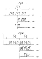
- diagram 1(i) shows the transmitter output spectrum comprising the frequency modulated signal B centred on a carrier signal f c .
- Diagram 1(ii) shows a typical transmission spectrum with adjacent channel signals A and C on either side of the signal B.
- the signal B is mixed down to baseband to produce an i.f. spectrum, diagram 1(iii),in which the signal B is folded about zero and the adjacent channel signals A, C overlap each other.
- the offset produces a filtered signal spectrum of the signal B as shown in diagram 1(iv) in which the adjacent channel signals A, C have been eliminated and a notch 10 is produced at the low frequency end of the spectrum of the signal B.
- the signal B is demodulated using for example a phasing method known per se.
- the notch 10 can be reduced using a high valued d.c. block capacitance this has the disadvantages of being physically large and causing the receiver circuit to have a long time constant which means it requires an undesirably long time to settle at switch-on.
- a transmission system in accordance with the present invention.
- a system operator requires a dedicated block of transmission frequency bands.
- Each signal channel is split into two complementary sub-channels, b , b' diagram 2(i), occupying mutually different and separated frequency bands for transmission using a carrier frequency f c .
- the frequency bands occupied by the sub-channels of one channel are interleaved with the frequency bands occupied by the sub-channels of another channel or other channels so that one has a transmission spectrum of a type shown in diagram 2(ii) in which a , a' and c , c' are the frequency bands occupied by the sub-channels of unwanted adjacent channels.
- the required signals are mixed down to baseband by making the local oscillator frequency equal to the mid-point between its two sub-channels, in this example the carrier frequency f c , with the result that the negative frequency sub-channels a , b and c are folded about zero.
- the sub-channels c , a' ; b , b' and a , c' overlap each other, diagram 2(iii).
- the wanted sub-channels b , b' are obtained and subsequently demodulated by the phasing method and combined to form the signal b + b' .
- the wanted signal is spaced from d.c. then it is immaterial if a notch is large or small and consequently a small valued d.c. block capacitor can be used without affecting unduly the settling time at switch-on.
- the arrangement of the frequency bands occupied by the sub-channels and their interleaving may be chosen as desired within the requirement that the frequency band occupied by at least one "unwanted" sub-channel lies between the frequency bands occupied by the "wanted" sub-channels.
- Figure 2 an arrangement is shown in which the bands occupied by the sub-channels are arranged in two groups, one group containing the bands occupied by one sub-channel of each channel arranged in a predetermined sequence and the other group containing the bands occupied by the other sub-channels in the same sequence.
- the transmission spectrum is a , b , c , a' , b' , c' .
- the two group arrangement can be used but as an alternative pairs of groups concatenated with other pairs of groups can be formed.
- the bands occupied by their respective pairs of sub-channels can be arranged in the spectrum as follows a , b , c , a' , b' , c' ; d , e , f , d' , e' , f' ; g , h . i , g' , h' , i' .
- Figure 3 illustrates a transmitter architecture suitable for use in a transmission system in accordance with the present invention.
- a message signal which is to be transmitted is applied to a terminal 12.
- modulators 16 and 18 may be, for example, amplitude or frequency modulators; they are preferably single-sideband modulators.
- the input signal spectrum could for example be split by filters into two frequency bands in the multiplexer 14 which can then be separately translated up to the sub-channel centre frequency to give the sub-channels b and b' .
- the modulator outputs are combined arithmetically in a summing amplifier 20 and a differencing amplifier 22.
- the output of the amplifier 20 is applied to a mixer 26 and the output of the amplifier 22 is phase shifted by 90 degrees in a phase shifter 24 and then applied to a mixer 28.
- These outputs are frequency translated up to the carrier centre-frequency f c by means of a local oscillator 30 whose output is applied directly to the mixer 26 and also is phase shifted by 90 degrees in a phase shifter 32 and applied to the mixer 28.
- the quadrature related outputs of the mixers 26, 28 are combined in a summing amplifier 34 and applied to an antenna 36.
- the transmitter output is shown inset.
- FIG. 4 illustrates a receiver architecture suitable for use in a radio system in accordance with the present invention.
- An antenna 40 is connected to mixers 42, 44.
- a local oscillator 46 whose output frequency is set to the mid-point between the two wanted sub-channels b, b' is connected to the mixer 42 and via a 90 degrees phase shifter 48 to the mixer 44.
- the quadrature related frequency down-converted outputs of the mixers 42, 44 are applied, via gain stages 50, 52 including d.c. block capacitors (not shown), to bandpass filters 54, 56.
- the passbands of the filters 54, 56 are set to pass only the wanted sub-channels b, b'.
- the filtered output from the filter 56 is phase shifted by 90 degrees in a phase shifter 58 and the outputs from which and the filter 54 are arithmetically combined in a differencing amplifier 60 and a summing amplifier 62 to obtain the modulated sub-channels b and b'.
- the outputs' of the amplifiers 60, 62 are applied to demodulators 64, 66 which perform the converse operations to those performed by the modulators 16, 18 to obtain the signals carried in the sub-channels b, b'.
- demultiplexer 68 which performs the converse operation to that performed by the multiplexer 14 to produce the complete message signal at terminal 70.
Landscapes
- Engineering & Computer Science (AREA)
- Signal Processing (AREA)
- Computer Networks & Wireless Communication (AREA)
- Power Engineering (AREA)
- Digital Transmission Methods That Use Modulated Carrier Waves (AREA)
- Transmitters (AREA)
Applications Claiming Priority (2)
| Application Number | Priority Date | Filing Date | Title |
|---|---|---|---|
| GB08517230A GB2177876A (en) | 1985-07-08 | 1985-07-08 | Radio system and a transmitter and a receiver for use in the system |
| GB8517230 | 1985-07-08 |
Publications (3)
| Publication Number | Publication Date |
|---|---|
| EP0210688A2 true EP0210688A2 (de) | 1987-02-04 |
| EP0210688A3 EP0210688A3 (en) | 1988-12-21 |
| EP0210688B1 EP0210688B1 (de) | 1992-01-15 |
Family
ID=10581962
Family Applications (1)
| Application Number | Title | Priority Date | Filing Date |
|---|---|---|---|
| EP19860201177 Expired EP0210688B1 (de) | 1985-07-08 | 1986-07-04 | Signalsendeanlage und in der Anlage verwendeter Sender und Empfänger |
Country Status (7)
| Country | Link |
|---|---|
| US (1) | US4768187A (de) |
| EP (1) | EP0210688B1 (de) |
| JP (1) | JP2594547B2 (de) |
| AU (1) | AU586769B2 (de) |
| DE (1) | DE3683420D1 (de) |
| DK (1) | DK319186A (de) |
| GB (1) | GB2177876A (de) |
Families Citing this family (72)
| Publication number | Priority date | Publication date | Assignee | Title |
|---|---|---|---|---|
| GB2177875A (en) * | 1985-07-08 | 1987-01-28 | Philips Electronic Associated | Radio transmission system |
| US4884265A (en) * | 1987-04-30 | 1989-11-28 | Loral Corporation | Digital demodulator for frequency-division-multiplexed signals |
| US5058107A (en) * | 1989-01-05 | 1991-10-15 | Hughes Aircraft Company | Efficient digital frequency division multiplexed signal receiver |
| US5251218A (en) * | 1989-01-05 | 1993-10-05 | Hughes Aircraft Company | Efficient digital frequency division multiplexed signal receiver |
| AU8185591A (en) * | 1990-06-12 | 1992-01-07 | Motorola, Inc. | Quadrature amplitude modulation synchronization method |
| US5343499A (en) * | 1990-06-12 | 1994-08-30 | Motorola, Inc. | Quadrature amplitude modulation synchronization method |
| AU652371B2 (en) * | 1990-06-29 | 1994-08-25 | Fujitsu Limited | Data transfer system |
| GB9017418D0 (en) * | 1990-08-08 | 1990-09-19 | Gen Electric Co Plc | Half frequency mixer |
| US5208804A (en) * | 1990-10-30 | 1993-05-04 | Motorola, Inc. | Flexible-bandwidth radio |
| US5170413A (en) * | 1990-12-24 | 1992-12-08 | Motorola, Inc. | Control strategy for reuse system assignments and handoff |
| GB2258963B (en) * | 1991-08-23 | 1995-06-14 | Sony Broadcast & Communication | Sub band filters |
| US5283789A (en) * | 1992-05-15 | 1994-02-01 | Private Satellite Network, Inc. | Communication system providing data and television signals to PC work stations |
| FR2692090B1 (fr) * | 1992-06-04 | 1994-07-22 | Cit Alcatel | Procede d'allocation de frequences porteuses pour la transmission simultanee, notamment sur une liaison optique, d'une pluralite de signaux modules. |
| DE69327837T2 (de) * | 1992-12-01 | 2000-10-12 | Koninklijke Philips Electronics N.V., Eindhoven | Teilband-Diversityübertragungssystem |
| US5794221A (en) | 1995-07-07 | 1998-08-11 | Egendorf; Andrew | Internet billing method |
| US5970410A (en) * | 1996-02-27 | 1999-10-19 | Airnet Communications Corp. | Cellular system plan using in band-translators to enable efficient deployment of high capacity base transceiver systems |
| US5734676A (en) * | 1996-05-24 | 1998-03-31 | International Business Machines Corporation | Apparatus, method and article of manufacture for carrier frequency compensation in a FM radio receiver |
| WO1999004521A2 (en) * | 1997-07-15 | 1999-01-28 | Comsat Corporation | A method and apparatus for segmentation and reassembly of packets/cells over satellite/wireless networks |
| US6091940A (en) | 1998-10-21 | 2000-07-18 | Parkervision, Inc. | Method and system for frequency up-conversion |
| US6061551A (en) | 1998-10-21 | 2000-05-09 | Parkervision, Inc. | Method and system for down-converting electromagnetic signals |
| US6694128B1 (en) | 1998-08-18 | 2004-02-17 | Parkervision, Inc. | Frequency synthesizer using universal frequency translation technology |
| US7515896B1 (en) * | 1998-10-21 | 2009-04-07 | Parkervision, Inc. | Method and system for down-converting an electromagnetic signal, and transforms for same, and aperture relationships |
| US7027786B1 (en) | 1998-10-21 | 2006-04-11 | Parkervision, Inc. | Carrier and clock recovery using universal frequency translation |
| US7236754B2 (en) | 1999-08-23 | 2007-06-26 | Parkervision, Inc. | Method and system for frequency up-conversion |
| US6049706A (en) | 1998-10-21 | 2000-04-11 | Parkervision, Inc. | Integrated frequency translation and selectivity |
| US7039372B1 (en) | 1998-10-21 | 2006-05-02 | Parkervision, Inc. | Method and system for frequency up-conversion with modulation embodiments |
| US6542722B1 (en) | 1998-10-21 | 2003-04-01 | Parkervision, Inc. | Method and system for frequency up-conversion with variety of transmitter configurations |
| US7295826B1 (en) | 1998-10-21 | 2007-11-13 | Parkervision, Inc. | Integrated frequency translation and selectivity with gain control functionality, and applications thereof |
| US6370371B1 (en) | 1998-10-21 | 2002-04-09 | Parkervision, Inc. | Applications of universal frequency translation |
| US6061555A (en) | 1998-10-21 | 2000-05-09 | Parkervision, Inc. | Method and system for ensuring reception of a communications signal |
| US6560301B1 (en) | 1998-10-21 | 2003-05-06 | Parkervision, Inc. | Integrated frequency translation and selectivity with a variety of filter embodiments |
| US6813485B2 (en) | 1998-10-21 | 2004-11-02 | Parkervision, Inc. | Method and system for down-converting and up-converting an electromagnetic signal, and transforms for same |
| FI112741B (fi) | 1998-11-26 | 2003-12-31 | Nokia Corp | Menetelmä ja järjestely RF-signaalien lähettämiseksi ja vastaanottamiseksi tiedonsiirtojärjestelmien erilaisissa radiorajapinnoissa |
| US7006805B1 (en) | 1999-01-22 | 2006-02-28 | Parker Vision, Inc. | Aliasing communication system with multi-mode and multi-band functionality and embodiments thereof, such as the family radio service |
| US6704549B1 (en) | 1999-03-03 | 2004-03-09 | Parkvision, Inc. | Multi-mode, multi-band communication system |
| US6704558B1 (en) | 1999-01-22 | 2004-03-09 | Parkervision, Inc. | Image-reject down-converter and embodiments thereof, such as the family radio service |
| US6853690B1 (en) | 1999-04-16 | 2005-02-08 | Parkervision, Inc. | Method, system and apparatus for balanced frequency up-conversion of a baseband signal and 4-phase receiver and transceiver embodiments |
| US6879817B1 (en) | 1999-04-16 | 2005-04-12 | Parkervision, Inc. | DC offset, re-radiation, and I/Q solutions using universal frequency translation technology |
| US6873836B1 (en) | 1999-03-03 | 2005-03-29 | Parkervision, Inc. | Universal platform module and methods and apparatuses relating thereto enabled by universal frequency translation technology |
| US7110435B1 (en) | 1999-03-15 | 2006-09-19 | Parkervision, Inc. | Spread spectrum applications of universal frequency translation |
| US7110444B1 (en) | 1999-08-04 | 2006-09-19 | Parkervision, Inc. | Wireless local area network (WLAN) using universal frequency translation technology including multi-phase embodiments and circuit implementations |
| US7065162B1 (en) | 1999-04-16 | 2006-06-20 | Parkervision, Inc. | Method and system for down-converting an electromagnetic signal, and transforms for same |
| US7693230B2 (en) | 1999-04-16 | 2010-04-06 | Parkervision, Inc. | Apparatus and method of differential IQ frequency up-conversion |
| US8295406B1 (en) | 1999-08-04 | 2012-10-23 | Parkervision, Inc. | Universal platform module for a plurality of communication protocols |
| US7054296B1 (en) | 1999-08-04 | 2006-05-30 | Parkervision, Inc. | Wireless local area network (WLAN) technology and applications including techniques of universal frequency translation |
| US7072390B1 (en) | 1999-08-04 | 2006-07-04 | Parkervision, Inc. | Wireless local area network (WLAN) using universal frequency translation technology including multi-phase embodiments |
| GB2354411B (en) * | 1999-09-16 | 2003-11-26 | Intek Global Technologies Ltd | Digital data communication |
| US7933555B2 (en) * | 1999-10-21 | 2011-04-26 | Broadcom Corporation | System and method for reducing phase noise |
| US8014724B2 (en) | 1999-10-21 | 2011-09-06 | Broadcom Corporation | System and method for signal limiting |
| US7082171B1 (en) | 1999-11-24 | 2006-07-25 | Parkervision, Inc. | Phase shifting applications of universal frequency translation |
| US6963734B2 (en) | 1999-12-22 | 2005-11-08 | Parkervision, Inc. | Differential frequency down-conversion using techniques of universal frequency translation technology |
| US7292835B2 (en) | 2000-01-28 | 2007-11-06 | Parkervision, Inc. | Wireless and wired cable modem applications of universal frequency translation technology |
| US7010286B2 (en) | 2000-04-14 | 2006-03-07 | Parkervision, Inc. | Apparatus, system, and method for down-converting and up-converting electromagnetic signals |
| US7554508B2 (en) | 2000-06-09 | 2009-06-30 | Parker Vision, Inc. | Phased array antenna applications on universal frequency translation |
| US7454453B2 (en) | 2000-11-14 | 2008-11-18 | Parkervision, Inc. | Methods, systems, and computer program products for parallel correlation and applications thereof |
| US7010559B2 (en) | 2000-11-14 | 2006-03-07 | Parkervision, Inc. | Method and apparatus for a parallel correlator and applications thereof |
| US7085335B2 (en) | 2001-11-09 | 2006-08-01 | Parkervision, Inc. | Method and apparatus for reducing DC offsets in a communication system |
| US7072427B2 (en) | 2001-11-09 | 2006-07-04 | Parkervision, Inc. | Method and apparatus for reducing DC offsets in a communication system |
| US6975848B2 (en) | 2002-06-04 | 2005-12-13 | Parkervision, Inc. | Method and apparatus for DC offset removal in a radio frequency communication channel |
| US7321640B2 (en) | 2002-06-07 | 2008-01-22 | Parkervision, Inc. | Active polyphase inverter filter for quadrature signal generation |
| US7460584B2 (en) | 2002-07-18 | 2008-12-02 | Parkervision, Inc. | Networking methods and systems |
| US7379883B2 (en) | 2002-07-18 | 2008-05-27 | Parkervision, Inc. | Networking methods and systems |
| EP1614313B1 (de) * | 2003-02-07 | 2016-08-17 | Actix Limited | Computerimplementierte verfahren und computerprogrammprodukte zur bewertung von funkkommunikationssystemen |
| US7782827B2 (en) * | 2003-03-28 | 2010-08-24 | Nortel Networks Limited | Method and apparatus for processing multiple common frequency signals through a single cable using circulators |
| US7424039B2 (en) * | 2003-03-28 | 2008-09-09 | Nortel Networks Limited | Method and apparatus for processing multiple common frequency signals through a single cable |
| DE10360470B4 (de) * | 2003-12-22 | 2010-11-18 | Infineon Technologies Ag | Verfahren und Vorrichtung zum Demodulieren eines Empfangssignals |
| KR100713528B1 (ko) * | 2004-03-12 | 2007-05-02 | 삼성전자주식회사 | 직교 주파수 분할 다중 접속 방식을 사용하는 통신시스템에서 서브 채널 신호 송신 장치 및 방법 |
| US7729726B2 (en) | 2004-03-26 | 2010-06-01 | Nortel Networks Limited | Feeder cable reduction |
| US8135086B1 (en) | 2004-08-09 | 2012-03-13 | Rockstar Bidco, LP | Cable reduction |
| US8452333B2 (en) * | 2005-12-12 | 2013-05-28 | Apple Inc. | Feeder cable reduction |
| TWI577159B (zh) * | 2015-08-13 | 2017-04-01 | 宏碁股份有限公司 | 資料分配方法、訊號接收方法、無線傳送及接收裝置 |
| EP3862773A1 (de) * | 2020-02-04 | 2021-08-11 | Aptiv Technologies Limited | Radarvorrichtung |
Family Cites Families (9)
| Publication number | Priority date | Publication date | Assignee | Title |
|---|---|---|---|---|
| GB941619A (en) * | 1960-12-29 | 1963-11-13 | Ass Elect Ind | Improvements in or relating to methods of, and modulation and demodulation circuit arrangements for, frequency translation of alternating current signals |
| US3462554A (en) * | 1966-01-14 | 1969-08-19 | Motorola Inc | Transmission system utilizing independent diversity reception on plural sideband components |
| US3742149A (en) * | 1970-05-06 | 1973-06-26 | Nippon Electric Co | A frequency division multiplex microwave communication system using polarization division multiplex technique |
| US3696298A (en) * | 1970-07-27 | 1972-10-03 | Kahn Res Lab | Audio signal transmission system and method |
| DE2318247C3 (de) * | 1973-04-11 | 1981-03-26 | Siemens AG, 1000 Berlin und 8000 München | Einrichtung zur verschleierten Übertragung von Sprachsignalen |
| NL7808637A (nl) * | 1978-08-22 | 1980-02-26 | Philips Nv | Ontvanger voor frequentiegemoduleerde signalen met twee quadratuur kanalen. |
| US4531224A (en) * | 1983-06-23 | 1985-07-23 | Motorola, Inc. | Low signal-to-noise ratio symbol synchronizer |
| GB2155262B (en) * | 1984-03-01 | 1988-01-20 | Standard Telephones Cables Ltd | Radio receiver |
| EP0216803B1 (de) * | 1985-04-04 | 1993-03-31 | Motorola, Inc. | Digitale zero-mf selektive stufe |
-
1985
- 1985-07-08 GB GB08517230A patent/GB2177876A/en not_active Withdrawn
-
1986
- 1986-06-30 US US06/880,399 patent/US4768187A/en not_active Expired - Lifetime
- 1986-07-04 DE DE8686201177T patent/DE3683420D1/de not_active Expired - Lifetime
- 1986-07-04 AU AU59742/86A patent/AU586769B2/en not_active Ceased
- 1986-07-04 DK DK319186A patent/DK319186A/da not_active Application Discontinuation
- 1986-07-04 EP EP19860201177 patent/EP0210688B1/de not_active Expired
- 1986-07-05 JP JP61157226A patent/JP2594547B2/ja not_active Expired - Lifetime
Also Published As
| Publication number | Publication date |
|---|---|
| AU5974286A (en) | 1987-01-15 |
| AU586769B2 (en) | 1989-07-20 |
| DK319186A (da) | 1987-01-09 |
| JPS6214541A (ja) | 1987-01-23 |
| GB2177876A (en) | 1987-01-28 |
| EP0210688A3 (en) | 1988-12-21 |
| JP2594547B2 (ja) | 1997-03-26 |
| US4768187A (en) | 1988-08-30 |
| DK319186D0 (da) | 1986-07-04 |
| EP0210688B1 (de) | 1992-01-15 |
| GB8517230D0 (en) | 1985-08-14 |
| DE3683420D1 (de) | 1992-02-27 |
Similar Documents
| Publication | Publication Date | Title |
|---|---|---|
| EP0210688B1 (de) | Signalsendeanlage und in der Anlage verwendeter Sender und Empfänger | |
| US4736390A (en) | Zero IF radio receiver apparatus | |
| US6175746B1 (en) | Multiband mobile unit communication apparatus | |
| US5995815A (en) | Multiple band receiver | |
| US3639840A (en) | Multicarrier transmission system | |
| EP0806841A1 (de) | Wegnahme des DC-Offsets und Unterdrückung von verfälschten AM-Signalen in einem Direktumwandlungsempfänger | |
| GB2168864A (en) | Radio receiver/transmitter filters | |
| EP0680156B1 (de) | Funkgerät und entsprechendes Übertragungsverfahren | |
| EP0807344B1 (de) | Verfahren und anordnung zum erzeugen von mehreren quadraturmodulierten trägern | |
| EP0209182B1 (de) | Funkübertragungssystem | |
| KR100392150B1 (ko) | 통신수신기및통신수신기용장치 | |
| EP1220441B1 (de) | Verfahren und System zur Direktkonvertierungsempfang , insbesonders eines GPS-Empfängersystem mit Hochpassfilterung | |
| EP0529767B1 (de) | Digitales Funkgerät | |
| US4782531A (en) | Multichannel FM subcarrier broadcast system | |
| US4155039A (en) | Two-way transmission system between a main station and secondary stations | |
| US5604746A (en) | Digital data receiver | |
| GB2052196A (en) | Demodulators | |
| US4158858A (en) | Television system with two FM sound carriers | |
| US5612971A (en) | Intermediate frequency receiver apparatus | |
| US3108158A (en) | Synchronous detection multiplex system | |
| US4947453A (en) | Transparent tone-in band transmitters, receivers and systems | |
| US3182132A (en) | Doppler frequency shift correction of information band frequencies in a suppressed carrier system using a pair of pilot signals | |
| US4792985A (en) | Transmitters and systems for tone-in-band transmission | |
| GB2155711A (en) | Ultrahigh frequency active filter | |
| EP0792052A1 (de) | Lokalsignalgenerator |
Legal Events
| Date | Code | Title | Description |
|---|---|---|---|
| PUAI | Public reference made under article 153(3) epc to a published international application that has entered the european phase |
Free format text: ORIGINAL CODE: 0009012 |
|
| AK | Designated contracting states |
Kind code of ref document: A2 Designated state(s): DE FR GB SE |
|
| RAP3 | Party data changed (applicant data changed or rights of an application transferred) |
Owner name: N.V. PHILIPS' GLOEILAMPENFABRIEKEN Owner name: PHILIPS ELECTRONIC AND ASSOCIATED INDUSTRIES LIMIT |
|
| PUAL | Search report despatched |
Free format text: ORIGINAL CODE: 0009013 |
|
| AK | Designated contracting states |
Kind code of ref document: A3 Designated state(s): DE FR GB SE |
|
| 17P | Request for examination filed |
Effective date: 19890605 |
|
| 17Q | First examination report despatched |
Effective date: 19891002 |
|
| GRAA | (expected) grant |
Free format text: ORIGINAL CODE: 0009210 |
|
| AK | Designated contracting states |
Kind code of ref document: B1 Designated state(s): DE FR GB SE |
|
| REF | Corresponds to: |
Ref document number: 3683420 Country of ref document: DE Date of ref document: 19920227 |
|
| RAP4 | Party data changed (patent owner data changed or rights of a patent transferred) |
Owner name: N.V. PHILIPS' GLOEILAMPENFABRIEKEN Owner name: PHILIPS ELECTRONICS UK LIMITED |
|
| ET | Fr: translation filed | ||
| PGFP | Annual fee paid to national office [announced via postgrant information from national office to epo] |
Ref country code: SE Payment date: 19920727 Year of fee payment: 7 |
|
| PLBE | No opposition filed within time limit |
Free format text: ORIGINAL CODE: 0009261 |
|
| STAA | Information on the status of an ep patent application or granted ep patent |
Free format text: STATUS: NO OPPOSITION FILED WITHIN TIME LIMIT |
|
| 26N | No opposition filed | ||
| PG25 | Lapsed in a contracting state [announced via postgrant information from national office to epo] |
Ref country code: SE Effective date: 19930705 |
|
| EUG | Se: european patent has lapsed |
Ref document number: 86201177.2 Effective date: 19940210 |
|
| REG | Reference to a national code |
Ref country code: FR Ref legal event code: CD |
|
| REG | Reference to a national code |
Ref country code: FR Ref legal event code: CD |
|
| PGFP | Annual fee paid to national office [announced via postgrant information from national office to epo] |
Ref country code: FR Payment date: 20010725 Year of fee payment: 16 |
|
| PGFP | Annual fee paid to national office [announced via postgrant information from national office to epo] |
Ref country code: GB Payment date: 20010731 Year of fee payment: 16 |
|
| PGFP | Annual fee paid to national office [announced via postgrant information from national office to epo] |
Ref country code: DE Payment date: 20010919 Year of fee payment: 16 |
|
| REG | Reference to a national code |
Ref country code: GB Ref legal event code: IF02 |
|
| PG25 | Lapsed in a contracting state [announced via postgrant information from national office to epo] |
Ref country code: GB Free format text: LAPSE BECAUSE OF NON-PAYMENT OF DUE FEES Effective date: 20020704 |
|
| PG25 | Lapsed in a contracting state [announced via postgrant information from national office to epo] |
Ref country code: DE Free format text: LAPSE BECAUSE OF NON-PAYMENT OF DUE FEES Effective date: 20030201 |
|
| GBPC | Gb: european patent ceased through non-payment of renewal fee |
Effective date: 20020704 |
|
| PG25 | Lapsed in a contracting state [announced via postgrant information from national office to epo] |
Ref country code: FR Free format text: LAPSE BECAUSE OF NON-PAYMENT OF DUE FEES Effective date: 20030331 |
|
| REG | Reference to a national code |
Ref country code: FR Ref legal event code: ST |