EP0210689A1 - Appareillage pour la détermination rapide des propriétés rhéologiques de matières thermoplastiques - Google Patents
Appareillage pour la détermination rapide des propriétés rhéologiques de matières thermoplastiques Download PDFInfo
- Publication number
- EP0210689A1 EP0210689A1 EP86201191A EP86201191A EP0210689A1 EP 0210689 A1 EP0210689 A1 EP 0210689A1 EP 86201191 A EP86201191 A EP 86201191A EP 86201191 A EP86201191 A EP 86201191A EP 0210689 A1 EP0210689 A1 EP 0210689A1
- Authority
- EP
- European Patent Office
- Prior art keywords
- piston
- force
- measurement
- thermoplastic material
- dose
- Prior art date
- Legal status (The legal status is an assumption and is not a legal conclusion. Google has not performed a legal analysis and makes no representation as to the accuracy of the status listed.)
- Granted
Links
Images

Classifications
-
- G—PHYSICS
- G01—MEASURING; TESTING
- G01N—INVESTIGATING OR ANALYSING MATERIALS BY DETERMINING THEIR CHEMICAL OR PHYSICAL PROPERTIES
- G01N11/00—Investigating flow properties of materials, e.g. viscosity, plasticity; Analysing materials by determining flow properties
- G01N11/02—Investigating flow properties of materials, e.g. viscosity, plasticity; Analysing materials by determining flow properties by measuring flow of the material
- G01N11/04—Investigating flow properties of materials, e.g. viscosity, plasticity; Analysing materials by determining flow properties by measuring flow of the material through a restricted passage, e.g. tube, aperture
-
- B—PERFORMING OPERATIONS; TRANSPORTING
- B29—WORKING OF PLASTICS; WORKING OF SUBSTANCES IN A PLASTIC STATE IN GENERAL
- B29C—SHAPING OR JOINING OF PLASTICS; SHAPING OF MATERIAL IN A PLASTIC STATE, NOT OTHERWISE PROVIDED FOR; AFTER-TREATMENT OF THE SHAPED PRODUCTS, e.g. REPAIRING
- B29C48/00—Extrusion moulding, i.e. expressing the moulding material through a die or nozzle which imparts the desired form; Apparatus therefor
- B29C48/25—Component parts, details or accessories; Auxiliary operations
- B29C48/92—Measuring, controlling or regulating
-
- B—PERFORMING OPERATIONS; TRANSPORTING
- B29—WORKING OF PLASTICS; WORKING OF SUBSTANCES IN A PLASTIC STATE IN GENERAL
- B29C—SHAPING OR JOINING OF PLASTICS; SHAPING OF MATERIAL IN A PLASTIC STATE, NOT OTHERWISE PROVIDED FOR; AFTER-TREATMENT OF THE SHAPED PRODUCTS, e.g. REPAIRING
- B29C2948/00—Indexing scheme relating to extrusion moulding
- B29C2948/92—Measuring, controlling or regulating
- B29C2948/92009—Measured parameter
- B29C2948/92028—Force; Tension
-
- B—PERFORMING OPERATIONS; TRANSPORTING
- B29—WORKING OF PLASTICS; WORKING OF SUBSTANCES IN A PLASTIC STATE IN GENERAL
- B29C—SHAPING OR JOINING OF PLASTICS; SHAPING OF MATERIAL IN A PLASTIC STATE, NOT OTHERWISE PROVIDED FOR; AFTER-TREATMENT OF THE SHAPED PRODUCTS, e.g. REPAIRING
- B29C2948/00—Indexing scheme relating to extrusion moulding
- B29C2948/92—Measuring, controlling or regulating
- B29C2948/92009—Measured parameter
- B29C2948/92085—Velocity
-
- B—PERFORMING OPERATIONS; TRANSPORTING
- B29—WORKING OF PLASTICS; WORKING OF SUBSTANCES IN A PLASTIC STATE IN GENERAL
- B29C—SHAPING OR JOINING OF PLASTICS; SHAPING OF MATERIAL IN A PLASTIC STATE, NOT OTHERWISE PROVIDED FOR; AFTER-TREATMENT OF THE SHAPED PRODUCTS, e.g. REPAIRING
- B29C2948/00—Indexing scheme relating to extrusion moulding
- B29C2948/92—Measuring, controlling or regulating
- B29C2948/92009—Measured parameter
- B29C2948/922—Viscosity; Melt flow index [MFI]; Molecular weight
-
- B—PERFORMING OPERATIONS; TRANSPORTING
- B29—WORKING OF PLASTICS; WORKING OF SUBSTANCES IN A PLASTIC STATE IN GENERAL
- B29C—SHAPING OR JOINING OF PLASTICS; SHAPING OF MATERIAL IN A PLASTIC STATE, NOT OTHERWISE PROVIDED FOR; AFTER-TREATMENT OF THE SHAPED PRODUCTS, e.g. REPAIRING
- B29C2948/00—Indexing scheme relating to extrusion moulding
- B29C2948/92—Measuring, controlling or regulating
- B29C2948/92009—Measured parameter
- B29C2948/92209—Temperature
-
- B—PERFORMING OPERATIONS; TRANSPORTING
- B29—WORKING OF PLASTICS; WORKING OF SUBSTANCES IN A PLASTIC STATE IN GENERAL
- B29C—SHAPING OR JOINING OF PLASTICS; SHAPING OF MATERIAL IN A PLASTIC STATE, NOT OTHERWISE PROVIDED FOR; AFTER-TREATMENT OF THE SHAPED PRODUCTS, e.g. REPAIRING
- B29C2948/00—Indexing scheme relating to extrusion moulding
- B29C2948/92—Measuring, controlling or regulating
- B29C2948/92009—Measured parameter
- B29C2948/92314—Particular value claimed
-
- B—PERFORMING OPERATIONS; TRANSPORTING
- B29—WORKING OF PLASTICS; WORKING OF SUBSTANCES IN A PLASTIC STATE IN GENERAL
- B29C—SHAPING OR JOINING OF PLASTICS; SHAPING OF MATERIAL IN A PLASTIC STATE, NOT OTHERWISE PROVIDED FOR; AFTER-TREATMENT OF THE SHAPED PRODUCTS, e.g. REPAIRING
- B29C2948/00—Indexing scheme relating to extrusion moulding
- B29C2948/92—Measuring, controlling or regulating
- B29C2948/92323—Location or phase of measurement
- B29C2948/92361—Extrusion unit
- B29C2948/9238—Feeding, melting, plasticising or pumping zones, e.g. the melt itself
- B29C2948/924—Barrel or housing
-
- B—PERFORMING OPERATIONS; TRANSPORTING
- B29—WORKING OF PLASTICS; WORKING OF SUBSTANCES IN A PLASTIC STATE IN GENERAL
- B29C—SHAPING OR JOINING OF PLASTICS; SHAPING OF MATERIAL IN A PLASTIC STATE, NOT OTHERWISE PROVIDED FOR; AFTER-TREATMENT OF THE SHAPED PRODUCTS, e.g. REPAIRING
- B29C2948/00—Indexing scheme relating to extrusion moulding
- B29C2948/92—Measuring, controlling or regulating
- B29C2948/92323—Location or phase of measurement
- B29C2948/92457—Drive section, e.g. gearbox, motor or drive fluids
-
- B—PERFORMING OPERATIONS; TRANSPORTING
- B29—WORKING OF PLASTICS; WORKING OF SUBSTANCES IN A PLASTIC STATE IN GENERAL
- B29C—SHAPING OR JOINING OF PLASTICS; SHAPING OF MATERIAL IN A PLASTIC STATE, NOT OTHERWISE PROVIDED FOR; AFTER-TREATMENT OF THE SHAPED PRODUCTS, e.g. REPAIRING
- B29C2948/00—Indexing scheme relating to extrusion moulding
- B29C2948/92—Measuring, controlling or regulating
- B29C2948/92323—Location or phase of measurement
- B29C2948/92485—Start-up, shut-down or parameter setting phase; Emergency shut-down; Material change; Test or laboratory equipment or studies
-
- B—PERFORMING OPERATIONS; TRANSPORTING
- B29—WORKING OF PLASTICS; WORKING OF SUBSTANCES IN A PLASTIC STATE IN GENERAL
- B29C—SHAPING OR JOINING OF PLASTICS; SHAPING OF MATERIAL IN A PLASTIC STATE, NOT OTHERWISE PROVIDED FOR; AFTER-TREATMENT OF THE SHAPED PRODUCTS, e.g. REPAIRING
- B29C2948/00—Indexing scheme relating to extrusion moulding
- B29C2948/92—Measuring, controlling or regulating
- B29C2948/92504—Controlled parameter
- B29C2948/92523—Force; Tension
-
- B—PERFORMING OPERATIONS; TRANSPORTING
- B29—WORKING OF PLASTICS; WORKING OF SUBSTANCES IN A PLASTIC STATE IN GENERAL
- B29C—SHAPING OR JOINING OF PLASTICS; SHAPING OF MATERIAL IN A PLASTIC STATE, NOT OTHERWISE PROVIDED FOR; AFTER-TREATMENT OF THE SHAPED PRODUCTS, e.g. REPAIRING
- B29C2948/00—Indexing scheme relating to extrusion moulding
- B29C2948/92—Measuring, controlling or regulating
- B29C2948/92504—Controlled parameter
- B29C2948/92571—Position, e.g. linear or angular
-
- B—PERFORMING OPERATIONS; TRANSPORTING
- B29—WORKING OF PLASTICS; WORKING OF SUBSTANCES IN A PLASTIC STATE IN GENERAL
- B29C—SHAPING OR JOINING OF PLASTICS; SHAPING OF MATERIAL IN A PLASTIC STATE, NOT OTHERWISE PROVIDED FOR; AFTER-TREATMENT OF THE SHAPED PRODUCTS, e.g. REPAIRING
- B29C2948/00—Indexing scheme relating to extrusion moulding
- B29C2948/92—Measuring, controlling or regulating
- B29C2948/92504—Controlled parameter
- B29C2948/9258—Velocity
-
- B—PERFORMING OPERATIONS; TRANSPORTING
- B29—WORKING OF PLASTICS; WORKING OF SUBSTANCES IN A PLASTIC STATE IN GENERAL
- B29C—SHAPING OR JOINING OF PLASTICS; SHAPING OF MATERIAL IN A PLASTIC STATE, NOT OTHERWISE PROVIDED FOR; AFTER-TREATMENT OF THE SHAPED PRODUCTS, e.g. REPAIRING
- B29C2948/00—Indexing scheme relating to extrusion moulding
- B29C2948/92—Measuring, controlling or regulating
- B29C2948/92504—Controlled parameter
- B29C2948/92704—Temperature
-
- B—PERFORMING OPERATIONS; TRANSPORTING
- B29—WORKING OF PLASTICS; WORKING OF SUBSTANCES IN A PLASTIC STATE IN GENERAL
- B29C—SHAPING OR JOINING OF PLASTICS; SHAPING OF MATERIAL IN A PLASTIC STATE, NOT OTHERWISE PROVIDED FOR; AFTER-TREATMENT OF THE SHAPED PRODUCTS, e.g. REPAIRING
- B29C2948/00—Indexing scheme relating to extrusion moulding
- B29C2948/92—Measuring, controlling or regulating
- B29C2948/92504—Controlled parameter
- B29C2948/92809—Particular value claimed
-
- B—PERFORMING OPERATIONS; TRANSPORTING
- B29—WORKING OF PLASTICS; WORKING OF SUBSTANCES IN A PLASTIC STATE IN GENERAL
- B29C—SHAPING OR JOINING OF PLASTICS; SHAPING OF MATERIAL IN A PLASTIC STATE, NOT OTHERWISE PROVIDED FOR; AFTER-TREATMENT OF THE SHAPED PRODUCTS, e.g. REPAIRING
- B29C2948/00—Indexing scheme relating to extrusion moulding
- B29C2948/92—Measuring, controlling or regulating
- B29C2948/92819—Location or phase of control
- B29C2948/92857—Extrusion unit
- B29C2948/92876—Feeding, melting, plasticising or pumping zones, e.g. the melt itself
- B29C2948/92895—Barrel or housing
-
- B—PERFORMING OPERATIONS; TRANSPORTING
- B29—WORKING OF PLASTICS; WORKING OF SUBSTANCES IN A PLASTIC STATE IN GENERAL
- B29C—SHAPING OR JOINING OF PLASTICS; SHAPING OF MATERIAL IN A PLASTIC STATE, NOT OTHERWISE PROVIDED FOR; AFTER-TREATMENT OF THE SHAPED PRODUCTS, e.g. REPAIRING
- B29C2948/00—Indexing scheme relating to extrusion moulding
- B29C2948/92—Measuring, controlling or regulating
- B29C2948/92819—Location or phase of control
- B29C2948/92952—Drive section, e.g. gearbox, motor or drive fluids
-
- B—PERFORMING OPERATIONS; TRANSPORTING
- B29—WORKING OF PLASTICS; WORKING OF SUBSTANCES IN A PLASTIC STATE IN GENERAL
- B29C—SHAPING OR JOINING OF PLASTICS; SHAPING OF MATERIAL IN A PLASTIC STATE, NOT OTHERWISE PROVIDED FOR; AFTER-TREATMENT OF THE SHAPED PRODUCTS, e.g. REPAIRING
- B29C48/00—Extrusion moulding, i.e. expressing the moulding material through a die or nozzle which imparts the desired form; Apparatus therefor
- B29C48/03—Extrusion moulding, i.e. expressing the moulding material through a die or nozzle which imparts the desired form; Apparatus therefor characterised by the shape of the extruded material at extrusion
- B29C48/05—Filamentary, e.g. strands
Definitions
- the present invention relates to an apparatus for the rapid and precise determination of rheological properties of thermoplastic materials such as the melt index, viscosimetric curves and / or swelling on extrusion.
- thermoplastic materials In the processes for manufacturing and using thermoplastic materials, it is important to be able to have, within a very short time, a maximum of information on the rheological properties of these materials in order to be able to effectively control these operations.
- Apparatuses are already known which allow rapid and even continuous evaluation of certain rheological properties of thermoplastic materials. However, these devices are specific for evaluating a particular property and they cannot function according to usual standards.
- the object of the present invention is to remedy these drawbacks and to provide a universal device making it possible to evaluate different rheological properties such as melt indices, viscosities and / or swellings on extrusion, and this according to the standards in force and this in a minimum of time or according to a faster but equally precise method.
- the present invention therefore relates to an apparatus for the rapid determination of the rheological properties of a thermoplastic material
- a command and control unit comprising: - a command and control unit; - A cylinder intended to receive a determined dose of the thermoplastic material to be evaluated and equipped with a thermostatted jacket for thermal conditioning, for at least 300 seconds and at predetermined temperature, of the dose of thermoplastic material to be evaluated; - a piston which can slide in the cylinder so as to be applied against the dose of thermoplastic material; - an exchanger system allowing the cylinder to be equipped with a capillary die adapted to the rheological measurement to be carried out; - a stepping motor with controlled movement ensuring a controlled displacement of the piston in the cylinder to expel the thermoplastic material via the capillary die and - a force sensor disposed between the engine and the piston giving a signal as a function of the force applied to the piston, characterized in that it further comprises an electronic microprocessor system controlling the stepping motor as a function of the position of the
- the apparatus according to the invention can therefore be used either to determine a melt index or a viscosity of a thermoplastic material simply by equipping it with an appropriate capillary die and by switching the electronic microprocessor system either by regulating the force applied to the piston, or by regulating the speed of movement of the piston.
- the apparatus in accordance with the invention can be equipped with a device for cutting the rod of thermoplastic material extruded flush with the capillary die and with a device for detecting the leading end of the new extruded rod located at a predetermined distance from the end of the capillary die. Therefore, the apparatus according to the invention can also be used to determine, in a known manner, the swelling characteristics at the extrusion of a thermoplastic material, this measurement being generally made in conjunction with measurements of viscosity.
- the device for cutting the extruded rod consists of a flexible blade, fixed at the end of a rotating shaft which can be actuated automatically by an electric motor and the detection device consists of fibers optics arranged in a ring concentric with the axis of the cylinder, the distance between the optical detection device and the end of the capillary die being generally fixed at 70 mm. It is however quite obvious that these cutting and detection devices are in no way critical and that, therefore, other reliable devices can be envisaged.
- the command and control box contains the electronic microprocessor system controlling the stepping motor, the temperature regulator as well as the electronic equipment necessary for the management of the sequences of use, for the measurements, the calculations and the display of the results, etc ...
- the front of this box includes the control and selection buttons, the display boards and possibly alarm indicators intended to indicate any faulty operation.
- the control unit can be connected to a printer and / or a screen which displays the test conditions and the results obtained.
- the cylinder, the thermostatted jacket and the piston of the apparatus according to the invention are produced in accordance with standard ASTM D 1238-82 so as to allow standardized measurements as regards the determination of the indices of fusion.
- the die exchange device which can be of the drawer or turret type is preferably designed to be filled with a set of standardized dies or with a die L / D: 8 / 2,095 for measurements. of melt index and L / D channels: 15/1 and 30/2 for viscosity and / or swelling measurements.
- the die exchange device is equipped with proximity detectors ensuring control of the correct choice of the die as a function of the rheological property to be carried out and controlling the correct positioning of this die on the cylinder. These detectors can activate alarm indicators provided on the command and control unit.
- the displacement of the piston in the cylinder is ensured by a stepping motor whose control pulses are controlled by the electronic microprocessor system.
- the piston is driven by this motor, preferably by a screw and nut system.
- the transmission system and the motor are chosen in such a way that a linear displacement of the piston of 1.10 requiert3 m requires from 500 to 10,000 and preferably from 1000 to 3000 pulses for controlling the engine. In this way, the position of the piston can be determined at any time with an accuracy of the order of 0.5.10 ⁇ 6 m.
- the force sensor arranged between the stepping motor and the piston, is preferably equipped with measurement elements constituted by force cells with strain gauge.
- a range force cell 0-100 N and a range force cell 0-2000 N are fixed on a pivoting bracket allowing the alternating commissioning of the one or the other cell according to the rheological measurement to be made and according to the thermoplastic material to be evaluated.
- the force sensor consists of a plurality of force cells arranged in series and of increasing measurement range, each force cell being inserted in a housing which ensures the transfer of the force exerted on the force cell it contains at the next higher measurement range when this force exceeds the maximum acceptable value for this force cell.
- each successive force cell is inserted in an open resistant casing, the various casings being superimposed.
- the dimensioning of each housing is carried out in such a way that the side wall of a housing comes into contact with the closed bottom of the preceding or following housing as soon as the value of the force transmitted to the force cell inserted in this housing reaches the maximum acceptable value for this force cell, the force cell inserted in the preceding or following casing, of higher measurement range then ensuring the resumption of the force to be measured.
- each force cell is, moreover, mechanically protected by a system for transmitting the force to be measured constituted by a calibrated spring preloaded to the maximum value acceptable for each force cell which ensures the transmission of the force to be measured.
- a system for transmitting the force to be measured constituted by a calibrated spring preloaded to the maximum value acceptable for each force cell which ensures the transmission of the force to be measured.
- thermoplastic material makes it possible to carry out rheological measurements on very different thermoplastic materials by always using an identical dose of the thermoplastic material to be evaluated.
- the apparatus further comprises an electronic microprocessor system which continuously controls the motor with stepping control and hence the displacements of the piston and / or the force applied to it and this as a function of the position occupied at all times by the piston and / or as a function of the signal emitted by the force sensor both during the thermal conditioning phase and during the rheological measurement of the thermoplastic material to be evaluated so that at the end of the conditioning thermal the piston is at a distance from the capillary die authorizing the measurement to be carried out and acts for a period of time varying from 10 to 180 seconds on the plastic material to be evaluated according to parameters of displacement speed or of applied force imposed by the type of rheological measurement to be performed, these parameters also being kept constant throughout the duration of the measurement.
- the piston must necessarily apply a predetermined constant force on the thermoplastic material since such a measurement amounts to determining the weight of plastic material which is expelled by a determined capillary die, in a given time and under the application of a determined force while during a viscosity or inflation measurement the piston must be driven by a constant and predetermined speed of movement during the whole measurement.
- the electronic microprocessor system must provide either force regulation or speed regulation depending on the measurement rheological to perform.
- the rheological measurements must always be started when the piston reaches a predetermined distance from the capillary die, this distance generally being fixed at 50 mm.
- the electronic system When measuring the melt index, the electronic system must regulate the force applied to the piston, the cylinder being in this case equipped with a die suitable for measuring a melt index.
- the electronic system in a first step, after 5 to 30 seconds of thermal conditioning of the dose of thermoplastic material to be evaluated, controls the motor with stepping control so that the piston for 50 to 150 seconds applies a constant force to the dose of plastic material equal to that to be applied during the measurement to be carried out, evaluates the speed of movement of the piston under the effect of this force and determines the ideal regulation parameters depending on the material thermoplastic examined, in a second step, controls the stepper motor so that the force applied to the piston is reduced or increased over a period of time and, in a third step, after 120 to 290 seconds of thermal conditioning controls the stepper motor so that the piston again applies to the dose of thermoplastic material to assess a force equal to the force to be applied liquified during the measurement, the third step being initiated at an instant such that the application of this force brings the piston to the predetermined distance from the die authorizing the measurement at the end of the time allowed for thermal conditioning, this force being kept constant for the duration of the subsequent action.
- the apparatus in accordance with the invention is distinguished from the apparatuses of the prior art by the fact that the instruction to be observed during the rheological measurement to be carried out, in this case the constancy of the force applied by the piston, is already respected before the measurement so that the piston, at the end of the thermal conditioning not only is at the distance from the die authorizing the measurement to be carried out but also is subject to the set point imposed for the measurement for a certain period of time.
- the apparatus during its use in the measurement phase is in stable flow regime from the start of the measurement.
- the apparatus according to the invention makes it possible to carry out the desired rheological measurement at the end of the time allowed for the thermal conditioning of the thermoplastic material to be evaluated.
- thermoplastic material after 5 to 30 seconds of thermal conditioning the electronic system during the start of the first control step first the stepper motor so that the piston first applies to the dose of thermoplastic material a force significantly less than the force to be applied during the measurement and this for 10 to 90 seconds so as to allow a first evaluation of the gain of the electronic system and on this basis an estimate of the ideal duration of the next phase of the first stage during which the electronic system, via the stepping control motor, applies to the dose of thermoplastic material a force equal to that to be applied during the rheological measurement to be carried out.
- the operating parameters of the electronic system are substantially a function of the nature of the thermoplastic material to be evaluated and depend little on the force applied to determine these parameters. It therefore follows that the knowledge of the gain of the electronic system for a given applied force allows the calculation of the gain for a different applied force with a good approximation.
- knowing the speed of movement of the piston under the action of a weak force (1 to 20 N) makes it possible to evaluate the speed of movement of the piston under a higher force to be applied during the measurement and therefore to determine a duration of application of this force during the first step compatible with bringing the piston to the predetermined distance from the die at the end of the thermal conditioning.
- the apparatus proceeds to a new evaluation of the actual displacement speed of the piston when the latter is subjected to the force to be applied during the measurement.
- this displacement speed of the piston is either too high (fluid thermoplastic material) or too low (viscous thermoplastic material) to bring the piston to the predetermined distance from the die at the end of the time allowed for conditioning. thermal.
- the electronic system controls the stepper motor so as to reduce the force applied to the piston during a period of time such that after this time has elapsed, the electronic system can again , via the stepping motor, apply to the piston, during the third step, the force to be used for the rheological measurement to be carried out and thus bring this piston to the predetermined distance from the die at the end of the time allotted by the packaging thermal.
- the force applied to the piston is reduced to zero, the stepping motor being no longer energized, this in order to minimize the duration of the second step and hence d '' extend that of the third stage.
- the electronic system controls the stepper motor so as to increase the force applied to the piston during a period of time such that after this time has elapsed, the electronic system can again , via the stepper motor, apply to the piston, during the third step, the force to be used for the rheological measurement to be carried out and bring it to the predetermined distance mined from the sector at the end of the time allowed for thermal conditioning.
- the force applied to the piston is the maximum force that can be supported by the apparatus, this again in order to shorten the duration of the second step and therefore increase that of the third. .
- the melting indices are determined from the speed of movement of the piston subjected to the constant force imposed.
- the determination of the melting indices under the usual loads 3.19 N (0.325 kgf), 21.18 N (2.16 kgf), 49.03 N (5 kgf) or 211.8 N (21.6 kgf) can moreover be carried out in accordance with standard ASTM D1238-82 method A, that is to say with a measurement duration varying from 330 to 660 seconds depending on the hot fluidity of the thermoplastic material to be evaluated when, as it is preferred, an apparatus comprising an assembly - cylinder, piston, die - is used in accordance with this standard.
- the applicant usually determines the melting indices in 30 seconds which are in perfect correlation with those determined according to the above-mentioned ASTM standard.
- the apparatus in accordance with the invention therefore proves to be particularly advantageous for carrying out regular and rapid control measurements in an installation for the production or processing of thermoplastic materials and more particularly of polyolefins.
- the apparatus According to an operating mode of the apparatus according to the invention which proves to be interesting, it is adjusted in such a way that it performs at least three successive measurements of equal durations during the time allowed for the measurement and performs a comparison. between these measurements and their average in order to detect a possible significant difference (greater than 25%) making the determination suspect.
- the force applied to the piston during thermal conditioning during the second step can vary within very wide limits and, therefore, the dose of thermoplastic material to be introduced into the cylinder, during a measurement, can be constant regardless of the melt index of this material.
- thermoplastic materials for example as periodic checks in a manufacturing installation.
- the electronic microprocessor system regulates the speed of displacement of the piston, this cylinder being equipped with a die adapted for the measurement to be carried out.
- the electronic system determines, as a function of the position of the piston in contact with the dose and of the time allowed for conditioning, the average speed to be imposed on the displacement of the piston to bring it to the predetermined distance from the die at the end of the time allowed for thermal conditioning and compares this average speed with the constant speed to be imposed on the piston for the measurement to be carried out, then in a first step, the electronic system, depending on the result of this comparison, controls the stepper motor so that the piston moves at a lower or higher speed than this speed and , in a second step, controls the stepping motor so that the piston moves at the constant speed imposed for the measurement to be carried out, this second step being initiated at an instant such that this constant speed of movement of the piston brings it to the predetermined distance from the die at the end of the time allowed for thermal conditioning, this constant speed of displacement of the piston being maintained throughout the duration of the measurement to be performed.
- the electronic system imposes a lower speed of movement than the average speed when the constant speed of movement to be imposed on the piston for the measurement to be carried out is greater than this average speed and, on the other hand, imposes on the piston a speed higher than average speed otherwise.
- the piston In order to reduce the duration of the first stage and therefore to lengthen that of the second stage, it is preferred, during the first stage, to impose on the piston a movement speed as low or as high as possible. In practice, it is preferred either a zero displacement speed by stopping the stepping motor, or a displacement speed as high as possible compatible with the mechanical resistance of the apparatus.
- the apparatus in accordance with the invention therefore differs once again from the apparatuses already known by the fact that the instruction to be observed during the measurement to be carried out, in this case a constant and predetermined piston displacement speed is already observed before the measurement so that, when the piston is, at the end of the thermal conditioning, at the distance from the die authorizing the measurement to be carried out, the latter has been driven for some time by the speed imposed for the measurement to be carried out.
- the apparatus when in use therefore, in the measurement phase, it is again in stable flow regime from the start of the measurement to be carried out.
- the viscosity measurement is calculated from the force exerted on the piston to maintain the imposed speed.
- the latter performs a plurality of successive measurements of the force applied to the piston by the intermediate of the force sensor and compares these measurements with each other and with their average so as to detect any significant deviation, for example of more than 5%, which augurs a possible flow instability, that is to say of an oscillating flow which is likely to distort the measurement to be made.
- the measurement sequence is interrupted and an alarm lamp provided on the front face of the switchgear control unit can signal the operator the reason for this interruption.
- the apparatus according to the invention therefore makes it possible to determine the dynamic viscosity of any plastic material and this under any speed gradient, the measurement being able to be carried out in 30 seconds or in a shorter period of time and this with remarkable precision.
- the rod extruded by the die is cut flush with the latter as soon as the piston reaches the predetermined distance from the die and the detector is put into service.
- the device can calculate the inflation and display it on the front of the control unit. This swelling is determined from the space traversed by the piston when the new rod is detected.
- the electronic microprocessor system can be made in any way as long as it ensures the regulations described above.
- this system includes: - a microprocessor system which programs and manages the different measurement sequences; a control block of the stepping motor which, under the control of the microprocessor, receives an analog control voltage coming either from a force regulator, in the case of a melting index measurement, or from a setpoint generator, in the case of a viscosity and / or inflation measurement, the output of which supplies the motor with the control pulses necessary for its operation and - a force regulator, put into service only during the measurement of a fusion index, that is of the proportional-integral type and which uses the gain values chosen automatically under the control of the microprocessor system.
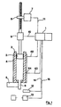
- the apparatus comprises a command and control unit 1 containing in particular the electronic microprocessor system, a cylinder 2 and a piston 3 produced in accordance with standard ASTM D 1238-82, the cylinder 2 being fitted with a thermostatically controlled liner 4 also produced in accordance with the above-mentioned standard.
- the cylinder 2 is further provided with a slide exchanger device 5 enabling this cylinder to be equipped with a die 6 adapted to the rheological measurement to be carried out.
- the displacement of the piston 3 in the cylinder 2 is ensured by a stepping motor 7 and this by means of the screw and nut systems 8.
- a force sensor device 9 which will be detailed below is arranged between the motor 7 and the piston 3 and sends by the cable 10 a signal proportional to the force exerted by the piston towards the control box 1.
- the motor 7 is controlled by the cable 11 connected to the control box 1.
- the apparatus also includes a device 12 for cutting the rod flush with the die 6, the active part of which consists of a flexible blade fixed to the end of a rotary shaft driven by an electric motor as well as an optical device 13 of detection of the rod located 70 mm from the end of the die and constituted by optical fibers arranged in a ring concentric with the axis of the cylinder 2, these two devices being connected to the control unit 1 by cables 14 and 15.
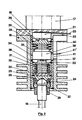
- the force sensor 9 connected between the control rod 16 of the piston 3 and the displacement control 17 controlled by the stepping motor 7, is constituted by an external casing 18 of annular and cylindrical shape containing the measuring devices and equipped at its upper part with a circular cover 19 connected directly to the movement control 17.
- the cover 19 has an internal annular rim 20 which fits into the external envelope 18 and which delimits a cylindrical cell housing or holder in which is inserted a force cell with strain gauge 21 with a measurement range from 0 to 2000 N , a light 22 being provided in the cover 19 and in the flange 20 to allow the passage of the cables 23 for connection of the force cell 21.
- the head 24 of the piston control rod 16 is held by a ball bushing 25 in an annular cylindrical piston holder 26 which can move in the outer casing 18 and which is retained downward in this outer casing by a spring ring 27.
- the head 24 of the control rod 16 of the piston also bears on a pusher 28 which itself bears on the piston holder 26 and which can drive the piston holder 26 upwards. intermediate of the spring ring 29 provided in this piston holder.
- the piston holder 26 is also provided with an assembly comprising a cup 30 and a pusher 31 kept apart from one another by a calibrated spring 32 prestressed under a tension of 100 N, the cup 30 resting on the pusher 28 and the pusher 31 being retained against the action of the calibrated spring 32 by a spring ring 33 provided in the piston holder 26.
- the outer casing 18 also contains a cylindrical cell holder 34 and of annular section provided with an internal flange 35 this cell holder 34 being located above the piston holder and slightly spaced therefrom.
- the lower part of the cell holder 34 constitutes a housing into which is inserted a force cell 36 of measurement range from 0 to 100 N which bears on the internal rim 35 and whose measurement push-button 37 is in contact with the push-button 31
- Lights 41 are provided in the outer casing 18 and in the cell holder 34 to allow the passage of the connection cables 41 'of the force cell 36.
- the cables 23 and 41' in fact constitute the cable 10 which is connected to the command and control unit.
- the upper part of the cell holder 34 located above the internal rim 35 is equipped with a calibrated spring 38 prestressed under a tension of 2000 N which bears on the internal rim 35 and tends to push back a pusher 39 which is retained in the door cell 34 by a spring ring 40 provided in this cell holder.
- the pusher 39 In the rest position, the pusher 39 is in direct contact with the pusher for measuring the force cell 21 and the ends of the cell holder 34 are separated by a predetermined clearance from the ends of the piston holder 26 and the flange 20.
- the operation of the device thus described is as follows: the device as illustrated being at rest, that is to say not subject to the action of a force to be measured.
- the command and control unit 1 which contains the electronic system which manages the measurement, control, signaling and alarm functions comprises a temperature regulator 42, a control block 47 of the stepping motor, a force regulator 50 and a microprocessor system 53.
- the temperature regulator 42 of the PID type (proportional, integral, derivative) is connected by the cable 43 to a temperature probe 44 of the Pt100 type placed in the lining 4 of the cylinder 3 and ensures the thermostatization of the lining 4 by means of 'A heating element (not shown) supplied by the cable 45. It is obvious that it is possible to have several probes spaced along the jacket 4. If a high or low temperature limit is exceeded, the temperature regulator temperature 42 sends an alarm signal to the microprocessor system 53 via the cable 46.
- the control unit 47 of the stepping motor receives an analog voltage (0-10V) coming either from the force regulator 50 (in the case of the measurement of a melting index) or from a setpoint generator (not shown ) via cables 48, 49 (in the case of a viscosity and / or swelling measurement). In the latter case the cables 48 and 49 bring a voltage corresponding either to a maximum displacement speed of the piston or to a reference speed (speed imposed by the measurement).
- An all-or-nothing input 51 determines the direction of action of the stepping motor (raising or lowering of the piston).
- the output 11 of this block supplies the power pulses necessary for controlling the stepping motor, the frequency of these pulses being proportional to the analog input voltage.
- the image of the pulses actually sent to the stepping motor is introduced into the microprocessor system where a totalizing counter (not shown) makes it possible to precisely determine the instantaneous positions of the piston driven by the stepping motor.
- the force regulator 50 is only in use when measuring a melt index. It is of the proportional-integral type. Under the control of the microprocessor system 53, it automatically makes it possible to choose gain values according to the sample to be evaluated. A “Sample and Hold” or sampler-blocker circuit 52 is provided to meet the needs of the measurement profile adopted (memorization of the voltage to be applied in the last step).
- the microprocessor system 53 consists of two distinct parts: - on the one hand, the set of industrial microprocessor cards including the processor (type 8085A), RAM and ROM memories, pulse counters, inputs and outputs to the outside and possibly an output to a printer, and / or a screen not shown.
- the processor type 8085A
- RAM random access memory
- ROM read-only memory
- pulse counters inputs and outputs to the outside and possibly an output to a printer, and / or a screen not shown.
- the inputs and outputs include in particular the cables 54, 55, 56 and 57 for output to the force regulator 50, the cable 58 for output to the control unit 47, the cable 46 for input for the temperature regulator alarm , the input cable 10 of the signal emitted by the force sensor 9, the output cable 14 to the rod cutting device 12, the input cable 15 of the rod detector 13, the input cables 59 of the fault detectors (faulty or placed die incorrectly, absence of material to be tested, etc.) and the output cables 60 to the alarm or signaling indicators.
- the set of adapter or interface cards constituting the link between the inputs and outputs to the other components. This interface adapts the level of voltages or the shape of the all-or-nothing signals (position sensors) to the requirements of microprocessor cards.
- the program introduced into the ROM memory of the microprocessor 53 comprises the measurement profile adopted, the management of the inputs / outputs, the management of the alarms and signals as well as the possible output to a printer and / or a screen.
- melt index 0.325 of an ELTEX A1050 polyethylene produced by the applicant was evaluated, the measurement being carried out according to the conditions of the standard. ASTM-D-1238-82. The test gave as result: 0.681 g / 10 min, which corresponds practically to the average melting index recorded using conventional equipment.
- Example 3 With the apparatus used in Example 3, the dynamic viscosity and the speed gradient swelling of 1000 sec ⁇ 1 (43) of an ELTEX A3999 polyethylene produced by the applicant were evaluated. The measurement carried out in 30 seconds after thermal conditioning at 190 ° gave the value: 410.01 dPa.s for the viscosity and 1.481 for the swelling. It should be noted here that, given the extreme fluidity of this resin, it is not possible to measure its swelling by the usual methods.
- thermoplastic materials are perfectly suitable for evaluating the rheological properties of thermoplastic materials either in accordance with the usual standards or according to a faster method.
Landscapes
- General Health & Medical Sciences (AREA)
- Immunology (AREA)
- Physics & Mathematics (AREA)
- General Physics & Mathematics (AREA)
- Life Sciences & Earth Sciences (AREA)
- Chemical & Material Sciences (AREA)
- Analytical Chemistry (AREA)
- Biochemistry (AREA)
- Mechanical Engineering (AREA)
- Engineering & Computer Science (AREA)
- Health & Medical Sciences (AREA)
- Pathology (AREA)
- Extrusion Moulding Of Plastics Or The Like (AREA)
- Investigating Or Analyzing Materials Using Thermal Means (AREA)
- Transition And Organic Metals Composition Catalysts For Addition Polymerization (AREA)
- Investigating Strength Of Materials By Application Of Mechanical Stress (AREA)
- Ultra Sonic Daignosis Equipment (AREA)
- Injection Moulding Of Plastics Or The Like (AREA)
- Polyesters Or Polycarbonates (AREA)
Abstract
Description
- La présente invention concerne un appareillage pour la détermination rapide et précise de propriétés rhéologiques de matières thermoplastiques telles que l'indice de fusion (melt index), les courbes viscosimétriques et/ou le gonflement à l'extrusion.
- Dans les procédés de fabrication et de mise en oeuvre des matières thermoplastiques, il importe de pouvoir disposer dans des délais très courts, d'un maximum d'informations sur les propriétés rhéologiques de ces matières afin de pouvoir contrôler efficacement ces opérations.
- On connaît certes déjà des appareillages qui permettent une évaluation rapide et même continue de certaines propriétés rhéologiques des matières thermoplastiques. Toutefois ces appareils sont spécifiques pour évaluer une propriété particulière et ils ne peuvent fonctionner selon les normes usuelles.
- Ainsi le PORPOISE Viscosimeter mis au point par GEC ELECTRICAL PROJECTS MARINE and OFFSHORE et qui comporte une pompe à engrenages en relation avec un capillaire permet certes une évaluation continue de la viscosité d'une matière thermoplastique mais cet appareillage ne peut être adapté aisément à la mesure d'une autre propriété rhéologique telle que par exemple un indice de fusion.
- La présente invention a pour objet de remédier à ces inconvénients et de fournir un appareillage universel permettant d'évaluer des propriétés rhéologiques différentes telles que des indices de fusion, des viscosités et/ou des gonflements à l'extrusion et ce soit selon les normes en vigueur et ce en un minimum de temps ou selon une méthode plus rapide mais tout aussi précise.
- La présente invention concerne dès lors un appareillage pour la détermination rapide des propriétés rhéologiques d'une matière thermoplastique comprenant :
- un boîtier de commande et de contrôle;
- un cylindre destiné à recevoir une dose déterminée de la matière thermoplastique à évaluer et équipé d'un chemisage thermostatisé pour le conditionnement thermique, durant au moins 300 secondes et à température prédéterminée, de la dose de matière thermoplastique à évaluer;
- un piston pouvant coulisser dans le cylindre de façon à s'appliquer contre la dose de matière thermoplastique;
- un système échangeur permettant d'équiper le cylindre d'une filière à capillaire adaptée à la mesure rhéologique à effectuer;
- un moteur à commande pas à pas assurant un déplacement contrôlé du piston dans le cylindre pour expulser la matière thermoplastique via la filière à capillaire et
- un capteur de force disposé entre le moteur et le piston donnant un signal en fonction de la force appliquée au piston caractérisé en ce qu'il comporte en outre un système électronique à microprocesseur contrôlant le moteur pas à pas en fonction de la position du piston et/ou du signal émis par le capteur de force de façon telle, qu'à la fin du conditionnement thermique, le piston se trouve à une distance de la filière à capillaire autorisant la mesure à effectuer et agisse, depuis un laps de temps variant de 10 à 180 secondes, sur la dose de matière thermoplastique à évaluer selon un paramètre de vitesse de déplacement ou de force appliquée imposé par le type de mesure rhéologique à effectuer. - L'appareillage conforme à l'invention peut dès lors être exploité soit pour déterminer un indice de fusion, soit une viscosité d'une matière thermoplastique simplement en l'équipant d'une filière à capillaire appropriée et en commutant le système électronique à microprocesseur soit en régulation de la force appliquée sur le piston, soit en régulation de vitesse de déplacement du piston.
- En outre, selon une variante de réalisation qui se révèle particulièrement intéressante, l'appareillage conforme à l'invention peut être équipé d'un dispositif permettant la découpe du jonc de matière thermoplastique extrudé au ras de la filière à capillaire et d'un dispositif de détection de l'extrémité menante du nouveau jonc extrudé situé à une distance prédéterminée de l'extrémité de la filière à capillaire. De ce fait, l'appareillage conforme à l'invention peut également être exploité pour déterminer, de façon connue, les caractéristiques de gonflement à l'extrusion d'une matière thermoplastique, cette mesure se faisant, en général, conjointement avec des mesures de viscosité.
- Selon un mode de réalisation qui est préféré, le dispositif de découpe du jonc extrudé est constitué par une lame flexible, fixée au bout d'un arbre rotatif qui peut être actionné automatiquement par un moteur électrique et le dispositif de détection est constitué par des fibres optiques disposées dans un anneau concentrique à l'axe du cylindre, la distance entre le dispositif de détection optique et l'extrémité de la filière à capillaire étant généralement fixée à 70 mm. Il est toutefois bien évident que ces dispositifs de découpe et de détection ne sont nullement critiques et que, dès lors, d'autres dispositifs fiables peuvent être envisagés.
- Le boîtier de commande et de contrôle contient le système électronique à microprocesseur contrôlant le moteur pas à pas, le régulateur de température ainsi que le matériel électronique nécessaire pour la gestion des séquences d'utilisation, pour les mesures, les calculs et l'affichage des résultats, etc... La face avant de ce boîtier comporte les boutons de commande et de sélection, les tableaux d'affichage et éventuellement des témoins d'alarme destinés à signaler tout fonctionnement défectueux. Le boîtier de commande peut être raccordé à une imprimante et/ou un écran qui visualisent les conditions d'essai et les résultats obtenus.
- Selon un mode de réalisation avantageux, le cylindre, le chemisage thermostatisé et le piston de l'appareillage selon l'invention sont réalisés en conformité avec la norme ASTM D 1238-82 de façon à permettre des mesures normalisées en ce qui concerne la détermination des indices de fusion.
- Dans le même but, le dispositif échangeur de filières qui peut être du type à tiroir ou à tourelle est, de préférence conçu pour être garni d'un jeu de filières normalisés soit d'une filière L/D:8/2,095 pour des mesures d'indice de fusion et de filières L/D:15/1 et 30/2 pour des mesures de viscosité et/ou de gonflement. De préférence, le dispositif échangeur de filières est équipé de détecteurs de proximité assurant un contrôle du choix correct de la filière en fonction de la propriété rhéologique à effectuer et contrôlant la mise en place correcte de cette filière sur le cylindre. Ces détecteurs peuvent activer des témoins d'alarme prévus sur le boîtier de commande et de contrôle.
- Ainsi qu'il a été précisé, le déplacement du piston dans le cylindre est assuré par un moteur à commande pas à pas dont les impulsions de commande sont contrôlées par le système électronique à microprocesseur. L'entraînement du piston par ce moteur est, de préférence assuré par un système à vis et écrou. Selon un mode de réalisation qui est préféré le système de transmission et le moteur sont choisis de façon telle qu'un déplacement linéaire du piston de 1.10⁻³ m requiert de 500 à 10 000 et de préférence de 1000 à 3 000 impulsions de commande du moteur. De cette façon, la position du piston peut être déterminée à tout moment avec une précision du l'ordre de 0,5.10⁻⁶ m.
- Le capteur de force, disposé entre le moteur à commande pas à pas et le piston est, de préférence, équipé d'éléments de mesures constituées par des cellules de force à jauge de contrainte.
- Etant donné que les mesures rhéologiques réalisables au moyen de l'appareillage selon l'invention peuvent exiger l'application sur le piston de forces pouvant varier de quelques Newtons à plusieurs milliers de Newtons tant lors des mesures que durant le conditionnement thermique, il n'est pas possible d'utiliser une seule cellule de force pour assurer dans tous les cas d'utilisation une mesure continue et précise de ces forces. Dans la pratique, on fait, dès lors, appel à une pluralité de cellules de force ayant des gammes de mesures étagées.
- Ainsi, par exemple, on peut avantageusement utiliser une cellule de force de gamme 0-100 N et une cellule de force de gamme 0-2 000 N, ces deux cellules étant fixées sur une potence pivotante permettant la mise en service alternée de l'une ou de l'autre cellule selon la mesure rhéologique à effectuer et selon la matière thermoplastique à évaluer.
- Dans ce cas, il peut se révéler intéressant de prévoir une troisième position pour la potence, position dans laquelle les deux cellules de force sont hors service et écartées de l'axe du cylindre de façon à permettre un accès aisé au cylindre par exemple lors d'une opération de nettoyage.
- Selon un mode de réalisation qui est préféré, le capteur de force est constitué par une pluralité de cellules de force disposées en série et de gamme de mesures croissante, chaque cellule de force étant insérée dans un boîtier qui assure le transfert de l'effort exercé sur la cellule de force qu'il contient à la suivante de gamme de mesures plus élevée lorsque cet effort dépasse la valeur maximum acceptable pour cette cellule de force.
- A cet effet et selon un mode de réalisation particulièrement apprécié, chaque cellule de force successive est insérée dans un boîtier résistant ouvert, les divers boîtiers étant superposés. Le dimensionnement de chaque boîtier est réalisé de façon telle que la paroi latérale d'un boîtier vient en contact avec le fond fermé du boîtier précédant ou suivant dès que la valeur de l'effort transmis à la cellule de force insérée dans ce boîtier atteint la valeur maximum acceptable pour cette cellule de force, la cellule de force insérée dans le boîtier précédant ou suivant, de gamme de mesures plus élevée assurant alors la reprise de l'effort à mesurer.
- Selon un mode de réalisation qui est préféré dans ce cas chaque cellule de force est, en outre, protégée mécaniquement par un système de transmission de la force à mesurer constitué par un ressort taré précontraint à la valeur maximum acceptable pour chaque cellule de force qui assure la transmission de l'effort à mesurer. De cette façon, lorsque la force appliquée à une cellule de force quelconque risque de dépasser la valeur maximum acceptable, la déformation du ressort taré correspondant empêche l'application d'une force excessive sur la cellule de force.
- En utilisant un capteur de force équipé de cellules de force en série qui vient d'être décrit, on évite en particulier tout accident pouvant découler d'une force excessive transmise accidentellement en système de mesure de la force.
- En outre, ainsi qu'il sera expliqué plus loin, le recours à un tel capteur de force permet d'effectuer des mesures rhéologiques sur des matières thermoplastiques très différentes en utilisant toujours une dose identique de la matière thermoplastique à évaluer.
- Conformément à l'invention, l'appareillage comporte en outre un système électronique à microprocesseur qui contrôle en continu le moteur à commande pas à pas et partant les déplacements du piston et/ou la force appliquée sur celui-ci et ce en fonction de la position occupée à chaque instant par le piston et/ou en fonction du signal émis par le capteur de force tant durant la phase de conditionnement thermique que lors de la mesure rhéologique de la matière thermoplastique à évaluer de façon telle qu'à la fin du conditionnement thermique le piston se trouve à une distance de la filière à capillaire autorisant la mesure à effectuer et agisse depuis un laps de temps variant de 10 à 180 secondes sur la matière plastique à évaluer selon des paramètres de vitesse de déplacement ou de force appliquée imposés par le type de mesure rhéologique à effectuer, ces paramètres étant en outre maintenus constants pendant toute la durée de la mesure.
- En fait, lors d'une mesure d'indice de fusion, le piston doit nécessairement appliquer une force constante prédéterminée sur la matière thermoplastique puisque une telle mesure revient à déterminer le poids de matière plastique qui est expulsé par une filière à capillaire déterminée, en un temps donné et sous l'application d'une force déterminée tandis que lors d'une mesure de viscosité ou de gonflement le piston doit être animé d'une vitesse de déplacement constante et prédéterminée durant toute la mesure. Il apparaît donc que le système électronique à microprocesseur doit assurer soit une régulation de force soit une régulation de vitesse selon la mesure rhéologique à effectuer. En outre pour obtenir des résultats reproductibles on sait que les mesures rhéologiques doivent toujours être débutées lorsque le piston atteint une distance prédéterminée de la filière à capillaire, cette distance étant généralement fixée à 50 mm.
- Lors de la mesure d'indice de fusion, le système électronique doit assurer la régulation de la force appliquée au piston, le cylindre étant dans ce cas équipé d'une filière adaptée pour la mesure d'un indice de fusion.
- Lors d'une telle mesure, le système électronique, dans une première étape, après 5 à 30 secondes de conditionnnement thermique de la dose de matière thermoplastique à évaluer, contrôle le moteur à commande pas à pas de façon telle que le piston durant 50 à 150 secondes applique sur la dose de matière plastique une force constante égale à celle devant être appliquée durant la mesure à effectuer, évalue la vitesse de déplacement du piston sous l'effet de cette force et détermine les paramètres de régulation idéaux en fonction de la matière thermoplastique examinée, dans une seconde étape, contrôle le moteur à commande pas à pas de façon telle que la force appliquée au piston est réduite ou accrue durant un certain laps de temps et, dans une troisième étape, après 120 à 290 secondes de conditionnement thermique contrôle le moteur à commande pas à pas de façon telle que le piston applique de nouveau sur la dose de matière thermoplastique à évaluer une force égale à la force devant être appliquée durant la mesure, la troisième étape étant initiée à un instant tel que l'application de cette force amène le piston à la distance prédéterminée de la filière autorisant la mesure à la fin du délai imparti pour le conditionnement thermique, cette force étant maintenue constante pendant toute la durée de la mesure subséquente.
- L'appareillage conforme à l'invention se distingue, dès lors des appareillages de l'art antérieur par le fait que la consigne à respecter durant la mesure rhéologique à effectuer, dans le cas présent la constance de la force appliquée par le piston, est déjà respectée avant la mesure de telle sorte que le piston, à la fin du conditionnement thermique non seulement se trouve à la distance de la filière autorisant la mesure à effectuer mais encore est soumis à la consigne imposée pour la mesure depuis un certain laps de temps.
- De cette façon, l'appareillage lors de son utilisation en phase de mesure se trouve en régime stable d'écoulement dès le début de la mesure.
- En outre, tout comme les appareillages connus, l'appareillage selon l'invention permet d'effectuer la mesure rhéologique souhaitée à la fin du délai imparti pour le conditionnement thermique de la matière thermoplastique à évaluer.
- Selon une variante de réalisation, qui est préférée lorsqu'on ne dispose au préalable d'aucune indication sur les caractéristiques rhéologiques de la matière thermoplastique à évaluer, après 5 à 30 secondes de conditionnement thermique le système électronique durant le début de la première étape contrôle d'abord le moteur à commande pas à pas de façon telle que le piston applique tout d'abord sur la dose de matière thermoplastique une force nettement inférieure à la force devant être appliquée durant la mesure et ce durant 10 à 90 secondes de façon à permettre une première évaluation du gain du système électronique et sur cette base une estimation de la durée idéale de la phase suivante de la première étape durant laquelle le système électronique, via le moteur de commande pas à pas, applique sur la dose de matière thermoplastique une force égale à celle devant être appliquée durant la mesure rhéologique à effectuer.
Il a en effet été constaté que les paramètres de fonctionnement du système électronique sont sensiblement fonction de la nature de la matière thermoplastique à évaluer et dépendent peu de la force appliquée pour déterminer ces paramètres. Il en résulte donc que la connaissance du gain du système électronique pour une force appliquée donnée permet le calcul du gain pour une force appliquée différente avec une bonne approximation. - En d'autres termes, la connaissance de la vitesse de déplacement du piston sous l'action d'une faible force (1 à 20 N) permet d'évaluer la vitesse de déplacement du piston sous une force plus élevée à appliquer lors de la mesure et partant de déterminer une durée d'application de cette force durant la première étape compatible avec une amenée du piston à la distance prédéterminée de la filière à la fin du conditionnement thermique.
- Durant cette premiére étape, l'appareillage procède à une nouvelle évaluation de la vitesse de déplacement réelle du piston lorsque celui-ci est soumis à la force à appliquer durant la mesure.
- Selon la matière thermoplastique à évaluer, cette vitesse de déplacement du piston est soit trop élevée (matière thermoplastique fluide) soit trop faible (matière thermoplastique visqueuse) pour amener le piston à la distance prédéterminée de la filière à la fin du temps imparti pour le conditionnement thermique.
- Dans le premier cas, durant la seconde étape, le système électronique contrôle le moteur à commande pas à pas de façon à réduire la force appliquée au piston durant un laps de temps tel qu'après écoulement de ce temps, le système électronique puisse à nouveau, via le moteur à commande pas à pas, appliquer au piston, durant la troisième étape, la force à utiliser pour la mesure rhéologique à effectuer et amener ainsi ce piston à la distance prédéterminée de la filière à la fin du temps imparti par le conditionnement thermique. Selon un mode de réalisation préféré, durant la seconde étape, la force appliquée au piston est réduite à zéro, le moteur à commande pas à pas n'étant plus excité, ceci afin de réduire au minimum la durée de la seconde étape et partant d'allonger celle de la troisième étape.
- Dans le second cas, durant la seconde étape, le système électronique contrôle le moteur à commande pas à pas de façon à accroître la force appliquée au piston durant un laps de temps tel qu'après écoulement de ce temps, le système électronique puisse à nouveau, via le moteur à commande pas à pas, appliquer au piston, durant la troisième étape , la force à utiliser pour la mesure rhéologique à effectuer et amener celui-ci à la distance prédéter minée de la filière à la fin du temps imparti pour le conditionnement thermique. Selon un mode de réalisation préféré, durant la seconde étape, la force appliquée au piston est la force maximale pouvant être supportée par l'appareillage, ceci de nouveau afin de raccourcir la durée de la seconde étape et partant d'accroître celle de la troisième.
- Avec l'appareillage selon l'invention, il est donc possible d'effectuer des mesures d'indices de fusion dès la fin du conditionnement thermique et ce dans d'excellentes conditions puisque la consigne à respecter durant la mesure - force constante appliquée au piston - et déjà satisfaite avant le début de la mesure et que l'appareillage se trouve donc déjà en régime.
- Les indices de fusion sont déterminées à partir de la vitesse de déplacement du piston soumis à la force constante imposée.
- La détermination des indices de fusion sous les charges usuelles 3,19 N (0,325 kgf), 21,18 N (2,16 kgf), 49,03 N (5 kgf) ou 211,8 N (21,6 kgf) peut en outre être effectuée conformément à la norme ASTM D1238-82 méthode A c'est-à-dire avec une durée de mesure variant de 330 à 660 secondes selon la fluidité à chaud de la matière thermoplastique à évaluer lorsque, ainsi qu'il est préféré, on utilise un appareillage comportant un ensemble - cylindre, piston, filière - en conformité avec cette norme.
- Toutefois, compte tenu du fait que le recours à un moteur à commande pas à pas permet une détermination très précise des positions successives du piston et que le système électronique permet de débuter les mesures dans des conditions idéales il a été constaté que des indices de fusion déterminés dans un laps de temps de mesure nettement plus court, de l'ordre de 10 à 60 secondes et même moins sont parfaitement comparables à ceux obtenus selon la méthode imposée par la norme précitée et ce avec une reproductibilité remarquable.
- En pratique, avec l'appareillage conforme à l'invention, la demanderesse détermine habituellement des indices de fusion en 30 secondes qui sont en parfaite corrélation avec ceux déterminés selon la norme ASTM précitée.
- L'appareillage conforme à l'invention se révèle, dès lors, particulièrement intéressant pour effectuer des mesures de contrôle régulières et rapides dans une installation de production ou de mise en oeuvre de matières thermoplastiques et plus particulièrement de polyoléfines.
- Selon un mode d'exploitation de l'appareillage selon l'invention qui se révèle intéressant, on règle celui-ci de façon telle qu'il effectue au moins trois mesures successives de durées égales durant le temps imparti pour la mesure et effectue une comparaison entre ces mesures et leur moyenne en vue de détecter un éventuel écart important (supérieur à 25%) rendant la détermination suspecte.
- Lorsque l'appareillage selon l'invention est équipé d'un capteur de force équipé de cellules de force en série ainsi qu'il est préféré, la force appliquée au piston lors du conditionnement thermique durant la seconde étape peut varier dans de très larges limites et, dès lors, la dose de matière thermoplastique à introduire dans le cylindre, lors d'une mesure, peut être constante quel que soit l'indice de fusion de cette matière.
- Cette particularité de l'appareillage conforme à l'invention se révèle très intéressante dans le cas où l'on désire automatiser le fonctionnement pour effectuer des séries de mesures successives sur des matières thermoplastiques par exemple à titre de contrôles périodiques dans une installation de fabrication.
- Le système électronique à microprocesseur, dans ce cas, assure la régulation de la vitesse de déplacement du piston, ce cylindre étant équipé d'une filière adaptée pour la mesure à effectuer.
- Lors d'une telle mesure, le système électronique, après 5 à 30 secondes de conditionnement thermique de la dose de matière thermoplastique à évaluer, détermine, en fonction de la position du piston en contact avec la dose et du temps de conditionnement imparti, la vitesse moyenne à imposer au déplacement du piston pour amener celui-ci à la distance prédéterminée de la filière à la fin du délai imparti pour le conditionnement thermique et compare cette vitesse moyenne à la vitesse constante à imposer au piston pour la mesure à effectuer, puis dans une première étape, le système électronique, en fonction du résultat de cette comparaison, contrôle le moteur à commande pas à pas de façon telle que le piston se déplace à une vitesse plus faible ou plus élevée que cette vitesse et, dans une seconde étape, contrôle le moteur à commande pas à pas de façon telle que le piston se déplace à la vitesse constante imposée pour la mesure à effectuer, cette seconde étape étant initiée à un instant tel que cette vitesse constante de déplacement du piston amène celui-ci à la distance prédéterminée de la filière à la fin du délai imparti pour le conditionnement thermique, cette vitesse constante de déplacement du piston étant maintenue pendant toute la durée de la mesure à effectuer.
- Dans la seconde étape, le système électronique impose une vitesse de déplacement plus faible que la vitesse moyenne lorsque la vitesse constante de déplacement à imposer au piston pour la mesure à effectuer est supérieure à cette vitesse moyenne et, par contre, impose au piston une vitesse de déplacement plus élevée que la vitesse moyenne dans le cas contraire.
- Afin de réduire la durée de la première étape et partant d'allonger celle de la seconde étape, il est préféré, durant la première étape, d'imposer au piston une vitesse de déplacement aussi faible ou aussi élevée que possible. Dans la pratique on préfère soit une vitesse de déplacement nulle par un arrêt du moteur à commande pas à pas, soit une vitesse de déplacement aussi élevée que possible compatible avec la résistance mécanique de l'appareillage.
- L'appareillage conforme à l'invention se distingue donc une nouvelle fois des appareillages déjà connus par le fait que la consigne à respecter durant la mesure à effectuer, dans le cas présent une vitesse de déplacement du piston constante et prédéterminée est déjà respectée avant la mesure de telle sorte que, lorsque le piston se trouve, à la fin du conditionnement thermique, à la distance de la filière autorisant la mesure à effectuer, celui-ci est animé depuis un certain temps de la vitesse imposée pour la mesure à effectuer. L'appareillage, lors de son utilisation en phase de mesure, se trouve donc de nouveau en régime stable d'écoulement dès le début de la mesure à effectuer. La mesure de viscosité est calculée à partir de la force exercée sur le piston pour maintenir la vitesse imposée.
- Selon un mode de réalisation de l'appareillage qui est préféré dans les 30 secondes qui précèdent le moment où le piston atteint la distance prédéterminée de la filière, celui-ci effectue une pluralité de mesures successives de la force appliquée sur le piston par l'intermédiaire du capteur de force et compare ces mesures entre elles et avec leur moyenne de façon à détecter tout écart important, par exemple de plus de 5 %, augurant d'une éventuelle instabilité d'écoulement, c'est-à-dire d'un écoulement oscillant qui est susceptible de fausser la mesure à effectuer. Dans ce dernier cas, la séquence de mesure est interrompue et un témoin d'alarme prévu sur la face avant du boîtier de commande de l'appareillage peut signaler à l'opérateur la raison de cette interruption.
- L'appareillage selon l'invention permet donc de déterminer la viscosité dynamique de toute matière plastique et ce sous un gradient de vitesse quelconque, la mesure pouvant être effectuée en 30 secondes ou dans un délai plus court et ce avec une précision remarquable.
- Pour effectuer simultanément une mesure complémentaire de gonflement à l'extrusion, le jonc extrudé par la filière est découpé au ras de celle-ci dès que le piston atteint la distance prédéterminée de la filière et le détecteur est mis en service. Dès que l'extrémité menante du jonc extrudé atteint le détecteur, l'appareillage peut calculer le gonflement et afficher celui-ci sur la face avant du boîtier de commande. Ce gonflement est déterminé à partir de l'espace parcouru par le piston au moment de la détection du nouveau jonc.
- Le système électronique à microprocesseur peut être réalisé de façon quelconque pour autant qu'il assure les régulations décrites ci-avant.
- En général ce système comporte :
- un système à microprocesseur qui programme et gère les différentes séquences de mesure;
- un bloc de commande du moteur pas à pas qui, sous le contrôle du microprocesseur, reçoit une tension analogique de commande provenant soit d'un régulateur de force, dans le cas d'une mesure d'indice de fusion, soit d'un générateur de consigne, dans le cas d'une mesure de viscosité et/ou de gonflement et dont la sortie fournit au moteur les impulsions de commande nécessaires à son fonctionnement et
- un régulateur de force, mis uniquement en service lors de la mesure d'un indice de fusion, que est du type proportionnel-intégral et qui utilise les valeurs de gain choisies automatiquement sous le contrôle du système à microprocesseur. - L'appareillage conforme à l'invention est en outre explicité plus en détail par l'exemple de réalisation pratique donné ci-après et dans la description duquel on se réfèrera aux figures annexées dans lesquels :
- - la fig. 1 est un schéma de l'appareillage conforme à l'invention;
- - la fig. 2 est une vue en coupe d'un capteur de force équipé de deux cellules de force en série;
- - la fig. 3 est un schéma du boîtier de commande et de contrôle.
- Ainsi qu'il apparaît sur le schéma de la fig. 1, l'appareillage conforme à l'invention comporte un boîtier de commande et de contrôle 1 contenant notamment le système électronique à microprocesseur, un cylindre 2 et un piston 3 réalisés en conformité avec la norme ASTM D 1238-82, le cylindre 2 étant équipé d'un chemisage thermostatisé 4 réalisé également en conformité avec la norme précitée.
- Le cylindre 2 est en outre pourvu d'un dispositif échangeur à tiroir 5 permettant d'équiper ce cylindre d'une filière 6 adaptée à la mesure rhéologique à effectuer.
- Le déplacement du piston 3 dans le cylindre 2 est assuré par moteur à commande pas à pas 7 et ce par l'intermédiaire du systèmes à vis et écrou 8.
- Un dispositif capteur de force 9 qui sera détaillé plus loin est disposé entre le moteur 7 et le piston 3 et envoie par le câble 10 un signal proportionnel à la force exercée par le piston vers le boîtier de commande 1. Le moteur 7 est commandé par le câble 11 raccordé au boîtier de commande 1.
- L'appareillage comporte également un dispositif 12 de découpe du jonc au ras de la filière 6 dont la partie active est constituée d'une lame flexible fixée au bout d'un arbre rotatif entraîné par un moteur électrique ainsi qu'un dispositif optique 13 de détection du jonc situé à 70 mm de l'extrémité de la filière et constitué par des fibres optiques disposées dans un anneau concentrique à l'axe du cylindre 2, ces deux dispositifs étant raccordés au boîtier de commande 1 par des câbles 14 et 15.
- Ainsi qu'il apparaît plus particulièrement sur la figure 2, le capteur de force 9 connecté entre la tige de commande 16 du piston 3 et la commande de déplacement 17 contrôlée par le moteur pas à pas 7, est constitué par une enveloppe externe 18 de forme annulaire et cylindrique contenant les dispositifs de mesure et équipée à sa partie supérieure d'un couvercle circulaire 19 raccordé directement à la commande de déplacement 17.
- Le couvercle 19 présente un rebord annulaire interne 20 qui s'emboîte dans l'enveloppe externe 18 et qui délimite un boîtier ou porte cellule cylindrique dans lequel est insérée une cellule de force à jauge de contrainte 21 de gamme de mesure de 0 à 2000 N, une lumière 22 étant prévue dans le couvercle 19 et dans le rebord 20 pour permettre le passage des câbles 23 de connexion de la cellule de force 21.
- La tête 24 de la tige de commande 16 du piston est maintenue par une douille à billes 25 dans un porte piston 26 annulaire d'allure cylindrique pouvant se déplacer dans l'enveloppe externe 18 et qui est retenu vers le bas dans cette enveloppe externe par un anneau-ressort 27. La tête 24 de la tige de commande 16 du piston prend en outre appui sur un poussoir 28 qui prend lui-même appui sur le porte piston 26 et qui peut entraîner le porte piston 26 vers le haut par l'intermédiaire de l'anneau-ressort 29 prévu dans ce porte piston.
- Le porte piston 26 est également pourvu d'un ensemble comprenant une coupelle 30 et un poussoir 31 maintenus écartés l'un de l'autre par un ressort taré 32 précontraint sous une tension de 100 N, la coupelle 30 prenant appui sur le poussoir 28 et le poussoir 31 étant retenu contre l'action du ressort taré 32 par un anneau-ressort 33 prévu dans le porte piston 26.
- L'enveloppe externe 18 contient également un porte cellule 34 cylindrique et de section annulaire pourvu d'un rebord interne 35 ce porte cellule 34 étant situé au dessus du porte piston et légèrement écarté de celui-ci.
- La partie inférieure du porte cellule 34 constitue un boîtier dans lequel est insérée une cellule de force 36 de gamme de mesure de 0 à 100 N qui prend appui sur le rebord interne 35 et dont le poussoir de mesure 37 est en contact avec le poussoir 31. Des lumières 41 sont prévues dans l'enveloppe externe 18 et dans le porte cellule 34 pour permettre le passage des câbles de connexion 41' de la cellule de force 36. Les câbles 23 et 41' constituent en fait le câble 10 qui est raccordé au boîtier de commande et de contrôle.
- La partie supérieure du porte cellule 34 située au dessus du rebord interne 35 est équipée d'un ressort taré 38 précontraint sous une tension de 2000 N qui prend appui sur le rebord interne 35 et tend à repousser un poussoir 39 qui est retenu dans le porte cellule 34 par un anneau-ressort 40 prévu dans ce porte cellule.
- En position de repos, le poussoir 39 est en contact direct avec le poussoir de mesure de la cellule de force 21 et les extrémités du porte cellule 34 sont écartés par un jeu prédéterminé des extrémités du porte piston 26 et du rebord 20.
- Le fonctionnement du dispositif ainsi décrit est le suivant : le dispositif tel que illustré étant en repos c'est-à-dire non soumis à l'action d'une force à mesurer.
- Sous l'action d'une telle force, la tige de commande 16 du piston tend, par sa tête 24, à pénétrer dans l'enveloppe externe 18. Cet effort est ainsi transmis via le poussoir 28, le porte piston 26 et le poussoir 31 à la cellule de force 36 qui émet, dès lors, un signal proportionnel à cette force.
- Dès que la force à mesurer dépasse 100 N, le ressort 32 s'écrase et la force transmise à la cellule de force reste à une valeur de 100 N ce qui empêche toute détérioration de cette cellule.
- Compte tenu du fait que le jeu prévu entre le porte piston 26 et le porte cellule 34 est calculé de façon telle que ces deux éléments entrent en contact dès que la force à mesurer atteint 100N, toute force exercée supérieure à cette valeur reste, dès lors, transmise via le porte-piston 26, le porte cellule 34 et le poussoir 39 à la cellule de force 21 qui à son tour émet un signal proportionnel à cette force.
- Enfin, si l'effort exercé par la tige de commande 16 du piston dépasse accidentellement 2000 N, le ressort 38 s'écrase à son tour et la force transmise à la cellule de force 21 reste à la valeur maximum de 2000 N. Compte tenue du fait que le jeu entre le porte cellule 34 et le rebord 20 est calculé de façon telle que ces deux éléments entrent en contact dès que la force à mesurer atteint 2000 N, une force exercée par le piston qui accidentellement excéderait 2000 N serait dès lors reprise par le couvercle 19 sans aucun risque de détérioration mécanique des cellules de force 21 et 36.
- Ainsi qu'il apparaît sur le schéma de la fig. 3, le boîtier de commande et de contrôle 1 qui contient le système électronique qui gère les fonctions de mesure, de commande, de signalisation et d'alarme comprend un régulateur de température 42, un bloc de commande 47 du moteur pas à pas, un régulateur de force 50 et un système à microprocesseur 53.
- Le régulateur de température 42 du type PID (proportionnel, intégral, dérivée) est raccordé par le câble 43 à une sonde de température 44 du type Pt100 disposée dans le chemisage 4 du cylindre 3 et assure la thermostatisation du chemisage 4 par l'intermédiaire d'un élément chauffant (non représenté) alimenté par le câble 45. Il est bien évident que l'on peut disposer plusieurs sondes espacées le long du chemisage 4. En cas de dépassement d'une limite haute ou basse de température, le régulateur de température 42 envoie un signal d'alarme vers le système à microprocesseur 53 via le câble 46.
- Le bloc de commande 47 du moteur pas à pas reçoit une tension analogique (0-10V) provenant soit du régulateur de force 50 (dans le cas de la mesure d'un indice de fusion) soit d'un générateur de consigne (non représenté) via les câbles 48, 49 (dans le cas de la mesure d'une viscosité et/ou d'un gonflement). Dans ce dernier cas les câbles 48 et 49 amènent une tension correspondant soit à une vitesse de déplacement maximum du piston soit à une vitesse de consigne (vitesse imposée par la mesure). Une entrée tout ou rien 51 détermine le sens d'action du moteur pas à pas (montée ou descente du piston).
- La sortie 11 de ce bloc fournit les impulsions de puissance nécessaires à la commande du moteur pas à pas, la fréquence de ces impulsions étant porportionnelle à la tension analogique d'entrée.
- L'image des impulsions réellement envoyées au moteur pas à pas est introduite dans le système à microprocesseur où un compteur totalisateur (non représenté) permet de déterminer avec précision les positions instantanées du piston mu par le moteur pas à pas.
- Le régulateur de force 50 est uniquement en service lors de la mesure d'un indice de fusion. Il est du type proportionnel-intégral. Sous le contrôle du système à microprocesseur 53 il permet automatiquement de choisir des valeurs de gain en fonction de l'échantillon à évaluer. Un circuit "Sample and Hold" ou échantillonneur-bloqueur 52 est prévu pour satisfaire les besoins du profil de mesure adopté (mémorisation de la tension à appliquer dans la dernière étape).
- Le système à microprocesseur 53 est constitué de deux parties distinctes :
- d'une part, l'ensemble de cartes industrielles à microprocesseurs comprenant le processeur (type 8085A), les mémoires RAM et ROM, les compteurs d'impulsion, les entrées et sorties vers l'extérieur et éventuellement une sortie vers une imprimante et/ou un écran non représentés.
Les entrées et sorties comprennent notamment les câbles 54, 55, 56 et 57 de sortie vers le régulateur de force 50, le câble 58 de sortie vers le bloc de commande 47, le câble 46 d'entrée pour l'alarme du régulateur de température, le câble 10 d'entrée du signal émis par le capteur de force 9, le câble de sortie 14 vers le dispositif 12 de découpe du jonc, le câble d'entrée 15 du détecteur de jonc 13, les câbles d'entrée 59 des détecteurs de défauts (filière défectueuse ou placée incorrectement, absence de matériau à tester, etc) et les câbles de sorties 60 vers les témoins d'alarme ou de signalisation.
- d'autre part, l'ensemble de cartes d'adaptation ou d'interface constituant le lien entre les entrées et sorties vers les autres constituants. Cet interface adapte le niveau des tensions ou la forme des signaux tout ou rien (capteurs de positions) aux exigences des cartes à microprocesseur. - Le programme introduit dans la mémoire ROM du microprocesseur 53 comprend le profil de mesure adopté, la gestion des entrées/sorties, la gestion des alarmes et des signalisations ainsi que la sortie éventuelle vers une imprimante et/ou un écran.
- Avec l'appareillage tel que décrit on a réalisé un grand nombre d'essais qui ont fait apparaître que celui-ci est très précis et parfaitement fiable.
- Une sélection parmi ces essais est donnée ci-après à titre d'exemples illustratifs.
- Avec l'appareil décrit on a évalué l'indice de fusion 2,16 d'un polyéthylène ELTEX B4020 produit par la demanderesse.
- La mesure a été effectuée en 30 secondes après le conditionnement thermique à 190°C et a donné comme valeur : 2,078 gr/10 min. Un essai parallèle effectué selon la Norme ASTM D 1238-82 au moyen d'un appareil classique (Meltindexer CEAST 6542/000) a donné comme valeur 2,05±0,06 g/10 min.
- Un troisième essai effectué sur l'appareillage décrit mais dans lequel la mesure a été effectuée selon les conditions de la norme ASTM D 1235-82 a donné comme valeur 2,005 g/10 min.
- Avec l'appareillage décrit, on a évalué l'indice de fusion 0,325 d'un polyéthylène ELTEX A1050 produit par la demanderesse, la mesure étant effectuée selon les conditions de la norme ASTM-D-1238-82. L'essai a donné comme résultat : 0,681 g/10 min ce qui correspond pratiquement a l'indice de fusion moyen relevé à l'aide d'appareillages classiques.
- Avec l'appareillage décrit équipé d'une filière L/D = ¹⁵/1 on évalue la viscosité dynamique et le gonflement à gradient de vitesse de 100 sec⁻¹ (42) d'un polyéthylène ELTEX A1050 produit par la demanderesse. La mesure effectuée en 30 secondes après le conditionnement thermique à 190° a donné comme valeur 7385,23 dPa.s pour la viscosité et 1,339 pour le gonflement.
- Un essai parallèle effectuée au moyen d'un viscosimètre CIL (Canadian Ind. Ltd) a donné comme valeur de viscosité : 7480 ± 250 dPA.s.
- Avec l'appareillage utilisé à l'exemple 3 on a évalué la viscosité dynamique et le gonflement à gradient de vitesse de 1000 sec⁻¹ (43) d'un polyéthylène ELTEX A3999 produit par la demanderesse. La mesure effectuée en 30 secondes après le conditionnement thermique à 190° a donné comme valeur : 410,01 dPa.s pour la viscosité et 1,481 pour le gonflement. Il convient ici de noter que compte tenu de la fluidité extrême de cette résine, il n'est pas possible de mesurer son gonflement par les méthodes usuelles.
- Un essai parallèle effectué au moyen d'un viscosimètre CIL a donné comme valeur de viscosité : 400 ± 25 dPa.s.
- Avec l'appareillage décrit équipé d'une filière L/D : 30/2 on a évalué la viscosité dynamique et le gonflement à gradient de vitesse de 100 sec⁻¹ (42) d'un polyéthylène ELTEX B3002 produit par la demanderesse.
- La mesure effectuée en 30 secondes après le conditionnement thermique à 190° a donné comme valeur : 17538,5 dPa.s pour la viscosité et 1,539 pour le gonflement.
- Un essai parallèle effectué au moyen d'un viscosimètre GOTTFERT HKV 2000 a donné comme valeur de viscosité : 17500 ± 350 dPa.s.
- Il apparaît en conséquence que l'appareillage conforme à l'invention convient parfaitement pour évaluer les propriétés rhéologiques des matières thermoplastiques soit en conformité avec les normes usuelles soit selon une méthode plus rapide.
Claims (10)
- un boîtier de commande et de contrôle (1)
- un cylindre (2) destiné à recevoir une dose déterminée de la matière thermoplastique à évaluer et équipé d'un chemisage thermostatisé (4) pour le conditionnement thermique, durant au moins 300 secondes et à température prédéterminée, de la dose de matière thermoplastique à évaluer
- un piston (3) pouvant coulisser dans le cylindre (2) de façon à s'appliquer contre la dose de matière thermoplastique
- un système échangeur (5) permettant d'équiper le cylindre d'une filière à capillaire (6) adaptée à la mesure rhéologique à effectuer
- un moteur à commande pas à pas (7) assurant un déplacement contrôlé du piston (3) dans le cylindre (2) pour expulser la matière thermoplastique via la filière à capillaire (6) et
- un capteur de force (9) disposé entre le moteur (7) et le piston (3) donnant un signal en fonction de la force appliquée au piston (3) caractérisé en ce qu'il comporte, en outre, un système électronique à microprocesseur contrôlant le moteur à commande pas à pas (7) en fonction de la position du piston (3) et/ou du signal émis par le capteur de force (9) de façon telle qu'à la fin du conditionnement thermique, le piston (3) se trouve à une distance de la filière à capillaire (6) autorisant la mesure à effectuer et agisse depuis un laps de temps variant de 10 à 180 secondes sur la dose de matière thermoplastique à évaluer selon un paramètre de vitesse de déplacement ou de force appliquée imposé par le type de mesure rhéologique à effectuer.
Priority Applications (1)
| Application Number | Priority Date | Filing Date | Title |
|---|---|---|---|
| AT86201191T ATE48700T1 (de) | 1985-07-18 | 1986-07-08 | Geraet zur schnellen ermittlung der rheologischen eigenschaften von thermoplastischen stoffen. |
Applications Claiming Priority (2)
| Application Number | Priority Date | Filing Date | Title |
|---|---|---|---|
| FR8511146A FR2585130B1 (fr) | 1985-07-18 | 1985-07-18 | Appareillage pour la determination rapide des proprietes rheologiques de matieres thermoplastiques |
| FR8511146 | 1985-07-18 |
Publications (2)
| Publication Number | Publication Date |
|---|---|
| EP0210689A1 true EP0210689A1 (fr) | 1987-02-04 |
| EP0210689B1 EP0210689B1 (fr) | 1989-12-13 |
Family
ID=9321499
Family Applications (1)
| Application Number | Title | Priority Date | Filing Date |
|---|---|---|---|
| EP86201191A Expired EP0210689B1 (fr) | 1985-07-18 | 1986-07-08 | Appareillage pour la détermination rapide des propriétés rhéologiques de matières thermoplastiques |
Country Status (12)
| Country | Link |
|---|---|
| US (1) | US4680958A (fr) |
| EP (1) | EP0210689B1 (fr) |
| JP (1) | JPS6221040A (fr) |
| KR (1) | KR940008080B1 (fr) |
| AT (1) | ATE48700T1 (fr) |
| AU (1) | AU578370B2 (fr) |
| CA (1) | CA1257699A (fr) |
| DE (1) | DE3667540D1 (fr) |
| ES (1) | ES2000350A6 (fr) |
| FR (1) | FR2585130B1 (fr) |
| IN (1) | IN167028B (fr) |
| MX (1) | MX168433B (fr) |
Cited By (7)
| Publication number | Priority date | Publication date | Assignee | Title |
|---|---|---|---|---|
| GB2210466A (en) * | 1987-10-01 | 1989-06-07 | Alan George | Rheometrics and melt flow index |
| US5016467A (en) * | 1989-06-07 | 1991-05-21 | Amoco Corporation | Automated flow rate machine |
| EP0489662A1 (fr) * | 1990-12-06 | 1992-06-10 | Ascometal | Procédé et dispositif de mesure des caractéristiques rhéologiques d'un matériau à une température déterminée |
| EP0483619A3 (en) * | 1990-10-30 | 1992-09-23 | Shimadzu Corporation | Capillary rheometer |
| CN102713559A (zh) * | 2009-11-24 | 2012-10-03 | 陶氏环球技术有限责任公司 | 确定熔体弹性的方法和设备 |
| FR2974177A1 (fr) * | 2011-04-18 | 2012-10-19 | Michelin Soc Tech | Methode de mesure de rheologie capillaire par rampe de vitesse |
| WO2014083039A1 (fr) * | 2012-11-27 | 2014-06-05 | Total Research & Technology Feluy | Dispositif et procédé de détermination des propriétés rhéologiques d'un produit de polymérisation |
Families Citing this family (60)
| Publication number | Priority date | Publication date | Assignee | Title |
|---|---|---|---|---|
| GB2212269B (en) * | 1987-10-09 | 1992-07-01 | Alan George | Rheometrics and viscoelastic measurement |
| JPH03264843A (ja) * | 1990-03-15 | 1991-11-26 | Shin Etsu Chem Co Ltd | 粘性測定装置 |
| US5347851A (en) * | 1991-04-04 | 1994-09-20 | Dynisco, Inc. | Capillary rheometer plunger pressure transducer and measurement technique |
| US5209107A (en) * | 1991-04-04 | 1993-05-11 | Dynisco, Inc. | Capillary rheometer plunger pressure transducer and measurement technique |
| US5205158A (en) * | 1991-07-26 | 1993-04-27 | Rheometrics, Inc. | Sampling rheometer and method |
| DE4218284C1 (de) * | 1992-06-03 | 1994-02-24 | Haake Medingen Gmbh | Kapillarviskosimeter zur einfachen Bestimmung des Fließverhaltens fließfähiger Substanzen |
| US5438863A (en) * | 1993-05-03 | 1995-08-08 | The B. F. Goodrich Company | Universal material test system and method |
| US5456105A (en) * | 1993-10-14 | 1995-10-10 | International Paper Company | Rheometer for determining extensional elasticity |
| US5900539A (en) * | 1997-07-25 | 1999-05-04 | Alberta Research Council | Device and method for determining rheological quality of non-newtonian liquids |
| US6322525B1 (en) | 1997-08-28 | 2001-11-27 | Visco Technologies, Inc. | Method of analyzing data from a circulating blood viscometer for determining absolute and effective blood viscosity |
| US6402703B1 (en) | 1997-08-28 | 2002-06-11 | Visco Technologies, Inc. | Dual riser/single capillary viscometer |
| US6428488B1 (en) | 1997-08-28 | 2002-08-06 | Kenneth Kensey | Dual riser/dual capillary viscometer for newtonian and non-newtonian fluids |
| US6019735A (en) * | 1997-08-28 | 2000-02-01 | Visco Technologies, Inc. | Viscosity measuring apparatus and method of use |
| US6322524B1 (en) | 1997-08-28 | 2001-11-27 | Visco Technologies, Inc. | Dual riser/single capillary viscometer |
| US6450974B1 (en) | 1997-08-28 | 2002-09-17 | Rheologics, Inc. | Method of isolating surface tension and yield stress in viscosity measurements |
| US6220083B1 (en) | 1997-10-17 | 2001-04-24 | Board Of Supervisors Of Louisiana State University And Agricultural And Mechanical College | Elongational rheometer and on-line process controller |
| DE29818743U1 (de) * | 1998-10-21 | 1998-12-24 | Aesculap AG & Co. KG, 78532 Tuttlingen | Vorrichtung zur Bestimmung der Viskosität eines Knochenzements |
| FR2798465A1 (fr) * | 1999-09-10 | 2001-03-16 | Univ Toulouse | Appareil d'analyse rheologique |
| US20030158500A1 (en) * | 1999-11-12 | 2003-08-21 | Kenneth Kensey | Decreasing pressure differential viscometer |
| US6484565B2 (en) | 1999-11-12 | 2002-11-26 | Drexel University | Single riser/single capillary viscometer using mass detection or column height detection |
| US6412336B2 (en) | 2000-03-29 | 2002-07-02 | Rheologics, Inc. | Single riser/single capillary blood viscometer using mass detection or column height detection |
| US6484566B1 (en) | 2000-05-18 | 2002-11-26 | Rheologics, Inc. | Electrorheological and magnetorheological fluid scanning rheometer |
| US6393898B1 (en) | 2000-05-25 | 2002-05-28 | Symyx Technologies, Inc. | High throughput viscometer and method of using same |
| US6664067B1 (en) | 2000-05-26 | 2003-12-16 | Symyx Technologies, Inc. | Instrument for high throughput measurement of material physical properties and method of using same |
| US6736017B2 (en) | 2001-08-24 | 2004-05-18 | Symyx Technologies, Inc. | High throughput mechanical rapid serial property testing of materials libraries |
| US6769292B2 (en) * | 2001-08-24 | 2004-08-03 | Symyx Technologies, Inc | High throughput rheological testing of materials |
| US6650102B2 (en) * | 2001-08-24 | 2003-11-18 | Symyx Technologies, Inc. | High throughput mechanical property testing of materials libraries using a piezoelectric |
| US6860148B2 (en) | 2001-08-24 | 2005-03-01 | Symyx Technologies, Inc. | High throughput fabric handle screening |
| US6837115B2 (en) * | 2001-08-24 | 2005-01-04 | Symyx Technologies, Inc. | High throughput mechanical rapid serial property testing of materials libraries |
| US6857309B2 (en) | 2001-08-24 | 2005-02-22 | Symyx Technologies, Inc. | High throughput mechanical rapid serial property testing of materials libraries |
| US6690179B2 (en) * | 2001-08-24 | 2004-02-10 | Symyx Technologies, Inc. | High throughput mechanical property testing of materials libraries using capacitance |
| US6772642B2 (en) | 2001-08-24 | 2004-08-10 | Damian A. Hajduk | High throughput mechanical property and bulge testing of materials libraries |
| US20030055587A1 (en) * | 2001-09-17 | 2003-03-20 | Symyx Technologies, Inc. | Rapid throughput surface topographical analysis |
| AU2002365392A1 (en) * | 2001-11-21 | 2003-06-10 | Fanuc Robotics North America, Inc. | Apparatus and method for filling a painting robot canister |
| US7013709B2 (en) * | 2002-01-31 | 2006-03-21 | Symyx Technologies, Inc. | High throughput preparation and analysis of plastically shaped material samples |
| US20030203500A1 (en) * | 2002-04-26 | 2003-10-30 | Symyx Technologies, Inc. | High throughput testing of fluid samples using an electric field |
| US7112443B2 (en) * | 2002-10-18 | 2006-09-26 | Symyx Technologies, Inc. | High throughput permeability testing of materials libraries |
| US6946540B2 (en) * | 2003-03-24 | 2005-09-20 | Chevron Phillips Chemical Company, Lp | Method of measuring extent of curing of compacted poly(arylene sulfide) |
| US7618820B2 (en) * | 2004-06-30 | 2009-11-17 | Depuy Products, Inc. | System and method for determining the operating state of orthopaedic admixtures |
| US20060236794A1 (en) * | 2005-03-31 | 2006-10-26 | Sherman Jason T | Method and apparatus for determining the operating points of bone cement |
| US7237431B2 (en) * | 2005-05-10 | 2007-07-03 | On-Site Analysis, Inc. | Apparatus and method for measuring viscosity |
| DE102005062718A1 (de) | 2005-12-28 | 2007-07-05 | Robert Bosch Gmbh | Vorrichtung zur Bestimmung der Viskosität von Flüssigkeiten |
| US8574237B2 (en) * | 2005-12-30 | 2013-11-05 | DePuy Synthes Products, LLC | Method and apparatus for predicting the operating points of bone cement |
| US8394105B2 (en) | 2006-03-14 | 2013-03-12 | DePuy Synthes Products, LLC | Apparatus for dispensing bone cement |
| US20110118996A1 (en) * | 2006-07-17 | 2011-05-19 | Mckenna Gregory B | Die Swell Fertility Apparatus for Humans and Other Mammals: Apparatus and Method |
| US7722547B2 (en) * | 2006-07-17 | 2010-05-25 | Mckenna Gregory B | Die swell fertility assessment for humans and other mammals: apparatus and method |
| DE102006034390A1 (de) * | 2006-07-25 | 2008-01-31 | Jado Extruvision Gmbh | Rheometer |
| JP5133030B2 (ja) * | 2007-08-07 | 2013-01-30 | ポリプラスチックス株式会社 | 樹脂の2成分混合薬液による飽和膨潤量の予測方法 |
| US8334362B2 (en) * | 2008-09-03 | 2012-12-18 | Dow Global Technologies Llc | Method and apparatus for determining melt elasticity |
| DE102010043852A1 (de) * | 2009-11-24 | 2011-05-26 | Basf Se | Verfahren und Vorrichtung zur Charakterisierung von magnetorheologischen Flüssigkeiten |
| EP2518469A1 (fr) * | 2011-04-29 | 2012-10-31 | Sika Technology AG | Système de mesure de rhéologie et procédé de détermination d'au moins une valeur de viscosité |
| CN103822851A (zh) * | 2014-02-10 | 2014-05-28 | 李振中 | 一种双料筒毛细管流变仪 |
| CN105510185A (zh) * | 2015-12-23 | 2016-04-20 | 太原理工大学 | 一种单圆筒旋转式粘度仪 |
| AT518911B1 (de) * | 2016-07-18 | 2022-01-15 | Erema Eng Recycling Maschinen & Anlagen Gmbh | Verfahren und Vorrichtung zur Onlinebestimmung der Viskosität eines Polymers |
| WO2018027170A1 (fr) * | 2016-08-04 | 2018-02-08 | Elysium Industries Ltd. | Détermination de viscosité dynamique et de densité dans des sels fondus |
| US10906101B2 (en) * | 2018-01-09 | 2021-02-02 | General Electric Company | Systems and methods for additive manufacturing powder assessment |
| KR102816109B1 (ko) | 2020-01-10 | 2025-06-05 | 삼성전자주식회사 | 반도체 소자 및 이의 제조 방법 |
| CN111595730A (zh) * | 2020-05-09 | 2020-08-28 | 浙江工商大学 | 用于质构分析中模拟吞咽的球状反挤压探头、装置及方法 |
| US12415172B2 (en) * | 2022-12-22 | 2025-09-16 | Synthego Corporation | Systems and method for automated oligonucleotide synthesis |
| CN116067839A (zh) * | 2023-03-13 | 2023-05-05 | 常州大学 | 一种适用于热固性树脂的流变测量仪 |
Citations (8)
| Publication number | Priority date | Publication date | Assignee | Title |
|---|---|---|---|---|
| US3270553A (en) * | 1964-07-13 | 1966-09-06 | Monsanto Co | Rheometer |
| UST869014I4 (en) * | 1969-07-30 | 1969-12-16 | Log apparent melt viscosity | |
| US3526126A (en) * | 1968-09-03 | 1970-09-01 | Exxon Research Engineering Co | Method and apparatus for determining the molecular weight distribution of polymers |
| EP0013594A1 (fr) * | 1979-01-05 | 1980-07-23 | Monsanto Company | Procédé et dispositif pour la mesure des propriétés rhéologiques d'un matériau extrudable |
| EP0014025A1 (fr) * | 1979-01-05 | 1980-08-06 | Monsanto Company | Procédé et dispositif de mesure du module d'un polymère plastique |
| US4333336A (en) * | 1980-05-07 | 1982-06-08 | Standard Oil Company (Indiana) | Apparatus for computing flow rate of thermoplastic material |
| US4425790A (en) * | 1981-12-21 | 1984-01-17 | The Dow Chemical Company | Prediction of extrusion performance of polymers |
| US4449395A (en) * | 1982-04-08 | 1984-05-22 | Union Carbide Corporation | Pheological measurement method and apparatus |
Family Cites Families (6)
| Publication number | Priority date | Publication date | Assignee | Title |
|---|---|---|---|---|
| DE7640849U1 (fr) * | Goettfert-Feinwerk-Technik Gmbh, 6967 Buchen | |||
| US869014A (en) * | 1907-04-25 | 1907-10-22 | John A Obester | Electric fire-alarm. |
| US2780096A (en) * | 1954-07-01 | 1957-02-05 | Catalin Corp Of America | Flow tester for plastic materials |
| JPS50123476A (fr) * | 1974-03-15 | 1975-09-27 | ||
| JPS5821542A (ja) * | 1981-07-31 | 1983-02-08 | Shimadzu Corp | 流れ試験機 |
| JPS5888637A (ja) * | 1981-11-21 | 1983-05-26 | Japan Synthetic Rubber Co Ltd | ダイレオメ−タ |
-
1985
- 1985-07-18 FR FR8511146A patent/FR2585130B1/fr not_active Expired
-
1986
- 1986-07-01 IN IN579/DEL/86A patent/IN167028B/en unknown
- 1986-07-04 AU AU59762/86A patent/AU578370B2/en not_active Ceased
- 1986-07-08 AT AT86201191T patent/ATE48700T1/de not_active IP Right Cessation
- 1986-07-08 EP EP86201191A patent/EP0210689B1/fr not_active Expired
- 1986-07-08 DE DE8686201191T patent/DE3667540D1/de not_active Expired - Fee Related
- 1986-07-09 KR KR1019860005546A patent/KR940008080B1/ko not_active Expired - Fee Related
- 1986-07-11 MX MX003108A patent/MX168433B/es unknown
- 1986-07-16 CA CA000513895A patent/CA1257699A/fr not_active Expired
- 1986-07-17 JP JP61168974A patent/JPS6221040A/ja active Pending
- 1986-07-17 ES ES8600355A patent/ES2000350A6/es not_active Expired
- 1986-07-17 US US06/886,439 patent/US4680958A/en not_active Expired - Fee Related
Patent Citations (8)
| Publication number | Priority date | Publication date | Assignee | Title |
|---|---|---|---|---|
| US3270553A (en) * | 1964-07-13 | 1966-09-06 | Monsanto Co | Rheometer |
| US3526126A (en) * | 1968-09-03 | 1970-09-01 | Exxon Research Engineering Co | Method and apparatus for determining the molecular weight distribution of polymers |
| UST869014I4 (en) * | 1969-07-30 | 1969-12-16 | Log apparent melt viscosity | |
| EP0013594A1 (fr) * | 1979-01-05 | 1980-07-23 | Monsanto Company | Procédé et dispositif pour la mesure des propriétés rhéologiques d'un matériau extrudable |
| EP0014025A1 (fr) * | 1979-01-05 | 1980-08-06 | Monsanto Company | Procédé et dispositif de mesure du module d'un polymère plastique |
| US4333336A (en) * | 1980-05-07 | 1982-06-08 | Standard Oil Company (Indiana) | Apparatus for computing flow rate of thermoplastic material |
| US4425790A (en) * | 1981-12-21 | 1984-01-17 | The Dow Chemical Company | Prediction of extrusion performance of polymers |
| US4449395A (en) * | 1982-04-08 | 1984-05-22 | Union Carbide Corporation | Pheological measurement method and apparatus |
Cited By (13)
| Publication number | Priority date | Publication date | Assignee | Title |
|---|---|---|---|---|
| GB2210466B (en) * | 1987-10-01 | 1992-06-17 | Alan George | Rheometrics and melt flow index measurement device |
| US4933886A (en) * | 1987-10-01 | 1990-06-12 | Alan George | Device for measuring melt flow index |
| EP0311300A3 (en) * | 1987-10-01 | 1990-10-31 | Alan George | Rheometrics and melt flow index measurement |
| GB2210466A (en) * | 1987-10-01 | 1989-06-07 | Alan George | Rheometrics and melt flow index |
| US5016467A (en) * | 1989-06-07 | 1991-05-21 | Amoco Corporation | Automated flow rate machine |
| EP0483619A3 (en) * | 1990-10-30 | 1992-09-23 | Shimadzu Corporation | Capillary rheometer |
| FR2670289A1 (fr) * | 1990-12-06 | 1992-06-12 | Unirec | Procede et dispositif de mesure des caracteristiques rheologiques d'un materiau a une temperature determinee. |
| EP0489662A1 (fr) * | 1990-12-06 | 1992-06-10 | Ascometal | Procédé et dispositif de mesure des caractéristiques rhéologiques d'un matériau à une température déterminée |
| CN102713559A (zh) * | 2009-11-24 | 2012-10-03 | 陶氏环球技术有限责任公司 | 确定熔体弹性的方法和设备 |
| CN102713559B (zh) * | 2009-11-24 | 2014-10-22 | 陶氏环球技术有限责任公司 | 确定熔体弹性的方法和设备 |
| FR2974177A1 (fr) * | 2011-04-18 | 2012-10-19 | Michelin Soc Tech | Methode de mesure de rheologie capillaire par rampe de vitesse |
| WO2012143196A1 (fr) * | 2011-04-18 | 2012-10-26 | Michelin Recherche Et Technique S.A. | Methode de mesure de rheologie capillaire par rampe de vitesse |
| WO2014083039A1 (fr) * | 2012-11-27 | 2014-06-05 | Total Research & Technology Feluy | Dispositif et procédé de détermination des propriétés rhéologiques d'un produit de polymérisation |
Also Published As
| Publication number | Publication date |
|---|---|
| KR940008080B1 (ko) | 1994-09-01 |
| CA1257699A (fr) | 1989-07-18 |
| US4680958A (en) | 1987-07-21 |
| ES2000350A6 (es) | 1988-02-16 |
| JPS6221040A (ja) | 1987-01-29 |
| DE3667540D1 (de) | 1990-01-18 |
| KR870001467A (ko) | 1987-03-14 |
| FR2585130A1 (fr) | 1987-01-23 |
| MX168433B (es) | 1993-05-25 |
| AU578370B2 (en) | 1988-10-20 |
| FR2585130B1 (fr) | 1987-10-09 |
| EP0210689B1 (fr) | 1989-12-13 |
| IN167028B (fr) | 1990-08-18 |
| AU5976286A (en) | 1987-01-22 |
| ATE48700T1 (de) | 1989-12-15 |
Similar Documents
| Publication | Publication Date | Title |
|---|---|---|
| EP0210689B1 (fr) | Appareillage pour la détermination rapide des propriétés rhéologiques de matières thermoplastiques | |
| FR2754055A1 (fr) | Dispositif de determination du couple resistant d'un equipement en rotation, systeme de surveillance d'un moteur electrique et systeme de regulation de parametres d'un centrifugeur associe | |
| US6649095B2 (en) | Method and apparatus for controlling a mold melt-flow process using temperature sensors | |
| US4101612A (en) | Optical method and apparatus for determining stress relaxation | |
| FR2817339A1 (fr) | Dispositif de relevement tridimensionnel d'une scene a emission laser | |
| US8298461B2 (en) | Method for the measurement of the temperature of a plastified plastic material at the exit of an extruder | |
| FR2627119A1 (fr) | Procedes de detection d'usinabilite et de coupe | |
| FR2650081A1 (fr) | Procede et appareil de fabrication de modules optiques | |
| EP0047218B1 (fr) | Procédé de contrôle et de régulation de paramètres de marche d'une machine de coulée continue de bandes entre cylindres | |
| FR2511768A1 (fr) | Dispositif pour la mesure du niveau de la surface libre du bain de metal des bains de laitier et de metal | |
| EP0080406B1 (fr) | Procédé d'interrogation d'un détecteur de teneur en gaz combustible et dispositif pour sa mise en oeuvre | |
| EP3488990B1 (fr) | Installation d'extrusion munie d'un systeme de controle apte a detecter une anomalie et procede associe | |
| FR2772127A1 (fr) | Procede de determination de la concentration d'un gaz dans un melange gazeux et dispositif d'analyse pour la mise en oeuvre d'un tel procede | |
| EP0480802B1 (fr) | Procédé et machine de marquage d'un câble électrique | |
| EP0399859A1 (fr) | Perfectionnement à un appareil de mesure de la contrainte de cisaillement d'une matière traitée dans une extrudeuse | |
| EP1053366B1 (fr) | Dispositif de controle commande avec prise d'information en temps reel pour une machine utilisee dans l'industrie de la cablerie | |
| FR2786284A1 (fr) | Procede de controle de mouvement d'un element servocommande | |
| FR2570826A1 (fr) | Dispositif de mesure de la resistance a l'arrachement d'un materiau ou d'un composant mecanique de construction | |
| EP0148657B1 (fr) | Procédé et appareil de mesure de l'activité d'au moins un produit radioactif | |
| EP3680677A1 (fr) | Procédé de contrôle d'une pince d'un appareil de mesure de conductivité électrique de boucle | |
| EP0784198A1 (fr) | Dispositif de contrÔle du revêtement d'un produit filaire en mouvement à encombrement réduit | |
| FR2733064A1 (fr) | Procede et dispositif de controle d'usinage sur machine-outil | |
| FR2698495A1 (fr) | Dispositif de contrôle de l'état de la lentille de focalisation d'un appareil laser et appareil laser utilisant ce dispositif. | |
| Kamal et al. | A computerized system for measurement of transient and equilibrium extrudate swell | |
| EP4494786A1 (fr) | Méthode et dispositif de contrôle pour la détection d`anomalies thermiques de procédé de fabrication additive |
Legal Events
| Date | Code | Title | Description |
|---|---|---|---|
| PUAI | Public reference made under article 153(3) epc to a published international application that has entered the european phase |
Free format text: ORIGINAL CODE: 0009012 |
|
| AK | Designated contracting states |
Kind code of ref document: A1 Designated state(s): AT BE CH DE FR GB IT LI LU NL SE |
|
| 17P | Request for examination filed |
Effective date: 19870801 |
|
| 17Q | First examination report despatched |
Effective date: 19881128 |
|
| GRAA | (expected) grant |
Free format text: ORIGINAL CODE: 0009210 |
|
| AK | Designated contracting states |
Kind code of ref document: B1 Designated state(s): AT BE CH DE FR GB IT LI LU NL SE |
|
| ITF | It: translation for a ep patent filed | ||
| REF | Corresponds to: |
Ref document number: 48700 Country of ref document: AT Date of ref document: 19891215 Kind code of ref document: T |
|
| GBT | Gb: translation of ep patent filed (gb section 77(6)(a)/1977) | ||
| REF | Corresponds to: |
Ref document number: 3667540 Country of ref document: DE Date of ref document: 19900118 |
|
| PLBE | No opposition filed within time limit |
Free format text: ORIGINAL CODE: 0009261 |
|
| STAA | Information on the status of an ep patent application or granted ep patent |
Free format text: STATUS: NO OPPOSITION FILED WITHIN TIME LIMIT |
|
| 26N | No opposition filed | ||
| ITTA | It: last paid annual fee | ||
| REG | Reference to a national code |
Ref country code: FR Ref legal event code: CD |
|
| ITPR | It: changes in ownership of a european patent |
Owner name: CAMBIO RAGIONE SOCIALE;SOLVAY |
|
| REG | Reference to a national code |
Ref country code: CH Ref legal event code: PFA Free format text: SOLVAY (SOCIETE ANONYME) |
|
| EPTA | Lu: last paid annual fee | ||
| NLT1 | Nl: modifications of names registered in virtue of documents presented to the patent office pursuant to art. 16 a, paragraph 1 |
Owner name: SOLVAY (SOCIETE ANONYME) TE BRUSSEL, BELGIE. |
|
| EAL | Se: european patent in force in sweden |
Ref document number: 86201191.3 |
|
| PGFP | Annual fee paid to national office [announced via postgrant information from national office to epo] |
Ref country code: LU Payment date: 19960601 Year of fee payment: 11 |
|
| PGFP | Annual fee paid to national office [announced via postgrant information from national office to epo] |
Ref country code: FR Payment date: 19960612 Year of fee payment: 11 |
|
| PGFP | Annual fee paid to national office [announced via postgrant information from national office to epo] |
Ref country code: SE Payment date: 19960613 Year of fee payment: 11 |
|
| PGFP | Annual fee paid to national office [announced via postgrant information from national office to epo] |
Ref country code: BE Payment date: 19960627 Year of fee payment: 11 |
|
| PGFP | Annual fee paid to national office [announced via postgrant information from national office to epo] |
Ref country code: GB Payment date: 19960701 Year of fee payment: 11 |
|
| PGFP | Annual fee paid to national office [announced via postgrant information from national office to epo] |
Ref country code: AT Payment date: 19960710 Year of fee payment: 11 |
|
| PGFP | Annual fee paid to national office [announced via postgrant information from national office to epo] |
Ref country code: CH Payment date: 19960716 Year of fee payment: 11 |
|
| PGFP | Annual fee paid to national office [announced via postgrant information from national office to epo] |
Ref country code: DE Payment date: 19960730 Year of fee payment: 11 |
|
| PGFP | Annual fee paid to national office [announced via postgrant information from national office to epo] |
Ref country code: NL Payment date: 19960731 Year of fee payment: 11 |
|
| PG25 | Lapsed in a contracting state [announced via postgrant information from national office to epo] |
Ref country code: LU Free format text: LAPSE BECAUSE OF NON-PAYMENT OF DUE FEES Effective date: 19970708 Ref country code: GB Free format text: LAPSE BECAUSE OF NON-PAYMENT OF DUE FEES Effective date: 19970708 Ref country code: AT Free format text: LAPSE BECAUSE OF NON-PAYMENT OF DUE FEES Effective date: 19970708 |
|
| PG25 | Lapsed in a contracting state [announced via postgrant information from national office to epo] |
Ref country code: SE Effective date: 19970709 |
|
| PG25 | Lapsed in a contracting state [announced via postgrant information from national office to epo] |
Ref country code: LI Free format text: LAPSE BECAUSE OF NON-PAYMENT OF DUE FEES Effective date: 19970731 Ref country code: CH Free format text: LAPSE BECAUSE OF NON-PAYMENT OF DUE FEES Effective date: 19970731 Ref country code: BE Free format text: LAPSE BECAUSE OF NON-PAYMENT OF DUE FEES Effective date: 19970731 |
|
| BERE | Be: lapsed |
Owner name: SOLVAY Effective date: 19970731 |
|
| PG25 | Lapsed in a contracting state [announced via postgrant information from national office to epo] |
Ref country code: NL Free format text: LAPSE BECAUSE OF NON-PAYMENT OF DUE FEES Effective date: 19980201 |
|
| GBPC | Gb: european patent ceased through non-payment of renewal fee |
Effective date: 19970708 |
|
| REG | Reference to a national code |
Ref country code: CH Ref legal event code: PL |
|
| PG25 | Lapsed in a contracting state [announced via postgrant information from national office to epo] |
Ref country code: FR Free format text: LAPSE BECAUSE OF NON-PAYMENT OF DUE FEES Effective date: 19980331 |
|
| NLV4 | Nl: lapsed or anulled due to non-payment of the annual fee |
Effective date: 19980201 |
|
| PG25 | Lapsed in a contracting state [announced via postgrant information from national office to epo] |
Ref country code: DE Free format text: LAPSE BECAUSE OF NON-PAYMENT OF DUE FEES Effective date: 19980401 |
|
| EUG | Se: european patent has lapsed |
Ref document number: 86201191.3 |
|
| REG | Reference to a national code |
Ref country code: FR Ref legal event code: ST |
|
| PG25 | Lapsed in a contracting state [announced via postgrant information from national office to epo] |
Ref country code: IT Free format text: LAPSE BECAUSE OF NON-PAYMENT OF DUE FEES Effective date: 20050708 |