EP0210699B1 - Ablenkeinheit mit dünnwandigem Jochring für Kathodenstrahlröhre - Google Patents
Ablenkeinheit mit dünnwandigem Jochring für Kathodenstrahlröhre Download PDFInfo
- Publication number
- EP0210699B1 EP0210699B1 EP86201268A EP86201268A EP0210699B1 EP 0210699 B1 EP0210699 B1 EP 0210699B1 EP 86201268 A EP86201268 A EP 86201268A EP 86201268 A EP86201268 A EP 86201268A EP 0210699 B1 EP0210699 B1 EP 0210699B1
- Authority
- EP
- European Patent Office
- Prior art keywords
- annular core
- deflection unit
- deflection
- oxygen content
- ferromagnetic material
- Prior art date
- Legal status (The legal status is an assumption and is not a legal conclusion. Google has not performed a legal analysis and makes no representation as to the accuracy of the status listed.)
- Expired - Lifetime
Links
- 239000001301 oxygen Substances 0.000 claims description 30
- 229910052760 oxygen Inorganic materials 0.000 claims description 30
- QVGXLLKOCUKJST-UHFFFAOYSA-N atomic oxygen Chemical compound [O] QVGXLLKOCUKJST-UHFFFAOYSA-N 0.000 claims description 29
- 229910000859 α-Fe Inorganic materials 0.000 claims description 23
- 239000003302 ferromagnetic material Substances 0.000 claims description 14
- 238000005245 sintering Methods 0.000 claims description 13
- 239000000853 adhesive Substances 0.000 claims description 10
- 230000001070 adhesive effect Effects 0.000 claims description 10
- 239000004821 Contact adhesive Substances 0.000 claims description 4
- 239000000463 material Substances 0.000 description 14
- 210000003739 neck Anatomy 0.000 description 10
- 239000011162 core material Substances 0.000 description 7
- 238000001816 cooling Methods 0.000 description 6
- 238000000034 method Methods 0.000 description 6
- 229910000595 mu-metal Inorganic materials 0.000 description 6
- 238000010894 electron beam technology Methods 0.000 description 5
- UQSXHKLRYXJYBZ-UHFFFAOYSA-N Iron oxide Chemical compound [Fe]=O UQSXHKLRYXJYBZ-UHFFFAOYSA-N 0.000 description 4
- XLOMVQKBTHCTTD-UHFFFAOYSA-N Zinc monoxide Chemical compound [Zn]=O XLOMVQKBTHCTTD-UHFFFAOYSA-N 0.000 description 4
- 238000000227 grinding Methods 0.000 description 4
- 230000005291 magnetic effect Effects 0.000 description 4
- 238000012216 screening Methods 0.000 description 4
- 239000010410 layer Substances 0.000 description 3
- 238000004519 manufacturing process Methods 0.000 description 3
- 239000002344 surface layer Substances 0.000 description 3
- 238000007906 compression Methods 0.000 description 2
- 238000010276 construction Methods 0.000 description 2
- AMWRITDGCCNYAT-UHFFFAOYSA-L hydroxy(oxo)manganese;manganese Chemical compound [Mn].O[Mn]=O.O[Mn]=O AMWRITDGCCNYAT-UHFFFAOYSA-L 0.000 description 2
- 230000006698 induction Effects 0.000 description 2
- 238000005259 measurement Methods 0.000 description 2
- 230000035515 penetration Effects 0.000 description 2
- 239000002994 raw material Substances 0.000 description 2
- 238000007493 shaping process Methods 0.000 description 2
- 238000001694 spray drying Methods 0.000 description 2
- 239000011787 zinc oxide Substances 0.000 description 2
- 229920001651 Cyanoacrylate Polymers 0.000 description 1
- 229910013391 LizN Inorganic materials 0.000 description 1
- 229910001289 Manganese-zinc ferrite Inorganic materials 0.000 description 1
- MWCLLHOVUTZFKS-UHFFFAOYSA-N Methyl cyanoacrylate Chemical compound COC(=O)C(=C)C#N MWCLLHOVUTZFKS-UHFFFAOYSA-N 0.000 description 1
- 229910003962 NiZn Inorganic materials 0.000 description 1
- 229910001308 Zinc ferrite Inorganic materials 0.000 description 1
- PGTXKIZLOWULDJ-UHFFFAOYSA-N [Mg].[Zn] Chemical compound [Mg].[Zn] PGTXKIZLOWULDJ-UHFFFAOYSA-N 0.000 description 1
- JIYIUPFAJUGHNL-UHFFFAOYSA-N [O--].[O--].[O--].[O--].[O--].[O--].[O--].[O--].[O--].[O--].[O--].[O--].[O--].[O--].[O--].[O--].[O--].[O--].[O--].[O--].[Mn++].[Mn++].[Mn++].[Fe+3].[Fe+3].[Fe+3].[Fe+3].[Fe+3].[Fe+3].[Fe+3].[Fe+3].[Fe+3].[Fe+3].[Zn++].[Zn++] Chemical compound [O--].[O--].[O--].[O--].[O--].[O--].[O--].[O--].[O--].[O--].[O--].[O--].[O--].[O--].[O--].[O--].[O--].[O--].[O--].[O--].[Mn++].[Mn++].[Mn++].[Fe+3].[Fe+3].[Fe+3].[Fe+3].[Fe+3].[Fe+3].[Fe+3].[Fe+3].[Fe+3].[Fe+3].[Zn++].[Zn++] JIYIUPFAJUGHNL-UHFFFAOYSA-N 0.000 description 1
- 230000003321 amplification Effects 0.000 description 1
- 230000015572 biosynthetic process Effects 0.000 description 1
- 239000004020 conductor Substances 0.000 description 1
- 230000008602 contraction Effects 0.000 description 1
- 230000001419 dependent effect Effects 0.000 description 1
- 238000009792 diffusion process Methods 0.000 description 1
- 230000002349 favourable effect Effects 0.000 description 1
- 239000007789 gas Substances 0.000 description 1
- 239000008187 granular material Substances 0.000 description 1
- 239000000395 magnesium oxide Substances 0.000 description 1
- CPLXHLVBOLITMK-UHFFFAOYSA-N magnesium oxide Inorganic materials [Mg]=O CPLXHLVBOLITMK-UHFFFAOYSA-N 0.000 description 1
- AXZKOIWUVFPNLO-UHFFFAOYSA-N magnesium;oxygen(2-) Chemical compound [O-2].[Mg+2] AXZKOIWUVFPNLO-UHFFFAOYSA-N 0.000 description 1
- 238000002156 mixing Methods 0.000 description 1
- 238000003199 nucleic acid amplification method Methods 0.000 description 1
- 150000002926 oxygen Chemical class 0.000 description 1
- 239000000843 powder Substances 0.000 description 1
- 230000000063 preceeding effect Effects 0.000 description 1
- 238000011946 reduction process Methods 0.000 description 1
Images


Classifications
-
- H—ELECTRICITY
- H01—ELECTRIC ELEMENTS
- H01J—ELECTRIC DISCHARGE TUBES OR DISCHARGE LAMPS
- H01J29/00—Details of cathode-ray tubes or of electron-beam tubes of the types covered by group H01J31/00
- H01J29/46—Arrangements of electrodes and associated parts for generating or controlling the ray or beam, e.g. electron-optical arrangement
- H01J29/70—Arrangements for deflecting ray or beam
-
- H—ELECTRICITY
- H01—ELECTRIC ELEMENTS
- H01J—ELECTRIC DISCHARGE TUBES OR DISCHARGE LAMPS
- H01J29/00—Details of cathode-ray tubes or of electron-beam tubes of the types covered by group H01J31/00
- H01J29/46—Arrangements of electrodes and associated parts for generating or controlling the ray or beam, e.g. electron-optical arrangement
- H01J29/70—Arrangements for deflecting ray or beam
- H01J29/72—Arrangements for deflecting ray or beam along one straight line or along two perpendicular straight lines
- H01J29/76—Deflecting by magnetic fields only
-
- C—CHEMISTRY; METALLURGY
- C04—CEMENTS; CONCRETE; ARTIFICIAL STONE; CERAMICS; REFRACTORIES
- C04B—LIME, MAGNESIA; SLAG; CEMENTS; COMPOSITIONS THEREOF, e.g. MORTARS, CONCRETE OR LIKE BUILDING MATERIALS; ARTIFICIAL STONE; CERAMICS; REFRACTORIES; TREATMENT OF NATURAL STONE
- C04B35/00—Shaped ceramic products characterised by their composition; Ceramics compositions; Processing powders of inorganic compounds preparatory to the manufacturing of ceramic products
- C04B35/01—Shaped ceramic products characterised by their composition; Ceramics compositions; Processing powders of inorganic compounds preparatory to the manufacturing of ceramic products based on oxide ceramics
- C04B35/26—Shaped ceramic products characterised by their composition; Ceramics compositions; Processing powders of inorganic compounds preparatory to the manufacturing of ceramic products based on oxide ceramics based on ferrites
-
- H—ELECTRICITY
- H01—ELECTRIC ELEMENTS
- H01F—MAGNETS; INDUCTANCES; TRANSFORMERS; SELECTION OF MATERIALS FOR THEIR MAGNETIC PROPERTIES
- H01F3/00—Cores, Yokes, or armatures
- H01F3/08—Cores, Yokes, or armatures made from powder
Definitions
- the invention relates to a deflection unit for a cathode-ray tube, comprising a first and a second system of deflection coils and an annular core of a sintered, oxidic, ferromagnetic material.
- the cathode-ray tube for which the deflection unit is destined may be, for example, a display tube (for example, a data graphic display tube, a colour display tube or a projection television display tube), an oscilloscope tube or a camera tube.
- a deflection unit for camera tubes usually has a cylindrical core, whereas deflection units for display tubes generally have an annular core which is cup-shaped or funnel-shaped.
- annular cores of sintered oxidic ferromagnetic material for display tubes are generally given a wall thickness which is larger than is necessary for the actual function as a core material for deflection coils.
- a given type of ferrite yoke ring for black-white display tubes mass approximately 360 g, height approximately 55 mm, upper and lower diameters approximately 55 and approximately 85 mm, respectively (measured internally) has a wall thickness of 6 mm, a value which with a view to the said properties is unnecessarily high. 6 mm is a frequently occurring wall thickness in ferrite yoke rings.
- Such deflection units are secured to the necks of display tubes by means of a clamping band as a result of which the neck of the tube supports the whole weight of the deflection unit, (too) high a weight is disadvantageous.
- the possible fracture of the neck of the tube is not unfeasible.
- the existing prejudice with overdimension ing ferrite yoke rings as regards their wall thicknesses is based on the assumption that in this manner mechanical rigidity is achieved which is necessary for handling during manufacture as well as during the mounting in the deflection unit. This assumption in turn is associated with the lack of insight as regards the factors determining the mechanical rigidity of a ferrite yoke ring.
- the invention is based on the recognition of the fact that, although the mechanical rigidity is indeed associated with the wall thickness, it is in practice often the mechanical stresses which are introduced during the sintering process which play a decisive role.
- the recognition that ferrite yoke rings during sintering are subjected to a reduction process is significant for the invention.
- wall thicknesses can be realised, depending on the length and the maximum outside diameter of the ferrite yoke ring of less than 6 mm and in particular of 4 mm and under.
- the invention has successfully resulted in ferrite yoke rings having a wall thickness of 3 mm, and even a wall thickness of 2 mm.
- a further advantage of the thin-walled yoke ring construction according to the invention is that when the yoke ring consists of two halves these can be secured together by means of an adhesive (in particular a layer of adhesive of at most 10 ⁇ m).
- an adhesive in particular a layer of adhesive of at most 10 ⁇ m.
- the wall of the inventive yoke ring is so thin and the weight of the yoke ring halves thus is relatively low, the bonding by a layer of adhesive is satisfactory.
- a contact adhesive as adhesive to secure the two halves.
- springs are used to secure the two halves.
- the control of the oxygen content which forms the basis of the present invention can be carried out in various manners. It has been described hereinbefore that the oxygen content at or adjacent the surface must differ minimally from the oxygen content within the yoke ring. A difference can be allowed if measures are taken that the thickness of a layer at the surface having an oxygen content differing from the oxygen content of the interior of the yoke ring is too low to build up a mechanical stress which exceeds the breakage limit of the material. This situation can be reached by giving the yoke ring a sufficiently high density, in the case of MnZn-ferrite for example a density of at least 4.75 gcm ⁇ 3.
- FIG. 1 shows diagrammatically a television display tube having a deflection device
- Figs. 2 a and 2 b are a rear view and a longitudinal sectional view, respectively, through a yoke ring for a 90°hybride deflection unit
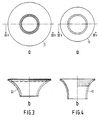
- Figs. 3 a and 3 b are a rear view and a longitudinal sectional view, respectively, through a yoke ring for a 110° (wide angle) deflection unit.
- Figs. 4 a and 4 b are a rear view and a longitudinal sectional view, respectively, through a yoke ring for a monochromatic d ata g raphic d isplay deflection unit.
- Fig. 1 is a diagrammatic longitudinal sectional view of a display tube 1 for monochrome or colour television. It consists of a cylindrical neck portion 2 and an adjoining flared portion 3 which is closed at the front (on the left on Fig. 1) by a display screen 4. Present in the neck portion 2 is shown diagrammatically an electrode system 5 with which one electron beam (in the case of a monochrome display tube) or three electron beams extending in one plane (in the case of colour television) can be generated.
- one electron beam in the case of a monochrome display tube
- three electron beams extending in one plane in the case of colour television
- a system of deflection coils 6 surrounding the tube 1 coaxially is provided on the tube 1 and consists of a first pair of (saddle-shaped) deflection coils 7, 7' for deflecting the electron beams in the horizontal direction, a second pair of (torroidal) deflection coils 8, 8' for deflecting the electron beams in the vertical direction and a yoke ring 9 supporting the pair of coils 8, 8'.
- the shape of the deflection coils 7, 7' and of the yoke ring 9 is adapted to the flared portion of the display tube 1.
- the horizontal deflection coils 7, 7' are situated on either side of a horizontal deflection plane, which plane coincides with the plane in which the three electron beams extend in the case of a colour TV tube.
- the vertical deflection coils 8, 8' are also situated on either side of said horizontal deflection plane.
- the vertical deflection plane is at right angles to said plane and hence coincides with the plane of the drawing.
- the yoke ring 9 is manufactured from sintered, oxydic ferromagnetic material. It has a flared shape so that it fits the deflection coil pair 7, 7' with a small amount of play.
- Fig. 2 a is a rear view and Fig, 2 b a longitudinal sectional view through a yoke ring for a deflection unit according to the invention.
- a yoke ring 10 which consists of two halves and has its largest outside diameter (on the cup side) of 86 mm and its smallest diameter (on the neck side) of 54 mm.
- the wall thickness of the yoke ring is 3 mm.
- the (90°) deflection unit for which it is destined is of the hybrid type, i.e. a toroidal field coil is wound on each yoke ring half. After the coil has been wound on each yoke ring half, the halves are secured together by means of a contact adhesive, for example cyanoacrylate.
- Fig. 3 a is a rear view and Fig. 3 b a longitudinal sectional view through a yoke ring for a deflection unit according to the invention.
- yoke ring 11 which is formed in one piece and has a largest outside diameter of 113 mm and a smallest outside diameter of 57.5 mm.
- the wall thickness of the yoke ring 11 is 4 mm.
- the (110°7) colour deflection unit for which it is destined is of the double-saddle type, i.e. both the line and the field deflection coil systems are of the saddle type and are together surrounded by the yoke ring.
- Fig. 4 a is a rear view and Fig. 4 b a longitudinal sectional view through a yoke ring for a deflection unit according to the invention.
- a yoke ring 12 which is formed in one piece and has an outside diameter of 54 mm at its widest end.
- the wall thickness of the yoke ring 12 is 3 mm; the thickness of a conventional yoke ring would be 6 mm. Due to its comparatively long cylindrical neck portion this is a product which is complicated to manufacture.
- the deflection unit for which the yoke ring 12, is destined, is a monochrome d ata g raphic d isplay unit.
- LiZn ferrite and NiZn ferrite examples of other materials which are suitable for the manufacture of thin-walled yoke rings.
- the invention also relates to deflection units for camera tubes.
- Fig. 5 shows diagrammatically a camera tube 13 which comprises a target 14 and external connection means 15.
- a deflection unit comprising a deflection coil system 16 is provided around the camera tube 13.
- a focusing coil 17 is also provided around the camera tube 13.
- TV cameras having a high number of lines for example, camera's for High-Definition TV (2000 lines) the system described gives great advantages.
- a mu-metal screening cylinder or a mu-metal roll is conventionally provided around the syste of coils of a camera tube so that on the one hand the deflection field is intensified and on the other hand a screening is formed against external interference fields ( inter alia the earth's magnetic field).
- the deflection fields are alternating fields so that especially the horizontal deflection fields with their rather high frequency are associated with interference eddy currents in the usual mu-metal screening due to the low resistivity of mu-metal. This is expressed by serious linearity errors and distortion of the deflection field. This is an undesired phenomenon in particular in the case of special camera tubes (so-called dissector tubes) for satellite navigation. For that use the deflection fields must be as linear as possible with the current.
- the magnetic induction in principle is the same function of the time as the current through the deflection coils. When a cylinder of an electrically conductive material is provided in said field, a resulting induction variation will arise which differs from the primary current
- a ferrite ring 18 for the field amplification, as is used also in deflection units for display tubes.
- a mu-metal screening 19 can be provided around said ferrite ring 18.
- ferrite ring 18 Since only a very restricted place is available for providing the ferrite ring 18, it is of importance for the invention to provide a thin-walled ferrite ring. Where a ferrite ring having a wall thickness of 6 mm cannot be used, a ferrite ring having a wall thickness of, for example, 2 mm can often be used indeed.
Landscapes
- Engineering & Computer Science (AREA)
- Chemical & Material Sciences (AREA)
- Ceramic Engineering (AREA)
- Manufacturing & Machinery (AREA)
- Materials Engineering (AREA)
- Structural Engineering (AREA)
- Organic Chemistry (AREA)
- Power Engineering (AREA)
- Formation Of Various Coating Films On Cathode Ray Tubes And Lamps (AREA)
- Vessels, Lead-In Wires, Accessory Apparatuses For Cathode-Ray Tubes (AREA)
Claims (13)
- Ablenkeinheit für eine Kathodenstrahlröhre mit einem ersten und einem zweiten Ablenkspulensystem und einem ringförmigen Kern aus einem gesinterten, oxidischen, ferromagnetischen Material, dadurch gekennzeichnet, daß der ringförmige Kern eine Wandstärke hat, die weniger als 6 mm beträgt, während der Sauerstoffgehalt des gesinterten, oxidischen, ferromagnetischen Materials des ringförmigen Kerns an oder in der Nähe der Oberfläche desselben dem Sauerstoffgehalt des ferromagnetischen Materials innerhalb des ringförmigen Kerns nahzu entspricht, wobei dieser Kern durch Sinterung in einer Atmosphäre mit einem während des ganzen Sinterungszyklus konstanten Sauerstoffgehalt und bei einer derartigen Temperatur hergestellt werden kann, daß beim Sintern die Differenz zwischen dem angelegten Sauerstoffdruck und dem Gleichgewichtswert des Teil-Sauerstoffdrucks des Ferrits bei der Sintertemperatur nicht größer ist als etwa 0,06 MPa.
- Ablenkeinheit für eine Kathodenstrahlröhre mit einem ersten und einem zweiten Ablenkspulensystem und mit einem ringförmigen Kern aus einem gesinterten, oxidischen, ferromagnetischen Material, dadurch gekennzeichnet, daß der ringförmige Kern eine Wandstärke von weniger als 6 mm hat, während der Sauerstoffgehalt des gesinterten, oxidischen, ferromagnetischen Materials des ringförmigen Kerns an oder in der Nähe der Oberfläche nahezu derselbe ist wie der Sauerstoffgehalt des ferromagnetischen Materials innerhalb des rinförmigen Kerns, wobei der genannte kern einen Sauerstoffgehalt hat, der im wesentlichen nicht stöchiometrisch ist.
- Ablenkeinheit nach Anspruch 1 oder 2, dadurch gekennzeichnet, daß der ringförmige Kern eine Wandstärke hat im Bereich von 2-4 mm.
- Ablenkeinheit für eine Kathodenstrahlröhre mit einem ersten und einem zweiten Ablenkspulensystem und einem ringförmigen Kern aus einem gesinterten, oxidischen, ferromagnetischen Material, dadurch gekennzeichnet, daß der ringförmige Kern eine Wandstärke von weniger als 6 mm hat, während der Sauerstoffgehalt des gesinterten, oxidischen, ferromagnetischen Materials des ringförmigen Kerns an oder in der Nähe der Oberfläche nahezu derselbe ist wie der Sauerstoffgehalt des ferromagnetischen Materials innerhalb des ringförmigen Kerns, und daß der ringförmige Kern aus zwei halbringförmigen Teilen besteht, die mit Hilfe eines Klebers miteinander verbunden sind.
- Ablenkeinheit nach Anspruch 4, dadurch gekennzeichnet, daß die Dicke der Klebeschicht höchstens 10 µm beträgt.
- Ablenkeinheit nach Anspruch 4 oder 5, dadurch gekennzeichnet, daß das der Kleber ein Kontaktkleber ist.
- Ablenkeinheit für eine Kathodenstrahlröhre mit einem ersten und einem zweiten Ablenkspulensystem und einem ringförmigen Kern aus einem gesinterten, oxidischen, ferromagnetischen Material, dadurch gekennzeichnet, daß der ringförmige Kern eine Wandstärke hat von weniger als 6 mm, während die Dicke einer Schicht auf der Oberfläche des ringförmigen Kerns, in der der Sauerstoffgehalt von dem Sauerstoffgehalt des restlichen Teils des ringförmigen Kerns wesentlich abweicht, so gering ist, daß der ringförmige Kern nahezu spannungsfrei ist.
- Ablenkeinheit nach Anspruch 7, dadurch gekennzeichnet, daß der ringförmige Kern aus Mn-Zn-Ferrit besteht und eine Dichte von mindestens 4,7 gcm‾³ aufweist.
- Ablenkeinheit nach Anspruch 7 oder 8, dadurch gekennzeichnet, daß der ringförmige Kern eine Wandstärke hat im Bereich von 2 bis 4 mm.
- Ablenkeinheit nach Anspruch 7, dadurch gekennzeichnet, daß der ringförmige Kern aus zwei halbringförmigen Teilen besteht, die mittels eines Klebers miteinander verbunden sind.
- Ablenkeinheit nach Anspruch 10, dadurch gekennzeichnet, daß die Dicke der Kleberschicht höchstens 10 µm beträgt.
- Ablenkeinheit nach Anspruch 10 oder 11, dadurch gekennzeichnet, daß der Kleber ein Kontaktkleber ist.
- Ringförmiger Kern zum Gebrauch in einer Ablenkeinheit nach einem der vorstehenden Ansprüche.
Applications Claiming Priority (4)
| Application Number | Priority Date | Filing Date | Title |
|---|---|---|---|
| NL8502155 | 1985-07-30 | ||
| NL8502155A NL8502155A (nl) | 1985-07-30 | 1985-07-30 | Afbuigeenheid voor beeldbuizen. |
| NL8600489 | 1986-02-27 | ||
| NL8600489A NL8600489A (nl) | 1986-02-27 | 1986-02-27 | Afbuigeenheid met dunwandige yokering voor kathodestraalbuizen. |
Publications (2)
| Publication Number | Publication Date |
|---|---|
| EP0210699A1 EP0210699A1 (de) | 1987-02-04 |
| EP0210699B1 true EP0210699B1 (de) | 1991-05-02 |
Family
ID=26646060
Family Applications (1)
| Application Number | Title | Priority Date | Filing Date |
|---|---|---|---|
| EP86201268A Expired - Lifetime EP0210699B1 (de) | 1985-07-30 | 1986-07-21 | Ablenkeinheit mit dünnwandigem Jochring für Kathodenstrahlröhre |
Country Status (5)
| Country | Link |
|---|---|
| US (1) | US4730145A (de) |
| EP (1) | EP0210699B1 (de) |
| JP (1) | JP2552535Y2 (de) |
| KR (1) | KR940006262B1 (de) |
| DE (1) | DE3679008D1 (de) |
Families Citing this family (5)
| Publication number | Priority date | Publication date | Assignee | Title |
|---|---|---|---|---|
| NL8800334A (nl) * | 1988-02-11 | 1989-09-01 | Philips Nv | Werkwijze voor het in tweeen delen van een voorwerp vervaardigd van een bros materiaal in het bijzonder een ringkern van ferromagnetisch materiaal voor een afbuigeenheid voor een beeldbuis en afbuigeenheid voor een beeldbuis voorzien van een ringkern gedeeld volgens zulk een werkwijze. |
| WO1996015543A1 (en) * | 1994-11-09 | 1996-05-23 | Philips Electronics N.V. | DEFLECTION RING OF SINTERED MgZn-FERRITE MATERIAL, CATHODE RAY TUBE COMPRISING SUCH A RING AND MOULDING MADE FROM THIS MATERIAL |
| WO1999003127A1 (en) * | 1997-07-09 | 1999-01-21 | Koninklijke Philips Electronics N.V. | Cathode ray tube having a deflection unit |
| CN1252790C (zh) * | 2002-11-19 | 2006-04-19 | Lg飞利浦显示器(韩国)株式会社 | 阴极射线管的偏转系统 |
| KR100489609B1 (ko) * | 2002-11-30 | 2005-05-17 | 엘지.필립스 디스플레이 주식회사 | 음극선관 |
Family Cites Families (10)
| Publication number | Priority date | Publication date | Assignee | Title |
|---|---|---|---|---|
| FR71999E (fr) * | 1957-05-10 | 1960-03-15 | Int Standard Electric Corp | Méthode de fabrication d'oxydes métalliques et de ferrites |
| DE1471428B2 (de) * | 1963-08-07 | 1970-10-08 | Siemens AG, 1000 Berlin u. 8000 München | Verfahren zur Herstellung von ferromagnetischen Mangan-Zink-Ferriten |
| FR1459875A (fr) * | 1965-08-11 | 1966-06-17 | Centre Nat Rech Scient | Perfectionnements apportés aux moyens pour ajuster à une valeur prédéterminée au cours d'un cycle thermique la teneur d'un corps en l'un de ses constituants volatils |
| ES342219A1 (es) * | 1966-07-06 | 1968-08-16 | Arco Societa Per L Ind Elettro | Procedimiento para la formacion de un yugo de deflexion pa-ra cinescopios. |
| US3948785A (en) * | 1971-01-04 | 1976-04-06 | Jean Berchtold | Process of manufacturing ferrite materials with improved magnetic and mechanical properties |
| US3989794A (en) * | 1971-01-07 | 1976-11-02 | Eastman Kodak Company | Process of manufacturing ferrite bodies of low porosity |
| JPS5027807A (de) * | 1973-07-12 | 1975-03-22 | ||
| NL7508146A (nl) * | 1975-07-09 | 1977-01-11 | Philips Nv | Afbuigspoelenstel met toroidaal gewikkelde spoe- len voor een kleurentelevisiebeeldbuis. |
| NL8004200A (nl) * | 1980-07-22 | 1982-02-16 | Philips Nv | Kunststofgebonden electromagnetische component en werkwijze voor het vervaardigen daarvan. |
| JPS5966845U (ja) * | 1982-10-27 | 1984-05-04 | 日本フエライト株式会社 | 偏向ヨ−クコア |
-
1986
- 1986-07-21 EP EP86201268A patent/EP0210699B1/de not_active Expired - Lifetime
- 1986-07-21 DE DE8686201268T patent/DE3679008D1/de not_active Expired - Lifetime
- 1986-07-25 US US06/890,765 patent/US4730145A/en not_active Expired - Lifetime
- 1986-07-30 KR KR1019860006244A patent/KR940006262B1/ko not_active Expired - Lifetime
-
1995
- 1995-07-17 JP JP1995007283U patent/JP2552535Y2/ja not_active Expired - Lifetime
Also Published As
| Publication number | Publication date |
|---|---|
| DE3679008D1 (de) | 1991-06-06 |
| EP0210699A1 (de) | 1987-02-04 |
| JP2552535Y2 (ja) | 1997-10-29 |
| JPH08194U (ja) | 1996-02-02 |
| US4730145A (en) | 1988-03-08 |
| KR940006262B1 (ko) | 1994-07-13 |
| KR870001639A (ko) | 1987-03-17 |
Similar Documents
| Publication | Publication Date | Title |
|---|---|---|
| EP0886297A3 (de) | Kathodenstrahlröhre | |
| US4242612A (en) | Deflection unit for color television display tubes | |
| US4730145A (en) | Deflection unit having a thin-walled yoke ring for cathode-ray tubes | |
| EP0989582A1 (de) | Kathodenstrahlröhre | |
| EP0244908B1 (de) | Verfahren zur Korrektur der dynamischen Konvergenzfehler und Farbbildröhre | |
| US4471261A (en) | Ferromagnetic yoke and a deflection unit for a television display tube | |
| EP0180947B1 (de) | Elektronenstrahlablenkjoch | |
| US2443032A (en) | Electromagnetic deflecting yoke and circuit | |
| JPS6229045A (ja) | 陰極線管の偏向ユニツト及びそこで使用する環状コア | |
| EP0313138B1 (de) | Elektronenstrahlröhre mit Ablenksystem | |
| NL8600489A (nl) | Afbuigeenheid met dunwandige yokering voor kathodestraalbuizen. | |
| US3075131A (en) | Deflection yoke core for cathode ray tubes | |
| JP2000106106A (ja) | 偏向ヨ―ク及びそれを用いた陰極線管装置並びにディスプレイ装置 | |
| US20030076058A1 (en) | Color cathode ray tube apparatus | |
| JPH0737525A (ja) | 偏向ヨーク | |
| JPS6251138A (ja) | カラ−受像管用偏向装置 | |
| US7157998B2 (en) | Ferrite core, deflection yoke, and color picture tube apparatus | |
| SU411544A1 (de) | ||
| JPS63254645A (ja) | カラー陰極線管 | |
| KR100313378B1 (ko) | 음극선관용 편향요크 코아 | |
| KR100295452B1 (ko) | 음극선관용 편향요크 | |
| JPH11176352A (ja) | 偏向ヨーク | |
| EP0977239A2 (de) | Ablenkjoch, dieses Ablenkjoch verwendende Kathodenstrahlröhre und Anzeigevorrichtung | |
| US20060273708A1 (en) | Display device comprising a deflection unit and a deflection unit for a display device | |
| JPH0521299B2 (de) |
Legal Events
| Date | Code | Title | Description |
|---|---|---|---|
| PUAI | Public reference made under article 153(3) epc to a published international application that has entered the european phase |
Free format text: ORIGINAL CODE: 0009012 |
|
| AK | Designated contracting states |
Kind code of ref document: A1 Designated state(s): DE FR GB IT NL |
|
| 17P | Request for examination filed |
Effective date: 19870702 |
|
| 17Q | First examination report despatched |
Effective date: 19880718 |
|
| GRAA | (expected) grant |
Free format text: ORIGINAL CODE: 0009210 |
|
| AK | Designated contracting states |
Kind code of ref document: B1 Designated state(s): DE FR GB IT NL |
|
| PG25 | Lapsed in a contracting state [announced via postgrant information from national office to epo] |
Ref country code: NL Effective date: 19910502 |
|
| REF | Corresponds to: |
Ref document number: 3679008 Country of ref document: DE Date of ref document: 19910606 |
|
| ITF | It: translation for a ep patent filed | ||
| ET | Fr: translation filed | ||
| NLV1 | Nl: lapsed or annulled due to failure to fulfill the requirements of art. 29p and 29m of the patents act | ||
| PLBE | No opposition filed within time limit |
Free format text: ORIGINAL CODE: 0009261 |
|
| STAA | Information on the status of an ep patent application or granted ep patent |
Free format text: STATUS: NO OPPOSITION FILED WITHIN TIME LIMIT |
|
| 26N | No opposition filed | ||
| ITPR | It: changes in ownership of a european patent |
Owner name: CAMBIO RAGIONE SOCIALE;PHILIPS ELECTRONICS N.V. |
|
| REG | Reference to a national code |
Ref country code: FR Ref legal event code: CD |
|
| REG | Reference to a national code |
Ref country code: FR Ref legal event code: CD |
|
| REG | Reference to a national code |
Ref country code: GB Ref legal event code: IF02 |
|
| REG | Reference to a national code |
Ref country code: FR Ref legal event code: D6 |
|
| REG | Reference to a national code |
Ref country code: GB Ref legal event code: 746 Effective date: 20021205 |
|
| PG25 | Lapsed in a contracting state [announced via postgrant information from national office to epo] |
Ref country code: IT Free format text: LAPSE BECAUSE OF NON-PAYMENT OF DUE FEES;WARNING: LAPSES OF ITALIAN PATENTS WITH EFFECTIVE DATE BEFORE 2007 MAY HAVE OCCURRED AT ANY TIME BEFORE 2007. THE CORRECT EFFECTIVE DATE MAY BE DIFFERENT FROM THE ONE RECORDED. Effective date: 20050721 |
|
| PGFP | Annual fee paid to national office [announced via postgrant information from national office to epo] |
Ref country code: GB Payment date: 20050727 Year of fee payment: 20 |
|
| PGFP | Annual fee paid to national office [announced via postgrant information from national office to epo] |
Ref country code: FR Payment date: 20050729 Year of fee payment: 20 |
|
| PGFP | Annual fee paid to national office [announced via postgrant information from national office to epo] |
Ref country code: DE Payment date: 20050913 Year of fee payment: 20 |
|
| PG25 | Lapsed in a contracting state [announced via postgrant information from national office to epo] |
Ref country code: GB Free format text: LAPSE BECAUSE OF EXPIRATION OF PROTECTION Effective date: 20060720 |
|
| REG | Reference to a national code |
Ref country code: GB Ref legal event code: PE20 |