EP0210714A2 - Teleskopische Verbindung - Google Patents
Teleskopische Verbindung Download PDFInfo
- Publication number
- EP0210714A2 EP0210714A2 EP86301980A EP86301980A EP0210714A2 EP 0210714 A2 EP0210714 A2 EP 0210714A2 EP 86301980 A EP86301980 A EP 86301980A EP 86301980 A EP86301980 A EP 86301980A EP 0210714 A2 EP0210714 A2 EP 0210714A2
- Authority
- EP
- European Patent Office
- Prior art keywords
- tubular member
- locking
- subsea
- metal
- pressure
- Prior art date
- Legal status (The legal status is an assumption and is not a legal conclusion. Google has not performed a legal analysis and makes no representation as to the accuracy of the status listed.)
- Granted
Links
Images
Classifications
-
- E—FIXED CONSTRUCTIONS
- E21—EARTH OR ROCK DRILLING; MINING
- E21B—EARTH OR ROCK DRILLING; OBTAINING OIL, GAS, WATER, SOLUBLE OR MELTABLE MATERIALS OR A SLURRY OF MINERALS FROM WELLS
- E21B43/00—Methods or apparatus for obtaining oil, gas, water, soluble or meltable materials or a slurry of minerals from wells
- E21B43/01—Methods or apparatus for obtaining oil, gas, water, soluble or meltable materials or a slurry of minerals from wells specially adapted for obtaining from underwater installations
- E21B43/0107—Connecting of flow lines to offshore structures
-
- E—FIXED CONSTRUCTIONS
- E21—EARTH OR ROCK DRILLING; MINING
- E21B—EARTH OR ROCK DRILLING; OBTAINING OIL, GAS, WATER, SOLUBLE OR MELTABLE MATERIALS OR A SLURRY OF MINERALS FROM WELLS
- E21B17/00—Drilling rods or pipes; Flexible drill strings; Kellies; Drill collars; Sucker rods; Cables; Casings; Tubings
- E21B17/02—Couplings; joints
-
- F—MECHANICAL ENGINEERING; LIGHTING; HEATING; WEAPONS; BLASTING
- F16—ENGINEERING ELEMENTS AND UNITS; GENERAL MEASURES FOR PRODUCING AND MAINTAINING EFFECTIVE FUNCTIONING OF MACHINES OR INSTALLATIONS; THERMAL INSULATION IN GENERAL
- F16L—PIPES; JOINTS OR FITTINGS FOR PIPES; SUPPORTS FOR PIPES, CABLES OR PROTECTIVE TUBING; MEANS FOR THERMAL INSULATION IN GENERAL
- F16L17/00—Joints with packing adapted to sealing by fluid pressure
- F16L17/10—Joints with packing adapted to sealing by fluid pressure the packing being sealed by the pressure of a fluid other than the fluid in or surrounding the pipe
-
- F—MECHANICAL ENGINEERING; LIGHTING; HEATING; WEAPONS; BLASTING
- F16—ENGINEERING ELEMENTS AND UNITS; GENERAL MEASURES FOR PRODUCING AND MAINTAINING EFFECTIVE FUNCTIONING OF MACHINES OR INSTALLATIONS; THERMAL INSULATION IN GENERAL
- F16L—PIPES; JOINTS OR FITTINGS FOR PIPES; SUPPORTS FOR PIPES, CABLES OR PROTECTIVE TUBING; MEANS FOR THERMAL INSULATION IN GENERAL
- F16L27/00—Adjustable joints; Joints allowing movement
- F16L27/12—Adjustable joints; Joints allowing movement allowing substantial longitudinal adjustment or movement
- F16L27/127—Adjustable joints; Joints allowing movement allowing substantial longitudinal adjustment or movement with means for locking the longitudinal adjustment or movement in the final mounted position
- F16L27/1275—Adjustable joints; Joints allowing movement allowing substantial longitudinal adjustment or movement with means for locking the longitudinal adjustment or movement in the final mounted position by means of at least an external threaded bolt
Definitions
- production from several subsea christmas trees flows through individual flowlines from each christmas tree to a central main gathering line on the ocean floor.
- the flowlines from these wells are also connected into the main gathering line.
- Making a connection between the flowlines and the main gathering line is often accomplished by using an articulated piping system having flexible ball and socket joints as shown in U.S. Patent Nos. 3,727,954 and 3,717,920 and remote collet type connectors as shown in U.S. Patent No. 3,096,999.
- Normally telescoping joints are provided with seals to contain the fluids within the interior of the joint from leaking to the exterior and to prevent entry of surrounding fluids into the joint.
- the length of flowline used to make such connection be adjustable so that even with multiple swivel joints there is not any stress introduced into the flowline or into the lines to which it is connected by having the connecting flowline too short, too long, or not properly aligned.
- U.S. Patent No. 4,341,484 discloses the use of hydraulic fluid injected between a drill string stabilizer and its supporting tapered pin to release frictional engagement between the stabilizer and the pin.
- the present invention relates to an improved subsea telescoping joint which includes a first tubular member having an external metal cylindrical sealing and locking surface, a second tubular member having an internal metal cylindrical sealing and locking surface, means for sealing between the end of each of said members to define a chamber between said members on the sides of sealing and locking surfaces, means for introducing fluid under pressure into said chamber to unlock the metal-to-metal sealing and locking engagement of such surfaces, said surfaces having a slight interference fit and surface finishes which ensure metal-to-metal sealing engagement when pressure from said chamber is released.
- An object of the present invention is to provide an improved subsea telescoping joint which both locks and seals with a metal-to-metal seal.
- a further object is to provide an improved subsea telescoping joint which provides a very substantial length adjustment for a flowline spool to be inserted between a flowline leading from an individual christmas tree to a main gathering system.
- Another object is to provide an improved subsea telescoping joint which is easily adjusted in length during subsea installation.
- Still another object of the present invention is to supply an interconnecting subsea piping system which is substantially shorter and more readily installed than the prior art articulated subsea piping system.
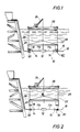
- flowline spool 10 having telescoping joint 12 in its midsection with flowline sections 11a and 11b extending outward from each end of joint 12, swivels 14 on each end and remote connectors 16 on each swivel 14 for connecting to subsea flowline 18 and riser 20.
- Spool 10 is connected to strongback 22 which is lowered to the subsea location by crane 24 from floating structure 26.
- Spool 10 is guided by connection to guidelines 28 which lead to the ends of flowline 18 and riser 20, both of which are provided with suitable ends 30 for connection by connectors 16 such as collet flanges when remote connectors are collet connectors.
- Spool 10 is lowered into position and telescoping joint 12 is adjusted as hereinafter described so that connectors 16 are in position to mate with ends 30.
- telescoping joint 12 is locked into position so that spool 10 is sealed and its length is fixed. Thereafter strongback 22 is disconnected from spool 10 and guidelines 28 are disconnected from flowline 18 and riser 20.
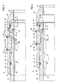
- Telescoping joint 12 shown in FIGURES 3 and 4 is the preferred form of joint of the present invention and includes inner tubular member 32 and outer tubular member 34.
- Inner tubular member 32 which is secured to flowline section 11b of spool 10 as by welding, includes sleeve 35 which is generally tubular in shape having central bore 36, exterior cylindrical surface 38 on its inner end and recessed cylindrical surface 40 located axially exterior from surface 38 and threaded reduced diameter 43.
- Hub 41 threadedly engages diameter 43 and is sealed thereto by seal 45.
- Hub 41 includes exterior diametrical surface 39, which is essentially the same radial extent as surface 38, so that recess 40 is located between surfaces 38 and 40.
- Hub 41 also includes spanner wrench holes 47, whereby a spanner wrench (not shown) may be used to threadedly engage hub 41 to diameter 43.
- the central portion of recess 40 includes sealing and locking surface 42 which has a surface finish to provide metal-to-metal sealing which is not a smooth finish but rather a lightly serrated finish.
- Grooves 44 and 46 in surfaces 38 and 39 include seal rings 48.
- Outer tubular member 34 includes hub 50 which is suitable connected to flowline section 11a of spool 10 as by welding, and sleeve 52 which is connected and sealed to hub 50.
- the interior of sleeve 52 includes bore 54 at one end and bore 56 at its other end and inward projection 58 therebetween.
- the end of sleeve 52 with bore 54 has threaded surface 51 located exterior of bore 54.
- Hub 50 also includes threaded surface 53 for engaging surface 51 of sleeve 52 and seal 55 for sealing therebetween.
- Hub 50 includes bore 57 which is essentially the same diameter as bore 54 of sleeve 52 and forms an extension thereof.
- Projection 58 has inner sealing and locking surface 60 which has a surface finish to provide metal-to-metal sealing. Such surface is not a smooth finish but rather a lightly serrated finish similar to the finish on surface 42. The diameters of surfaces 42 and 60 have a slight interference fit so that they are not movable with respect to each other.
- Ports 62 and 64 extend through sleeve 52 at each side of projection 58 as shown and are provided with suitable fittings 66 to which lines 68 are connected for supplying fluid under pressure to the interior of sleeve 52.
- Seal rings 48 seal against the surfaces of bores 54, 56 and 57. Since they seal against surfaces having the same diameter, the joint is effectively balanced, that is, it does not have any extending or retracting net forces developing as a result of pressure supplied to the interior of the sleeve 52.
- joint 12 is locked and sealed. To release joint 12 from the locked position it is only necessary to supply fluid under pressure through hoses 68 to ports 62 and 64. When sufficient pressure is introduced into chambers 70 and 72 between members 32 and 34 and opposite sides of projection 58, the diameters thereof changes sufficiently so that there is no longer an interference fit but rather a slight clearance. With pressure in chambers 70 and 72 members 32 and 34 are movable with respect to each other so that joint 12 can be moved from a contracted position shown in FIGURE 3 to the extended position shown in FIGURE 4. Joint 12 is locked in position by relieving the fluid pressure from chambers 70 and 72.
- ports 62 and 64 may be used to test the effectiveness of the metal-to-metal seal between surfaces 42 and 60. This may be accomplished by relieving pressure from one of ports 62 and 64 and thereafter supplying fluid pressure to the other of such ports with suitable means, such as a pressure gauge connected to the relieved port, to provide an indication of the pressure in the relieved port.
- suitable means such as a pressure gauge connected to the relieved port
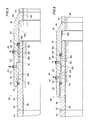
- Telescoping joint 80 is a modified form of the present invention and includes inner tubular member 82 which is secured to flowline section 11b of the flowline spool 10 and outer tubular member 84 which is secured to flowline section 11a of the spool 10.
- Inner tubular member 82 includes central bore 86, exterior surface 88, groove 90 at the end of surface 88, serrated sealing and locking surface 92 which has a smaller diameter than surface 88 and exterior end sealing surface 94 which has a smaller diameter than surface 92.
- Outer tubular member 84 includes hub portion 96 having central bore 98 on the end connecting to flowline section 11b and sleeve portion 97 with bore 100. Groove 102 is near the end of bore 100 as shown.
- Surface 104 has a larger diameter than bore 100.
- Serrated metal-to-metal sealing and locking surface 106 is on the interior of sleeve portion 97 and has a diameter slightly smaller than the diameter of surface 92 of inner tubular member 82 so that there is a slight interference fit between the two sealing and locking surfaces 92 and 106.
- Tubular member 84 has bore 108 which is on its end that is opposite to the hub portion 96 and is larger in diameter than the exterior surface 88 of member 82.
- Seal ring 110 is positioned in groove 90 and seals against the surface of bore 108.
- Sleeve portion 97 includes groove 102 with seal ring 112 positioned therein which seals against surface 94 of inner tubular member 82.
- Ports 114 and 116 extend through outer tubular member 84 to communicate with chamber 118, between surfaces 92 and 108, and chamber 120, between surfaces 94 and 106, at opposite sides of surface 106.
- Suitable fittings 122 are connected into bores 114 and 116 and lines 124 connect to fittings 122 to supply fluid under pressure to the interior of outer tubular member 84.
- joint 80 is similar to the operation of joint 12 in that the introduction of fluid under pressure into chambers 118 and 120 between the inner and outer tubular members 82 and 84 causes an unlocking of the engagement of the surfaces 92 and 106 so that joint 80 may be extended to the position shown in FIGURE 5 or retracted to the position shown in FIGURE 6.
- the pressure is relieved from chambers 118 and 120.
- the relief of pressure in chambers 118 and 120 causes surfaces 92 and 106 to engage in locking and metal-to-metal sealing contact. This not only locks joint 80 in the desired position but also provides a metal-to-metal seal between inner and outer tubular members 82 and 84.
- Ports 114 and 116 can also be used to test the effectiveness of the metal-to-metal seal of surfaces 92 and 106 by supplying less than unlocking pressure to one port and sensing, at the other port, any pressure leakage into the other chamber.
- seals 110 and 112 are such that there is an effective pressure force created when fluid pressure is supplied to chambers 118 and 120 which force tends to move joint members 82 and 84 to their extended position. This pressure assist in extension is expected to be helpful to divers attempting to make the final connection of flowline spool 10 in place between subsea flowline 18 and riser 20.
Landscapes
- Engineering & Computer Science (AREA)
- General Engineering & Computer Science (AREA)
- Mining & Mineral Resources (AREA)
- Life Sciences & Earth Sciences (AREA)
- Geology (AREA)
- Mechanical Engineering (AREA)
- Physics & Mathematics (AREA)
- Fluid Mechanics (AREA)
- Geochemistry & Mineralogy (AREA)
- Environmental & Geological Engineering (AREA)
- General Life Sciences & Earth Sciences (AREA)
- Quick-Acting Or Multi-Walled Pipe Joints (AREA)
- Joints Allowing Movement (AREA)
- Cable Accessories (AREA)
- Separation By Low-Temperature Treatments (AREA)
- Connector Housings Or Holding Contact Members (AREA)
- Organic Low-Molecular-Weight Compounds And Preparation Thereof (AREA)
- Saccharide Compounds (AREA)
- Cephalosporin Compounds (AREA)
- Mechanical Coupling Of Light Guides (AREA)
- Manufacture, Treatment Of Glass Fibers (AREA)
- Investigation Of Foundation Soil And Reinforcement Of Foundation Soil By Compacting Or Drainage (AREA)
- Non-Disconnectible Joints And Screw-Threaded Joints (AREA)
Priority Applications (1)
| Application Number | Priority Date | Filing Date | Title |
|---|---|---|---|
| AT86301980T ATE57428T1 (de) | 1985-08-02 | 1986-03-18 | Teleskopische verbindung. |
Applications Claiming Priority (2)
| Application Number | Priority Date | Filing Date | Title |
|---|---|---|---|
| US06/761,692 US4720124A (en) | 1985-08-02 | 1985-08-02 | Telescoping joint |
| US761692 | 1985-08-02 |
Publications (3)
| Publication Number | Publication Date |
|---|---|
| EP0210714A2 true EP0210714A2 (de) | 1987-02-04 |
| EP0210714A3 EP0210714A3 (en) | 1987-06-16 |
| EP0210714B1 EP0210714B1 (de) | 1990-10-10 |
Family
ID=25062987
Family Applications (1)
| Application Number | Title | Priority Date | Filing Date |
|---|---|---|---|
| EP86301980A Expired - Lifetime EP0210714B1 (de) | 1985-08-02 | 1986-03-18 | Teleskopische Verbindung |
Country Status (11)
| Country | Link |
|---|---|
| US (1) | US4720124A (de) |
| EP (1) | EP0210714B1 (de) |
| JP (1) | JPH0631665B2 (de) |
| KR (1) | KR870002350A (de) |
| AT (1) | ATE57428T1 (de) |
| AU (1) | AU575470B2 (de) |
| BR (1) | BR8602679A (de) |
| CA (1) | CA1253436A (de) |
| DE (1) | DE3674849D1 (de) |
| NO (1) | NO863122L (de) |
| SG (1) | SG79391G (de) |
Cited By (8)
| Publication number | Priority date | Publication date | Assignee | Title |
|---|---|---|---|---|
| EP0272771A1 (de) * | 1986-12-24 | 1988-06-29 | Cooper Industries, Inc. | Teleskop-Verbindung |
| AU575470B2 (en) * | 1985-08-02 | 1988-07-28 | Cooper Cameron Corporation | Telescoping subsea flowline connection |
| WO1989003956A1 (en) * | 1987-10-27 | 1989-05-05 | Rintuv Hb | Tube joint |
| GB2180312B (en) * | 1985-07-31 | 1989-09-13 | Pond Ltd R J | Pipe connection joints |
| EP0522934A1 (de) * | 1991-07-12 | 1993-01-13 | Gaz De France (Service National) | Sattelrohrverbindung und eine Einheit bestehend aus dem Sattelstück und dem Rohr |
| EP0564223A1 (de) * | 1992-03-31 | 1993-10-06 | Cooper Cameron Corporation | Sicherheitsverbindung für eine Flüssigkeitsleitung |
| GB2322175A (en) * | 1997-02-12 | 1998-08-19 | Dril Quip Inc | Telescopic joint between conduits of two riser connectors. |
| GB2554890A (en) * | 2016-10-12 | 2018-04-18 | Poulton Tech Limited | A seal assembly |
Families Citing this family (18)
| Publication number | Priority date | Publication date | Assignee | Title |
|---|---|---|---|---|
| DE3813574C1 (de) * | 1988-04-22 | 1989-08-24 | Effem Gmbh, 2810 Verden, De | |
| US4887846A (en) * | 1988-04-22 | 1989-12-19 | Cameron Iron Works Usa, Inc. | Subsea tubular joint |
| US5098132A (en) * | 1990-06-12 | 1992-03-24 | Cooper Industries, Inc. | Length compensating joint |
| US6044904A (en) * | 1997-12-18 | 2000-04-04 | Csr Polypipe, Inc. | Wellhead assembly |
| US6056324A (en) * | 1998-05-12 | 2000-05-02 | Dril-Quip, Inc. | Threaded connector |
| US6203105B1 (en) | 1999-08-20 | 2001-03-20 | Mccord Winn Textron Inc. | Vehicle impact responsive multiple bladder seating and headrest system and method |
| WO2005099059A2 (en) * | 2004-04-05 | 2005-10-20 | Rizzuto Salvatore A Jr | Slip-joint connection for electric service conduit to service boxes |
| US7503395B2 (en) * | 2005-05-21 | 2009-03-17 | Schlumberger Technology Corporation | Downhole connection system |
| US8752635B2 (en) * | 2006-07-28 | 2014-06-17 | Schlumberger Technology Corporation | Downhole wet mate connection |
| US7798213B2 (en) * | 2006-12-14 | 2010-09-21 | Baker Hughes Incorporated | Radial spring latch apparatus and methods for making and using same |
| US20090026765A1 (en) * | 2007-07-24 | 2009-01-29 | Oceaneering International, Inc. | Connector Jumper |
| US7730957B2 (en) * | 2007-08-01 | 2010-06-08 | Halliburton Energy Services, Inc. | Well tool with line and installation method |
| DE102012110167B4 (de) * | 2012-10-24 | 2014-06-18 | Sick Ag | Sensor |
| US10240700B2 (en) | 2013-02-22 | 2019-03-26 | Mitsubishi Heavy Industries Compressor Corporation | Expansion joint and compression system |
| US9441426B2 (en) | 2013-05-24 | 2016-09-13 | Oil States Industries, Inc. | Elastomeric sleeve-enabled telescopic joint for a marine drilling riser |
| IT201600081363A1 (it) | 2016-08-02 | 2018-02-02 | Saipem Spa | Sistema e metodo di connessione per connettere due condotti in un corpo d'acqua |
| EP4463611A4 (de) | 2022-04-27 | 2026-01-14 | Sri Energy Inc | Schiebeverbinderspule |
| US20250223890A1 (en) * | 2024-01-09 | 2025-07-10 | Fmc Technologies, Inc. | Subsea expansion joint |
Family Cites Families (23)
| Publication number | Priority date | Publication date | Assignee | Title |
|---|---|---|---|---|
| FR1141071A (fr) * | 1956-01-12 | 1957-08-26 | S N Marep | Procédé pour l'assemblage par frettage de raccords filetés |
| US2992479A (en) * | 1958-05-14 | 1961-07-18 | Musser C Walton | Method of making equal temperature press-fit of tubular members |
| US3096999A (en) * | 1958-07-07 | 1963-07-09 | Cameron Iron Works Inc | Pipe joint having remote control coupling means |
| US3114566A (en) * | 1961-04-21 | 1963-12-17 | Kobe Inc | Shrink fit tubing joint |
| US3494642A (en) * | 1968-01-10 | 1970-02-10 | Kobe Inc | Friction-type joint with different moduli of elasticity |
| US3717920A (en) * | 1971-03-25 | 1973-02-27 | Cameron Iron Works Inc | Apparatus for making an underwater pipeline connection |
| US4011918A (en) * | 1976-01-21 | 1977-03-15 | Christensen, Inc. | Stabilizer for drill strings |
| US4195865A (en) * | 1976-11-03 | 1980-04-01 | Martin Charles F | Apparatus for connecting tubular members |
| US4371198A (en) * | 1976-11-03 | 1983-02-01 | Martin Charles F | Apparatus for connecting tubular members |
| US4138147A (en) * | 1976-12-27 | 1979-02-06 | Manchester Luther L | Coupling device |
| GB2033518B (en) * | 1978-11-10 | 1983-01-26 | Hunting Oilfield Services Ltd | Pipe connectors |
| US4298221A (en) * | 1977-01-26 | 1981-11-03 | Hunting Oilfield Services (U.K.) Limited | Pipe connectors |
| US4109945A (en) * | 1977-02-07 | 1978-08-29 | Manchester Luther L | Apparatus for connecting together flowline end portions |
| US4124230A (en) * | 1977-05-04 | 1978-11-07 | Vetco, Inc. | Rigid pipe connector with locking screws and method of making the same |
| US4124232A (en) * | 1977-05-04 | 1978-11-07 | Vetco, Inc. | Rigid pipe connector with lock elements and method of making the same |
| JPS5428932A (en) * | 1977-08-05 | 1979-03-03 | Kouji Kawai | Device of increasing compression pressure in case of direct airrcooling of combustion chamber and travelling at fixed speed of automobile engine |
| SE7907277L (sv) * | 1979-08-31 | 1981-03-01 | Ffv Industriprodukter Ab | Friktionsforband |
| GB2064041B (en) * | 1979-11-19 | 1983-07-27 | Hunting Oilfield Services Ltd | Pipe connectors |
| US4436325A (en) * | 1980-12-08 | 1984-03-13 | Big Inch Marine Systems, Inc. | Coupling |
| US4648627A (en) * | 1984-01-18 | 1987-03-10 | Dril-Quip, Inc. | Stabbing connector |
| US4600062A (en) * | 1984-07-13 | 1986-07-15 | 501 Dailey Petroleum Services Corporation | Shock absorbing drilling tool |
| US4720124A (en) * | 1985-08-02 | 1988-01-19 | Cameron Iron Works, Inc. | Telescoping joint |
| KR100854328B1 (ko) | 2006-07-07 | 2008-08-28 | 엘지전자 주식회사 | 발광 소자 패키지 및 그 제조방법 |
-
1985
- 1985-08-02 US US06/761,692 patent/US4720124A/en not_active Expired - Lifetime
-
1986
- 1986-03-18 DE DE8686301980T patent/DE3674849D1/de not_active Expired - Lifetime
- 1986-03-18 EP EP86301980A patent/EP0210714B1/de not_active Expired - Lifetime
- 1986-03-18 AT AT86301980T patent/ATE57428T1/de not_active IP Right Cessation
- 1986-03-20 AU AU54926/86A patent/AU575470B2/en not_active Ceased
- 1986-03-24 CA CA000504857A patent/CA1253436A/en not_active Expired
- 1986-04-30 KR KR1019860003360A patent/KR870002350A/ko not_active Withdrawn
- 1986-05-14 JP JP61110460A patent/JPH0631665B2/ja not_active Expired - Lifetime
- 1986-06-10 BR BR8602679A patent/BR8602679A/pt not_active IP Right Cessation
- 1986-08-01 NO NO863122A patent/NO863122L/no unknown
-
1991
- 1991-09-26 SG SG793/91A patent/SG79391G/en unknown
Cited By (13)
| Publication number | Priority date | Publication date | Assignee | Title |
|---|---|---|---|---|
| GB2180312B (en) * | 1985-07-31 | 1989-09-13 | Pond Ltd R J | Pipe connection joints |
| AU575470B2 (en) * | 1985-08-02 | 1988-07-28 | Cooper Cameron Corporation | Telescoping subsea flowline connection |
| EP0272771A1 (de) * | 1986-12-24 | 1988-06-29 | Cooper Industries, Inc. | Teleskop-Verbindung |
| WO1989003956A1 (en) * | 1987-10-27 | 1989-05-05 | Rintuv Hb | Tube joint |
| EP0522934A1 (de) * | 1991-07-12 | 1993-01-13 | Gaz De France (Service National) | Sattelrohrverbindung und eine Einheit bestehend aus dem Sattelstück und dem Rohr |
| FR2679002A1 (fr) * | 1991-07-12 | 1993-01-15 | Gaz De France | Selle de raccordement a une canalisation et ensemble forme par cette selle et la canalisation. |
| EP0564223A1 (de) * | 1992-03-31 | 1993-10-06 | Cooper Cameron Corporation | Sicherheitsverbindung für eine Flüssigkeitsleitung |
| GB2322175A (en) * | 1997-02-12 | 1998-08-19 | Dril Quip Inc | Telescopic joint between conduits of two riser connectors. |
| US5992893A (en) * | 1997-02-12 | 1999-11-30 | Drill-Quip, Inc. | Connector |
| GB2322175B (en) * | 1997-02-12 | 2001-01-10 | Dril Quip Inc | Connector |
| GB2554890A (en) * | 2016-10-12 | 2018-04-18 | Poulton Tech Limited | A seal assembly |
| GB2554890B (en) * | 2016-10-12 | 2019-01-02 | Poulton Tech Limited | A seal assembly |
| US11193610B2 (en) | 2016-10-12 | 2021-12-07 | Poulton Technologies Limited | Seal assembly |
Also Published As
| Publication number | Publication date |
|---|---|
| CA1253436A (en) | 1989-05-02 |
| JPH0631665B2 (ja) | 1994-04-27 |
| BR8602679A (pt) | 1987-03-17 |
| EP0210714A3 (en) | 1987-06-16 |
| EP0210714B1 (de) | 1990-10-10 |
| KR870002350A (ko) | 1987-03-30 |
| NO863122D0 (no) | 1986-08-01 |
| JPS6235194A (ja) | 1987-02-16 |
| NO863122L (no) | 1987-02-03 |
| ATE57428T1 (de) | 1990-10-15 |
| SG79391G (en) | 1991-11-15 |
| AU575470B2 (en) | 1988-07-28 |
| DE3674849D1 (de) | 1990-11-15 |
| AU5492686A (en) | 1987-02-05 |
| US4720124A (en) | 1988-01-19 |
Similar Documents
| Publication | Publication Date | Title |
|---|---|---|
| US4720124A (en) | Telescoping joint | |
| US5044672A (en) | Metal-to-metal sealing pipe swivel joint | |
| US6554324B1 (en) | Apparatus and method for connecting tubular members | |
| CA1086223A (en) | Split-ring riser latch | |
| US4629224A (en) | Tubular connection | |
| US3455578A (en) | Fluid pressure releasable automatic tool joint | |
| US3450421A (en) | Ball connector | |
| EP0306127B1 (de) | Abdichtanordnung für unterseeischen Futterrohraufhänger | |
| US4374595A (en) | Metal to metal sealed joint for tubing string | |
| US4693498A (en) | Anti-rotation tubular connection for flowlines or the like | |
| US5423575A (en) | Concentric riser joint with self-aligning coupling | |
| US4863314A (en) | Hydraulic stab connector, frictionless | |
| US6173781B1 (en) | Slip joint intervention riser with pressure seals and method of using the same | |
| US3732923A (en) | Remote underwater flowline connection | |
| OA10248A (en) | Multiple-seal underwater pipe-riser connector | |
| US4522430A (en) | Quick connect coupler | |
| EP2802731B1 (de) | Dichtungsanordnung für verschachtelte doppelbohrungsrohre | |
| US6032736A (en) | Multi-gage blowout preventer test tool and method | |
| CA1084899A (en) | Swivel connector | |
| US5314024A (en) | Angular and radial self-aligning coupling | |
| JP2000510208A (ja) | 滑り継手 | |
| GB2356210A (en) | Seal member for a wellhead assembly | |
| GB2085063A (en) | Devices for connecting strings of pipes to underwater installations | |
| US4451056A (en) | Remotely operated underwater tension connector | |
| CA1127963A (en) | Vertically moored platform casing tieback |
Legal Events
| Date | Code | Title | Description |
|---|---|---|---|
| PUAI | Public reference made under article 153(3) epc to a published international application that has entered the european phase |
Free format text: ORIGINAL CODE: 0009012 |
|
| AK | Designated contracting states |
Kind code of ref document: A2 Designated state(s): AT BE CH DE FR GB IT LI LU NL SE |
|
| PUAL | Search report despatched |
Free format text: ORIGINAL CODE: 0009013 |
|
| AK | Designated contracting states |
Kind code of ref document: A3 Designated state(s): AT BE CH DE FR GB IT LI LU NL SE |
|
| 17P | Request for examination filed |
Effective date: 19871118 |
|
| 17Q | First examination report despatched |
Effective date: 19880701 |
|
| GRAA | (expected) grant |
Free format text: ORIGINAL CODE: 0009210 |
|
| AK | Designated contracting states |
Kind code of ref document: B1 Designated state(s): AT BE CH DE FR GB IT LI LU NL SE |
|
| PG25 | Lapsed in a contracting state [announced via postgrant information from national office to epo] |
Ref country code: SE Effective date: 19901010 Ref country code: LI Effective date: 19901010 Ref country code: CH Effective date: 19901010 Ref country code: BE Effective date: 19901010 Ref country code: AT Effective date: 19901010 |
|
| REF | Corresponds to: |
Ref document number: 57428 Country of ref document: AT Date of ref document: 19901015 Kind code of ref document: T |
|
| REF | Corresponds to: |
Ref document number: 3674849 Country of ref document: DE Date of ref document: 19901115 |
|
| ITF | It: translation for a ep patent filed | ||
| ET | Fr: translation filed | ||
| REG | Reference to a national code |
Ref country code: CH Ref legal event code: PL |
|
| RAP2 | Party data changed (patent owner data changed or rights of a patent transferred) |
Owner name: COOPER INDUSTRIES,INC. |
|
| NLXE | Nl: other communications concerning ep-patents (part 3 heading xe) |
Free format text: IN PAT.BUL.24/90,PAGES 3411 AND 3437:CORR.:COOPER INDUSTRIES, INC. |
|
| RAP2 | Party data changed (patent owner data changed or rights of a patent transferred) |
Owner name: COOPER INDUSTRIES INC. |
|
| PG25 | Lapsed in a contracting state [announced via postgrant information from national office to epo] |
Ref country code: LU Free format text: LAPSE BECAUSE OF NON-PAYMENT OF DUE FEES Effective date: 19910331 |
|
| NLT2 | Nl: modifications (of names), taken from the european patent patent bulletin |
Owner name: COOPER INDUSTRIES, INC. TE CLEVELAND, OHIO, VER. S |
|
| NLT2 | Nl: modifications (of names), taken from the european patent patent bulletin |
Owner name: COOPER INDUSTRIES, INC. TE HOUSTON, TEXAS, VER. ST |
|
| ITPR | It: changes in ownership of a european patent |
Owner name: CESSIONE;COOPER INDUSTRIES INC. |
|
| PLBE | No opposition filed within time limit |
Free format text: ORIGINAL CODE: 0009261 |
|
| STAA | Information on the status of an ep patent application or granted ep patent |
Free format text: STATUS: NO OPPOSITION FILED WITHIN TIME LIMIT |
|
| 26N | No opposition filed | ||
| BECN | Be: change of holder's name |
Effective date: 19910206 |
|
| ITTA | It: last paid annual fee | ||
| PGFP | Annual fee paid to national office [announced via postgrant information from national office to epo] |
Ref country code: GB Payment date: 19950208 Year of fee payment: 10 |
|
| PGFP | Annual fee paid to national office [announced via postgrant information from national office to epo] |
Ref country code: FR Payment date: 19950315 Year of fee payment: 10 |
|
| PGFP | Annual fee paid to national office [announced via postgrant information from national office to epo] |
Ref country code: DE Payment date: 19950328 Year of fee payment: 10 |
|
| PGFP | Annual fee paid to national office [announced via postgrant information from national office to epo] |
Ref country code: NL Payment date: 19950331 Year of fee payment: 10 |
|
| REG | Reference to a national code |
Ref country code: GB Ref legal event code: 732E |
|
| PG25 | Lapsed in a contracting state [announced via postgrant information from national office to epo] |
Ref country code: GB Effective date: 19960318 |
|
| PG25 | Lapsed in a contracting state [announced via postgrant information from national office to epo] |
Ref country code: NL Effective date: 19961001 |
|
| GBPC | Gb: european patent ceased through non-payment of renewal fee |
Effective date: 19960318 |
|
| PG25 | Lapsed in a contracting state [announced via postgrant information from national office to epo] |
Ref country code: FR Effective date: 19961129 |
|
| NLV4 | Nl: lapsed or anulled due to non-payment of the annual fee |
Effective date: 19961001 |
|
| PG25 | Lapsed in a contracting state [announced via postgrant information from national office to epo] |
Ref country code: DE Effective date: 19961203 |
|
| REG | Reference to a national code |
Ref country code: FR Ref legal event code: ST |
|
| PG25 | Lapsed in a contracting state [announced via postgrant information from national office to epo] |
Ref country code: IT Free format text: LAPSE BECAUSE OF NON-PAYMENT OF DUE FEES;WARNING: LAPSES OF ITALIAN PATENTS WITH EFFECTIVE DATE BEFORE 2007 MAY HAVE OCCURRED AT ANY TIME BEFORE 2007. THE CORRECT EFFECTIVE DATE MAY BE DIFFERENT FROM THE ONE RECORDED. Effective date: 20050318 |