EP0210844A2 - Spleissen und Laden von Band in Kassetten - Google Patents
Spleissen und Laden von Band in Kassetten Download PDFInfo
- Publication number
- EP0210844A2 EP0210844A2 EP86305711A EP86305711A EP0210844A2 EP 0210844 A2 EP0210844 A2 EP 0210844A2 EP 86305711 A EP86305711 A EP 86305711A EP 86305711 A EP86305711 A EP 86305711A EP 0210844 A2 EP0210844 A2 EP 0210844A2
- Authority
- EP
- European Patent Office
- Prior art keywords
- tape
- cassette
- splicing
- leader
- splicing surface
- Prior art date
- Legal status (The legal status is an assumption and is not a legal conclusion. Google has not performed a legal analysis and makes no representation as to the accuracy of the status listed.)
- Granted
Links
Images


Classifications
-
- G—PHYSICS
- G11—INFORMATION STORAGE
- G11B—INFORMATION STORAGE BASED ON RELATIVE MOVEMENT BETWEEN RECORD CARRIER AND TRANSDUCER
- G11B23/00—Record carriers not specific to the method of recording or reproducing; Accessories, e.g. containers, specially adapted for co-operation with the recording or reproducing apparatus ; Intermediate mediums; Apparatus or processes specially adapted for their manufacture
- G11B23/02—Containers; Storing means both adapted to cooperate with the recording or reproducing means
- G11B23/113—Apparatus or processes specially adapted for the manufacture of magazines or cassettes, e.g. initial loading into container
-
- G—PHYSICS
- G11—INFORMATION STORAGE
- G11B—INFORMATION STORAGE BASED ON RELATIVE MOVEMENT BETWEEN RECORD CARRIER AND TRANSDUCER
- G11B23/00—Record carriers not specific to the method of recording or reproducing; Accessories, e.g. containers, specially adapted for co-operation with the recording or reproducing apparatus ; Intermediate mediums; Apparatus or processes specially adapted for their manufacture
- G11B23/20—Record carriers not specific to the method of recording or reproducing; Accessories, e.g. containers, specially adapted for co-operation with the recording or reproducing apparatus ; Intermediate mediums; Apparatus or processes specially adapted for their manufacture with provision for splicing to provide permanent or temporary connections
- G11B23/26—Record carriers not specific to the method of recording or reproducing; Accessories, e.g. containers, specially adapted for co-operation with the recording or reproducing apparatus ; Intermediate mediums; Apparatus or processes specially adapted for their manufacture with provision for splicing to provide permanent or temporary connections of leaders for loading or threading, e.g. to form a temporary connection
Definitions
- the invention relates to an apparatus and method for splicing and loading of tape into cassettes.
- Magnetic tape cassettes (eg audio and video tape cassettes) are supplied commercially either as blank tape or as pre-recorded tape.
- the cassette comprises two rotatable hubs, two lengths of leader tape one secured to each hub and a predetermined length of magnetic tape having its ends spliced to the two leaders.
- magnetic tape is loaded to a V-zero cassette, ie a cassette containing a relatively short length of leader secured by one end to one hub and by the other end to the other hub.
- the first step in loading is to cut the leader into two separate leader lengths.
- the magnetic tape to be loaded is then spliced to one length of leader and. the hub to which that leader length is connected is rotated to wind a predetermined length of magnetic tape onto the same hub.
- the magnetic tape is then cut and its trailing end spliced to the leading end of the remaining leader length so that the two hubs are connected by a leader-magnetic-leader continuous tape sequence.
- This apparatus comprises means for holding a supply reel of magnetic tape, means for supporting a tape cassette (eg by its hubs), a splicing assembly comprising a stationary splicing head and first and second movable splicing heads which are alternately moveable into contiguous relation with the stationary splicing head, means for releasably holding tape ends on the stationary and moveable splicing heads, means for slitting tape supported by the splicing assembly, means for rotating the supply reel and one of the cassette hubs to cause magnetic tape spliced to a leader on the hub to be unwound from the supply reel and wound on the hub in question, and means for applying splicing tape to the abutting ends of leader and magnetic tapes supported by the splicing assembly.
- cassette loading commences with the leader ends (ie a cut hub-hub leader length) held on the contiguously disposed stationary head and first splicing head, respectively, and the end of the magnetic tape held on the second splicing head.
- the first moveable splicing head is then moved away from the stationary splicing head and the second moveable head with its held end of the magnetic tape is m.oved.,into contiguous relation with the stationary head. This brings the leader held on the stationary head into end-to-end abutment with the magnetic tape and the two are then spliced together.
- the spliced leader-magnetic tape is then wound onto the cassette hub to which the leader is secured and winding continued until a predetermined length of magnetic tape has been loaded onto the hub.
- the magnetic tape is then slit.
- the second moveable splicing head which continues to hold the leading edge of the magnetic tape supply, is then moved away from the stationary head leaving a trailing end of magnetic tape from the newly loaded cassette held by the stationary head. Moving the first moveable splicing head back into contiguous relation with respect to the stationary head juxtaposes the leading end of the remaining cut leader length in abutment to the trailing end of magnetic tape held on the stationary head. These two ends are then spliced to complete the production of a loaded cassette.
- the apparatus described in US Patent 3637153 includes control means for selectively operating the components of the apparatus to perform the above-described operations in the sequence given.
- a method of loading a cassette with use tape comprises disposing an end of a terminal portion of a use tape upon a splicing surface; releasably retaining said end in such disposition; extracting leader tape from a leadered cassette supported so that its hubs may ..
- the end of the terminal portion of the use tape is releasably retained on the splicing surface by applying a vacuum through perforations in said surface.
- leader extraction is effected by operation of leader extraction means comprising a first member for engaging the first leader tape portion and bringing said first portion into contact with said splicing surface and a second member for engaging the second leader tape portion and defining said further surface on which said leader tape is releasably retained.
- leader extraction means comprising a first member for engaging the first leader tape portion and bringing said first portion into contact with said splicing surface and a second member for engaging the second leader tape portion and defining said further surface on which said leader tape is releasably retained.
- the second leader tape portion is releasably retained on said further surface by applying a vacuum through perforations in said surface.
- leading end of said use tape after slitting thereof is releasably retained on said splicing surface so that a further cycle of operations can be commenced after removal of the loaded cassette from its support.
- the two splicing operations are effected without the use of moveable splicing surfaces in addition to the stationary splicing surface in US Patent 3637153.
- the splicing of the first leader tape portion to the user tape is accomplished according to the invention by bringing the leader tape into close proximity or near contact with the use tape end, slitting the leader tape at the locality of the use tape end and then splicing the resulting two ends together whilst both are releasably retained on the stationary splicing surface.
- the two ends essentially abut one another (ie they confront one another in close proximity)so that accurate splice gapping within the specification applicable to recording/ playback hardware can consistently be accomplished.
- an apparatus for loading a cassette with use tape comprising a splicing station comprising a stationary splicing surface, tape slitting means for traversing the splicing surface to slit tape across its lateral dimension, means to retain tape releasably on said splicing surface, means for supporting a leadered cassette, means for rotating a hub of said cassette to draw tape onto said hub, means for extracting leader tape from said cassette, said means being operable to bring a first integral portion of the length of said leader tape secured to said hub into contact with said splicing surface and including a member having a first position in which a second portion of the length of said leader tape is disposed by said member in close proximity to said splicing surface and a second position in which said second portion is remote from said splicing surface, means to apply splicing tape to essentially abutted tape ends retained adjacent said splicing surface; means for supplying tape to the said splicing station; and control means
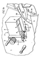
- the apparatus shown in Figures 1a and 1b comprises a front plate 1 mounted to a chassis (not shown), the front plate 1 assisting to define a housing (not shown) in which control means, electrical motive power means, motive power transmission, a vacuum source and a pneumatic power source (all not shown) are housed.
- a splicing head 2 comprising a solid metallic block 3 grooved on its undersurface with a longitudinal tape-receiving groove 4.
- Two sets of three perforations open at the groove surface to provide vacuum shoes 5 and 6 and are connected to the vacuum source within the housing.
- a tape slitting head 7 mounting a blade 8 cooperates with the grooved undersurface of block 3 and is mounted for reciprocatory movement across the groove 4 perpendicular to the plane of front plate 1 by means of fixed shaft 9 upon which slitting head 7 slides. Movement of slitting head 7 is accomplished by displacement of an attached piston (not shown) operated from the pneumatic power source.
- a cross-groove (not shown) in the block 3 intersects groove 4 perpendicular thereto and provides a path for blade 8 to pass across groove 4 in slitting,without contacting the material of the block 3, between vacuum shoes 5 and 6.
- a splicing arm 10 operates beneath the groove 4. Arm 10 has a retracted position in which it is withdrawn into the housing through the splicing arm orifice 31 in the front plate 1, and an operating position in which the arm is displaced from the housing to apply a short length of splicing tape cut from a supply within the housing to abutting tape ends disposed in groove 4. Splicing arm 10 is powered from the vacuum source referred to earlier and operates in conventional manner known in the art.
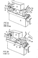
- a cassette holder 11 Adjacent the base of front plate 1, a cassette holder 11 is mounted to a piston 12 for displacement under power from the pneumatic power source between a cassette-receiving position ( Figures 1 a and 1b) in which the holder is relatively forward of plate 1 to facilitate charging of a C-zero cassette thereto, and a cassette-holding position ( Figures 2a to 2i) in which the cassette body is proximate the front plate 1 between inner and outer plates 13 and 14 and ready for a tape loading sequence to begin.
- a cassette-receiving position Figures 1 a and 1b
- a cassette-holding position Figures 2a to 2i
- Two driven hubs 15 and 16 engage the spool sockets (not shown) when the cassette holder is in the cassette-holding position just referred to, hub 15 penetrating opening 17 provided for the purpose in the inner plate 13 of the cassette holder 11.
- the two hubs 15 and 16 terminate driven shafts (not shown) disposed within the housing and powered from the electrical motive power means (ie a wind motor) in conventional manner.
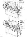
- leader extraction arm 18 and lift arm 19 are received adjacent the underside of cassette leader tape 20, as shown most clearly in Figure 2a.
- Both leader extraction arm 18 and lift arm 19 are displaceable, from the positions just referred to, to withdraw leader tape 20 from the V-zero cassette and dispose it within groove 4 of the splicing head 2 ( Figure 2b), both arms being powered for two-direction movement from the pneumatic power source referred to earlier in conventional manner, for example by using a pnuematic piston-and-cylinder assembly and a ball slide.
- Leader extraction arm 18 is equipped with a cylindrical tape-contacting guide 21 whilst lift arm 19 terminates a vacuum shoe 22 by which tape is retained on its surface by suction.
- a slack arm 23 (not shown in Figures 2a to 2i in the interests of simplicity and clarity of depiction for the other parts) is mounted for reciprocatory movement parallel to the plane of front plate 1, slack arm 23 again being powered from the pneumatic power source.
- the slack arm 23 serves to engage extracted leader tape 20, drawing an excess thereof from the V-zero cassette and then slackening slightly so that it can be ensured that leader tape in groove 4 is not under tension during slitting and splicing.
- the slack arm 23 also controls the position of cut.
- Magnetic tape 26 for supply to the V-zero cassette is supplied from a supply reel 24 and is transported to the splicing head 2 via a system of capstans and guides, as will be seen from the photographs, including a rubber capstan 25.
- a terminal or leading end 27 of magnetic tape 26 is disposed in the groove 4 of block 3 of the splicing head 2.
- leading end 27 of magnetic tape 26 is first guided around the capstan and guide system to the splicing head 2, where it is held in position by means of vacuum supplied to each of vacuum shoes 5 and 6.
- Slitting head 7 then operates and the cut-off tape end is discarded.
- V-zero cassette is then loaded to cassette holder 11 and the holder 11 then displaced inwardly on piston 12.
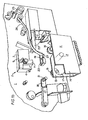
- Leader extraction arm 18 and lift arm 19 are then energized and move to the top of their strokes. The effect of this is to extract leader tape 20 and dispose it in groove 4 so that the leading end 27 of magnetic tape 26 is spaced about 0.25 mm from the leader tape ( Figure 2b), the vacuum shoe 22 of lift arm 19 at the top of its stroke falling similarly short of the surface of groove 4.
- lift arm 19 activates a microswitch (not shown), at the top of its stroke, an air-controlled stop on the slide of the lift arm is activated, the stop defining a position intermediate the lowest position of the stroke of arm 19 and the top of its stroke (as represented in Figures 2d to 2g).
- the slack arm 23 then conditions the cassette (ie the arm 23 is operated to take up leader tape 20 on one of the cassette spools).
- the lift arm 19 is energized, a delay is started on the arm reaching the top of its stroke, after which vacuum is applied to vacuum shoes 5 and 6 in the groove 4 of block 3 and vacuum shoe 22 of lift arm 19 is switched on. This stage in the operating sequence is, of course, also represented by Figure 2b.
- slitting head 7 is activated causing it to move from its rest position, in which it is clear of block 3, towards front plate 1 and then to reciprocate to its rest position ( Figure 2c).
- Leader extraction arm 18 is then raised into tape contact and, with splicing arm 10 retracted, a wind cycle is then commenced, vacuum continuing to be applied to vacuum shoe 22 but vacuum shoes 5 and 6 being deprived of vacuum so as to release the now spliced tape, by activating the wind motors driving hub 15 (Figure 2f).
- wind motors driving hub 15 Figure 2f.
- a second slitting sequence is commenced to slit the tape into two lengths (Figure 2g).
- Lift arm 19 is then activated to bring the leading end of the leader tape 20 (ie the second length referred to earlier) into close proximity (ie about 0.25 mm away) to the length of cut magnetic tape terminating in the leading end from the supply reel 24; leader extraction arm 18 is also de-activated ( Figure 2h). In this condition, so positioned leader has its end essentially butted to the end of the magnetic tape trailing from the cassette.
- a second splicing operation is then effected by activating splicing arm 10 a second time to splice together the trailing end of magnetic tape 26 and the leading end of the leader tape 20 from the other spool of the cassette ( Figure 2i). Further winding at hub 15 after retraction of splicing arm 10, de-activation of vacuum shoe 5 and de-activation of lift arm 19 to the lowest position of its stroke draws the slack loop of tape into the cassette leaving only leader tape exposed at the mouth of the cassette. Continued activation of vacuum shoe 6 retains the leading end of magnetic tape 26 from supply reel 24 within groove 4 in readiness for a further cycle of operations to be conducted with a fresh V-zero cassette.
- Splicing takes place in the apparatus of the invention on a solid block (ie block 3); before the apparatus of the invention, splicing always took place partly on a fixed block and partly on a shift block which yielded under impact from the splicing arm so as to lead to differential adhesion of the splicing tape.
- leader extraction has been referred to as resulting in near contact of the extracted leader with the use tape end retained upon the splicing surface, it is envisaged that actual contact may occur. Whilst the scope of the inventiuon should not exclude methods and apparatus where this circumstance is the case, it should be understood that in practice spacing apart by a small distance is the preferred arrangement (eg about 0.25mm).
Landscapes
- Replacement Of Web Rolls (AREA)
Priority Applications (1)
| Application Number | Priority Date | Filing Date | Title |
|---|---|---|---|
| AT8686305711T ATE105440T1 (de) | 1985-07-24 | 1986-07-24 | Spleissen und laden von band in kassetten. |
Applications Claiming Priority (2)
| Application Number | Priority Date | Filing Date | Title |
|---|---|---|---|
| GB858518748A GB8518748D0 (en) | 1985-07-24 | 1985-07-24 | Splicing & loading tape into cassettes |
| GB8518748 | 1985-07-24 |
Publications (3)
| Publication Number | Publication Date |
|---|---|
| EP0210844A2 true EP0210844A2 (de) | 1987-02-04 |
| EP0210844A3 EP0210844A3 (en) | 1988-03-02 |
| EP0210844B1 EP0210844B1 (de) | 1994-05-04 |
Family
ID=10582820
Family Applications (1)
| Application Number | Title | Priority Date | Filing Date |
|---|---|---|---|
| EP86305711A Expired - Lifetime EP0210844B1 (de) | 1985-07-24 | 1986-07-24 | Spleissen und Laden von Band in Kassetten |
Country Status (4)
| Country | Link |
|---|---|
| EP (1) | EP0210844B1 (de) |
| AT (1) | ATE105440T1 (de) |
| DE (1) | DE3689825D1 (de) |
| GB (2) | GB8518748D0 (de) |
Cited By (2)
| Publication number | Priority date | Publication date | Assignee | Title |
|---|---|---|---|---|
| EP0440160A1 (de) * | 1990-01-31 | 1991-08-07 | Otari Inc. | Gerät zum Laden von Band in Kassetten |
| EP0594923A1 (de) * | 1992-10-30 | 1994-05-04 | TAPEMATIC S.p.A. | Ladeprozess eines Kassettenbandes zur Wiederverwertung von vorher mit Abfallband gefüllten Kassetten und Lademaschine zur Verwirklichung des Prozesses |
Family Cites Families (7)
| Publication number | Priority date | Publication date | Assignee | Title |
|---|---|---|---|---|
| BE758372A (fr) * | 1970-02-09 | 1971-05-03 | King Instrument Corp | Machine a enrouler des bandes |
| US3888480A (en) * | 1971-02-09 | 1975-06-10 | Ottaviano Clerici Bagozzi | Apparatus for loading a magnetic tape into a cassette |
| JPS5110775B1 (de) * | 1971-04-01 | 1976-04-06 | ||
| IT1055492B (it) * | 1976-03-01 | 1981-12-21 | Aeg Telefunken Soc Italiana Pe | Macchina per l avvolgimento di nastri magnetici in casette |
| DE2650457C3 (de) * | 1976-11-04 | 1981-02-12 | Basf Ag, 6700 Ludwigshafen | Vorrichtung zum Laden von Magnetbandkassetten mit Magnetband |
| GB2093801B (en) * | 1981-01-20 | 1985-06-26 | Morgan Scott John Charles | An automatic cassette loading machine |
| JPS5946070B2 (ja) * | 1981-12-30 | 1984-11-10 | 阿波エンジニアリング株式会社 | ビデオテ−プをカセツトのリ−ルに巻き付ける巻付装置 |
-
1985
- 1985-07-24 GB GB858518748A patent/GB8518748D0/en active Pending
-
1986
- 1986-07-24 DE DE3689825T patent/DE3689825D1/de not_active Expired - Lifetime
- 1986-07-24 AT AT8686305711T patent/ATE105440T1/de not_active IP Right Cessation
- 1986-07-24 EP EP86305711A patent/EP0210844B1/de not_active Expired - Lifetime
- 1986-07-24 GB GB8618119A patent/GB2179327B/en not_active Expired - Fee Related
Cited By (3)
| Publication number | Priority date | Publication date | Assignee | Title |
|---|---|---|---|---|
| EP0440160A1 (de) * | 1990-01-31 | 1991-08-07 | Otari Inc. | Gerät zum Laden von Band in Kassetten |
| EP0594923A1 (de) * | 1992-10-30 | 1994-05-04 | TAPEMATIC S.p.A. | Ladeprozess eines Kassettenbandes zur Wiederverwertung von vorher mit Abfallband gefüllten Kassetten und Lademaschine zur Verwirklichung des Prozesses |
| US5806784A (en) * | 1992-10-30 | 1998-09-15 | Tapematic U.S.A., Inc. | Cassette waste tape reloader |
Also Published As
| Publication number | Publication date |
|---|---|
| GB2179327B (en) | 1990-03-21 |
| DE3689825D1 (de) | 1994-06-09 |
| GB8518748D0 (en) | 1985-08-29 |
| EP0210844A3 (en) | 1988-03-02 |
| GB2179327A (en) | 1987-03-04 |
| EP0210844B1 (de) | 1994-05-04 |
| GB8618119D0 (en) | 1986-09-03 |
| ATE105440T1 (de) | 1994-05-15 |
Similar Documents
| Publication | Publication Date | Title |
|---|---|---|
| US4062719A (en) | Apparatus for storing information material in cassettes | |
| US3814343A (en) | Automatic tape loading apparatus for cassettes and the like | |
| GB1485594A (en) | Automatic cassette loading machine | |
| GB1446743A (en) | Splicing head assembly | |
| EP0054566B1 (de) | Verfahren uznd vorrichtung zum automatischen laden von magnetbandkassetten mit neuem bandmaterial | |
| US4497454A (en) | Tape loading machine | |
| US3753834A (en) | Apparatus for splicing magnetic tape | |
| US3888480A (en) | Apparatus for loading a magnetic tape into a cassette | |
| US4385959A (en) | Splicing tape dispenser-applicator | |
| US4911774A (en) | Splicing and loading of tape into cassettes with a stationary splicing block | |
| EP0210844A2 (de) | Spleissen und Laden von Band in Kassetten | |
| US4486262A (en) | Cassette loading machine | |
| US4475970A (en) | Aligning means for tape splicer | |
| US4328065A (en) | Extractor pin | |
| US5066347A (en) | Tape transport apparatus and method of introducing tape thereto | |
| US4648562A (en) | Magnetic tape winding apparatus | |
| US5462631A (en) | Tape winding apparatus | |
| JP2840975B2 (ja) | エンドレス状テープの自動作成方法 | |
| EP0463461B1 (de) | Verfahren und Gerät zum Aufwickeln eines Magnetbandes | |
| GB2283962A (en) | Loading tape into cassettes | |
| WO1992022900A2 (en) | Improved double-pancake loader extractor | |
| US5413290A (en) | Tape winding apparatus | |
| JP4583674B2 (ja) | テープカートリッジの製造方法及び製造装置 | |
| JP2840974B2 (ja) | エンドレス状テープの自動作成方法 | |
| JPH0478539B2 (de) |
Legal Events
| Date | Code | Title | Description |
|---|---|---|---|
| PUAI | Public reference made under article 153(3) epc to a published international application that has entered the european phase |
Free format text: ORIGINAL CODE: 0009012 |
|
| AK | Designated contracting states |
Kind code of ref document: A2 Designated state(s): AT BE CH DE FR GB IT LI LU NL SE |
|
| PUAL | Search report despatched |
Free format text: ORIGINAL CODE: 0009013 |
|
| AK | Designated contracting states |
Kind code of ref document: A3 Designated state(s): AT BE CH DE FR GB IT LI LU NL SE |
|
| 17P | Request for examination filed |
Effective date: 19880901 |
|
| 17Q | First examination report despatched |
Effective date: 19891010 |
|
| RAP1 | Party data changed (applicant data changed or rights of an application transferred) |
Owner name: SONY MAGNESCALE, INC. |
|
| GRAA | (expected) grant |
Free format text: ORIGINAL CODE: 0009210 |
|
| AK | Designated contracting states |
Kind code of ref document: B1 Designated state(s): AT BE CH DE FR GB IT LI LU NL SE |
|
| PG25 | Lapsed in a contracting state [announced via postgrant information from national office to epo] |
Ref country code: IT Free format text: LAPSE BECAUSE OF FAILURE TO SUBMIT A TRANSLATION OF THE DESCRIPTION OR TO PAY THE FEE WITHIN THE PRE;WARNING: LAPSES OF ITALIAN PATENTS WITH EFFECTIVE DATE BEFORE 2007 MAY HAVE OCCURRED AT ANY TIME BEFORE 2007. THE CORRECT EFFECTIVE DATE MAY BE DIFFERENT FROM THE ONE RECORDED.SCRIBED TIME-LIMIT Effective date: 19940504 Ref country code: NL Effective date: 19940504 Ref country code: BE Effective date: 19940504 Ref country code: SE Free format text: THE PATENT HAS BEEN ANNULLED BY A DECISION OF A NATIONAL AUTHORITY Effective date: 19940504 Ref country code: AT Effective date: 19940504 Ref country code: LI Effective date: 19940504 Ref country code: CH Effective date: 19940504 Ref country code: FR Effective date: 19940504 Ref country code: DE Effective date: 19940504 |
|
| REF | Corresponds to: |
Ref document number: 105440 Country of ref document: AT Date of ref document: 19940515 Kind code of ref document: T |
|
| REF | Corresponds to: |
Ref document number: 3689825 Country of ref document: DE Date of ref document: 19940609 |
|
| PG25 | Lapsed in a contracting state [announced via postgrant information from national office to epo] |
Ref country code: LU Free format text: LAPSE BECAUSE OF NON-PAYMENT OF DUE FEES Effective date: 19940731 |
|
| PG25 | Lapsed in a contracting state [announced via postgrant information from national office to epo] |
Ref country code: GB Effective date: 19940804 |
|
| REG | Reference to a national code |
Ref country code: CH Ref legal event code: PL |
|
| EN | Fr: translation not filed | ||
| NLV1 | Nl: lapsed or annulled due to failure to fulfill the requirements of art. 29p and 29m of the patents act | ||
| PLBE | No opposition filed within time limit |
Free format text: ORIGINAL CODE: 0009261 |
|
| STAA | Information on the status of an ep patent application or granted ep patent |
Free format text: STATUS: NO OPPOSITION FILED WITHIN TIME LIMIT |
|
| GBPC | Gb: european patent ceased through non-payment of renewal fee |
Effective date: 19940804 |
|
| 26N | No opposition filed |