EP0210910A2 - Zyklonabscheider mit axialer Strömung - Google Patents
Zyklonabscheider mit axialer Strömung Download PDFInfo
- Publication number
- EP0210910A2 EP0210910A2 EP86401541A EP86401541A EP0210910A2 EP 0210910 A2 EP0210910 A2 EP 0210910A2 EP 86401541 A EP86401541 A EP 86401541A EP 86401541 A EP86401541 A EP 86401541A EP 0210910 A2 EP0210910 A2 EP 0210910A2
- Authority
- EP
- European Patent Office
- Prior art keywords
- tubular body
- downstream
- upstream
- core
- converging
- Prior art date
- Legal status (The legal status is an assumption and is not a legal conclusion. Google has not performed a legal analysis and makes no representation as to the accuracy of the status listed.)
- Withdrawn
Links
- 238000011144 upstream manufacturing Methods 0.000 claims abstract description 28
- 239000012530 fluid Substances 0.000 claims abstract description 15
- 239000002245 particle Substances 0.000 claims abstract description 14
- 230000007423 decrease Effects 0.000 claims abstract description 3
- 238000000926 separation method Methods 0.000 claims description 17
- 230000003247 decreasing effect Effects 0.000 claims description 8
- UYXAWHWODHRRMR-UHFFFAOYSA-N hexobarbital Chemical compound O=C1N(C)C(=O)NC(=O)C1(C)C1=CCCCC1 UYXAWHWODHRRMR-UHFFFAOYSA-N 0.000 claims description 2
- 239000000725 suspension Substances 0.000 claims 1
- 239000000428 dust Substances 0.000 description 4
- 230000001133 acceleration Effects 0.000 description 2
- 230000000694 effects Effects 0.000 description 1
- 230000002349 favourable effect Effects 0.000 description 1
- 239000007788 liquid Substances 0.000 description 1
- 230000005012 migration Effects 0.000 description 1
- 238000013508 migration Methods 0.000 description 1
- 230000002093 peripheral effect Effects 0.000 description 1
- 238000011084 recovery Methods 0.000 description 1
- 230000001105 regulatory effect Effects 0.000 description 1
- 239000007787 solid Substances 0.000 description 1
Images
Classifications
-
- B—PERFORMING OPERATIONS; TRANSPORTING
- B04—CENTRIFUGAL APPARATUS OR MACHINES FOR CARRYING-OUT PHYSICAL OR CHEMICAL PROCESSES
- B04C—APPARATUS USING FREE VORTEX FLOW, e.g. CYCLONES
- B04C3/00—Apparatus in which the axial direction of the vortex flow following a screw-thread type line remains unchanged ; Devices in which one of the two discharge ducts returns centrally through the vortex chamber, a reverse-flow vortex being prevented by bulkheads in the central discharge duct
Definitions
- the subject of the invention is a cyclonal axial flow device intended for the separation of solid or liquid particles suspended in a fluid and constituted by a tubular body comprising a converging upstream portion, a diverging downstream portion and an intermediate portion comprising openings for the evacuation of the separated particles, a core disposed in the axis of said tubular body and extending over the entire length of the tubular body, a vane for rotating the fluid to be purified placed at the inlet end of the tubular body , in the passage formed between the latter and the core, and straightening vanes arranged in said passage between the upstream end of said diverging portion and the outlet end of the tubular body.
- Devices of this type are generally very effective in separating particles whose size is equal to or greater than 10 microns. On the other hand, for particles of smaller dimensions their separation efficiency is lower.
- the object of the present invention is to improve the separation efficiency of these devices, in particular for particles whose dimensions are between 5 and 10 microns.
- the cyclone separation device object of the invention is characterized in that the section of the passage formed between the tubular body and the core has a progressively decreasing section, from upstream to downstream, in the converging portion of the tubular body, and a progressively increasing section, from upstream to downstream, between the upstream end of the divergent portion and the outlet end of the tubular body.
- the straightening vanes can be placed either at the downstream end of the divergent portion of the tubular body, or between its ends.
- the tubular body will comprise a cylindrical portion downstream of the straightening vanes and the core will comprise in this portion of the tubular body a portion whose section decreases progressively from upstream to downstream.
- the part of the core located downstream of the straightening vanes will be cylindrical.
- the openings for the evacuation of the separated particles may be formed by longitudinal slots cut in the downstream part of the converging portion of the tubular body, or in a cylindrical portion comprised between the converging and diverging portions.
- the rotation vane for the fluid to be treated may be placed in the converging portion of the tubular body, near its upstream end, or in a cylindrical portion of the tubular body provided upstream of the converging portion.
- the part of the nucleus extending along the converging portion tubular body may be cylindrical or have a decreasing cross section from upstream to downstream.
- the arrangements according to the invention make it possible to increase the separation efficiency by reducing the thickness of the peripheral boundary layer at the level of the dust evacuation slots and by regulating the profile of the speeds in the fluid stream, which has the effect to promote the migration of particles towards the periphery of the tubular body. They also make it possible to create a form favorable to the collection of dust when several devices of the type described are grouped in a box.
- the invention also makes it possible to reduce the speed of the fluid at the level of the rotation vane and, consequently, its wear.
- the acceleration of rotation in the convergent also considerably improves the separation of dust while maintaining a moderate level of turbulence thanks to the central core which suppresses axial detachments and return currents.
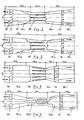
- Figures 1 to 4 of this drawing are views, partially in elevation and partially in section, of four cyclone separation with axial flow produced in accordance with the invention.
- These devices consist of a tubular body of revolution 10 inside which is placed an elongated core 12, of circular section, which extends over the entire length of the body 10 and whose axis coincides with that of the latter.
- the front end of the core 12 is profiled.
- Rotation vanes 14 are provided at the upstream end of the device through which between the fluid to be purified and rectifying vanes 16 are arranged in its downstream part; these blades also serve to support and center the core in the tubular body of the device.
- the body of the apparatus successively comprises, moving in the direction of flow of the fluid indicated by the arrows, an upstream, frustoconical and convergent portion 10a, an intermediate cylindrical portion 10b and a downstream, frustoconical and divergent portion 10c.
- the part 12a of the core between the rotation blades 14 and the connection plane of the portions 10b and 10c has a cylindrical shape
- the part 12b between this plane and the straightening blades 16 has a frustoconical shape, its section increasing regularly from upstream to downstream
- the part 10c located downstream of the blades 16 also has a cylindrical shape.
- Slots longitudinal 18 are cut in the portion 10b of the tubular body 10 for the evacuation of the particles separated from the fluid.
- the portion 10b has been eliminated and replaced by an extension of the frustoconical portion 10a in which the slots are formed 18.
- the shapes of the portion 10c and of the core 12 are the same as in the device of figure 1.
- the tubular body successively comprises, from upstream to downstream, a cylindrical portion 10d, a converging frustoconical portion 10a, a diverging frustoconical portion 10c and a cylindrical portion 10e.
- the rotation vanes 14 are located in the portion 10d, the straightening vanes 16 are located at the connection of the portions 10c and 10e and the slots 18 are formed in the downstream part of the portion 10a.
- the core 12 has a cylindrical shape between the blades 14 and the connection plane of the portions 10a and 10c (part 12a), a frustoconical shape, with increasing section, in the portion 10c (part 12b) and a frustoconical shape, with decreasing section , in the 10th portion (part 12c ').
- the body of the device successively comprises a short portion cylindrical 10d, a converging frustoconical portion 10a, a cylindrical portion 10b, a diverging frustoconical portion 10c and a cylindrical portion 10e.
- the blades 14 are arranged in the portion 10d, immediately upstream of the connection plane of the portions 10a and 10d, the blades 16 are placed in the cylindrical portion 10e, immediately downstream of the connection plane of the portions 10c and 10e and the slots 18 are provided in the downstream part of the cylindrical portion 10b.
- the part 12a 'of the core between the vanes 14 and the connection plane of the portions 10a and 10b of the body of the apparatus has a frustoconical shape, with decreasing section
- the part 12a "located in the portion 10b has a cylindrical shape
- the part 12b located in the portion 10c has a frustoconical shape, with increasing section
- the part 12c 'situated downstream of the straightening vanes 16 has a frustoconical shape, with decreasing section.
- This device will be used in the case of difficult separations because it allows, thanks to the narrowing of the core in the portions 10a and 10b, to obtain a greater centrifugal acceleration for the same radial size of the device.
- the section of the passage formed between the tubular body and the core, in the converging portion 10a has a progressively decreasing section, from upstream to downstream, so as to accelerate the rotation of the fluid and improve the separation dust.
- the section of the passage formed between the tubular body and the core has a progressively increasing section from upstream to downstream, which allows maximum recovery of the kinetic energy of the fluid and, therefore, a significant reduction in pressure drop.
- the angle at the top of the frustoconical part 12b of the core can be equal to or greater than that of the portion 10c of the tubular body, but in all cases the cross section of the passage formed between them increases from upstream to downstream.
Landscapes
- Cyclones (AREA)
Applications Claiming Priority (2)
| Application Number | Priority Date | Filing Date | Title |
|---|---|---|---|
| FR8511445A FR2585266B1 (fr) | 1985-07-26 | 1985-07-26 | Appareil de separation cyclonaire a ecoulement axial |
| FR8511445 | 1985-07-26 |
Publications (2)
| Publication Number | Publication Date |
|---|---|
| EP0210910A2 true EP0210910A2 (de) | 1987-02-04 |
| EP0210910A3 EP0210910A3 (de) | 1988-04-13 |
Family
ID=9321671
Family Applications (1)
| Application Number | Title | Priority Date | Filing Date |
|---|---|---|---|
| EP86401541A Withdrawn EP0210910A3 (de) | 1985-07-26 | 1986-07-10 | Zyklonabscheider mit axialer Strömung |
Country Status (2)
| Country | Link |
|---|---|
| EP (1) | EP0210910A3 (de) |
| FR (1) | FR2585266B1 (de) |
Cited By (6)
| Publication number | Priority date | Publication date | Assignee | Title |
|---|---|---|---|---|
| NL1010478C2 (nl) * | 1998-11-04 | 2000-05-08 | Cds Engineering B V | Inrichting voor het behandelen van een gas/vloeistofmengsel. |
| WO2003066195A1 (en) * | 2002-02-08 | 2003-08-14 | Norsk Hydro Asa | Device for the transformation of gas/liquid flow to laminar or stratified flow |
| EP1512453A1 (de) * | 2003-08-30 | 2005-03-09 | Mann+Hummel Gmbh | Vorrichtung zur Trennung von Partikeln aus einem Medienstrom |
| EP1974790A1 (de) * | 2007-03-26 | 2008-10-01 | Twister B.V. | Zyklonabscheider für Flüssigkeiten |
| WO2010090510A1 (en) * | 2009-02-05 | 2010-08-12 | Twister B.V. | Multistage cyclonic fluid separator |
| NL2028048A (en) * | 2020-06-16 | 2022-01-19 | Univ China Petroleum | Full-swirl supersonic separation device |
Family Cites Families (5)
| Publication number | Priority date | Publication date | Assignee | Title |
|---|---|---|---|---|
| US2201301A (en) * | 1937-03-30 | 1940-05-21 | Western Precipitation Corp | Centrifugal separating device |
| US2370629A (en) * | 1943-06-02 | 1945-03-06 | William R Appeldoorn | Dust precipitator |
| US2487633A (en) * | 1947-01-29 | 1949-11-08 | Jr Joseph Breslove | Separator |
| GB711304A (en) * | 1951-01-12 | 1954-06-30 | Svenska Flaektfabriken Ab | Device for separating dust |
| FR1069071A (fr) * | 1952-10-27 | 1954-07-05 | Airmeca | Perfectionnements aux capteurs de particules contenues dans des fluides |
-
1985
- 1985-07-26 FR FR8511445A patent/FR2585266B1/fr not_active Expired - Fee Related
-
1986
- 1986-07-10 EP EP86401541A patent/EP0210910A3/de not_active Withdrawn
Cited By (19)
| Publication number | Priority date | Publication date | Assignee | Title |
|---|---|---|---|---|
| WO2000025931A1 (en) * | 1998-11-04 | 2000-05-11 | Spark Technologies And Innovations N.V. | Device for treating a gas/liquid mixture |
| US7163626B1 (en) | 1998-11-04 | 2007-01-16 | Spark Technologies And Innovations N.V. | Device for treating a gas/liquid mixture |
| NL1010478C2 (nl) * | 1998-11-04 | 2000-05-08 | Cds Engineering B V | Inrichting voor het behandelen van een gas/vloeistofmengsel. |
| US7559975B2 (en) | 2002-02-08 | 2009-07-14 | Norsk Hydro Asa | Process for transforming gas/liquid flow into laminar or stratified flow |
| WO2003066195A1 (en) * | 2002-02-08 | 2003-08-14 | Norsk Hydro Asa | Device for the transformation of gas/liquid flow to laminar or stratified flow |
| CN1308056C (zh) * | 2002-02-08 | 2007-04-04 | 诺尔斯海德公司 | 将气/液流转化成层流或片流的装置 |
| AU2003206266B2 (en) * | 2002-02-08 | 2008-07-17 | Equinor Energy As | Device for the transformation of gas/liquid flow to laminar or stratified flow |
| EP1512453A1 (de) * | 2003-08-30 | 2005-03-09 | Mann+Hummel Gmbh | Vorrichtung zur Trennung von Partikeln aus einem Medienstrom |
| US7258727B2 (en) | 2003-08-30 | 2007-08-21 | Mann & Hummel Gmbh | Apparatus for separating particles from a flowing medium |
| EP1974790A1 (de) * | 2007-03-26 | 2008-10-01 | Twister B.V. | Zyklonabscheider für Flüssigkeiten |
| WO2008116732A1 (en) * | 2007-03-26 | 2008-10-02 | Twister B.V. | Cyclonic fluid separator |
| RU2424038C2 (ru) * | 2007-03-26 | 2011-07-20 | Твистер Б.В. | Циклонный сепаратор для текучих сред |
| CN101678257B (zh) * | 2007-03-26 | 2011-08-24 | 缠绕机公司 | 旋流分离器 |
| AU2008231954B2 (en) * | 2007-03-26 | 2012-01-19 | Twister B.V. | Cyclonic fluid separator |
| US8475555B2 (en) | 2007-03-26 | 2013-07-02 | Twister B.V. | Cyclonic fluid separator |
| WO2010090510A1 (en) * | 2009-02-05 | 2010-08-12 | Twister B.V. | Multistage cyclonic fluid separator |
| CN102369407B (zh) * | 2009-02-05 | 2015-01-28 | 缠绕机公司 | 多级旋流分离器 |
| US9034082B2 (en) | 2009-02-05 | 2015-05-19 | Twister B.V. | Multistage cyclonic fluid separator |
| NL2028048A (en) * | 2020-06-16 | 2022-01-19 | Univ China Petroleum | Full-swirl supersonic separation device |
Also Published As
| Publication number | Publication date |
|---|---|
| EP0210910A3 (de) | 1988-04-13 |
| FR2585266B1 (fr) | 1990-05-11 |
| FR2585266A1 (fr) | 1987-01-30 |
Similar Documents
| Publication | Publication Date | Title |
|---|---|---|
| EP0028996B1 (de) | Zentrifugalzyklonabscheider | |
| CA1285539C (fr) | Separateur tournant a vortex pour liquide heterogene | |
| EP2147710B1 (de) | Vorrichtung zum Abtrennen von Feststoffpartikeln aus Wasser sowie hydraulische Einrichtung mit einer solchen Abtrennvorrichtung | |
| FR2907519A1 (fr) | Nageoire de plateforme de soufflante | |
| FR2645184A1 (fr) | Appareil de fluidisation, de degazage et de pompage d'une suspension d'une matiere cellulosique fibreuse | |
| US20030006188A1 (en) | Separator for liquids containing impurities | |
| EP0162441A2 (de) | Zentrifugalseparator für Gemische | |
| EP0210910A2 (de) | Zyklonabscheider mit axialer Strömung | |
| EP0104966B1 (de) | Zentrifuge mit Energierückgewinnung | |
| FR2588778A1 (fr) | Separateur a vortex liquide | |
| EP3174637B1 (de) | Zyklonvorrichtung mit zwei zyklonen die mit einem optimiertem rohrsystem verbunden sind | |
| FR2626322A1 (fr) | Roue a ailettes de compresseur centrifuge | |
| EP0341553A1 (de) | Kreiselpumpe | |
| BE502624A (de) | ||
| FR2681259A1 (fr) | Cellule cyclonique a entree axiale et passage direct et appareil d'epuration de fluide en faisant application. | |
| BE440285A (de) | ||
| WO2013132190A1 (fr) | Générateurs de vortex placés dans le canal inter-aubes d'un redresseur de compresseur | |
| EP0404923A1 (de) | Trennschleuder mit einer vorrichtung zur umwandlung von kinetischer energie in druck. | |
| EP0082775B1 (de) | Schornsteinaufsatz für gasförmiges Fluid | |
| FR2757210A1 (fr) | Echappement centrifuge de turbine a deflecteur cambre | |
| FR2613956A1 (fr) | Procede et dispositif de separation centrifuge d'un melange de plusieurs phases | |
| FR2670402A1 (fr) | Cyclone comprenant un redresseur d'ecoulement de la transformation d'un flux tourbillonnaire en un ecoulement lineaire. | |
| BE465361A (de) | ||
| FR2660580A1 (fr) | Dispositif de recuperation d'energie cinetique d'un fluide en rotation. | |
| FR2703602A1 (fr) | Procédé de séparation de produits particulaires de densités différentes en suspension dans un fluide et dispositif pour sa mise en Óoeuvre. |
Legal Events
| Date | Code | Title | Description |
|---|---|---|---|
| PUAI | Public reference made under article 153(3) epc to a published international application that has entered the european phase |
Free format text: ORIGINAL CODE: 0009012 |
|
| AK | Designated contracting states |
Kind code of ref document: A2 Designated state(s): BE IT NL |
|
| PUAL | Search report despatched |
Free format text: ORIGINAL CODE: 0009013 |
|
| AK | Designated contracting states |
Kind code of ref document: A3 Designated state(s): BE IT NL |
|
| STAA | Information on the status of an ep patent application or granted ep patent |
Free format text: STATUS: THE APPLICATION IS DEEMED TO BE WITHDRAWN |
|
| 18D | Application deemed to be withdrawn |
Effective date: 19881014 |
|
| RIN1 | Information on inventor provided before grant (corrected) |
Inventor name: REBOURS, ALBERT Inventor name: MERLE, JEAN |