EP0210924A2 - Selbsttätiges Sphygmomanometer - Google Patents
Selbsttätiges Sphygmomanometer Download PDFInfo
- Publication number
- EP0210924A2 EP0210924A2 EP86401650A EP86401650A EP0210924A2 EP 0210924 A2 EP0210924 A2 EP 0210924A2 EP 86401650 A EP86401650 A EP 86401650A EP 86401650 A EP86401650 A EP 86401650A EP 0210924 A2 EP0210924 A2 EP 0210924A2
- Authority
- EP
- European Patent Office
- Prior art keywords
- pump
- compartment
- automatic sphygmomanometer
- sphygmomanometer according
- blood pressure
- Prior art date
- Legal status (The legal status is an assumption and is not a legal conclusion. Google has not performed a legal analysis and makes no representation as to the accuracy of the status listed.)
- Granted
Links
- 230000036772 blood pressure Effects 0.000 claims abstract description 12
- 229920001821 foam rubber Polymers 0.000 claims description 11
- 210000004204 blood vessel Anatomy 0.000 claims description 2
- 238000009530 blood pressure measurement Methods 0.000 abstract description 4
- 229920001971 elastomer Polymers 0.000 description 5
- 238000012986 modification Methods 0.000 description 5
- 230000004048 modification Effects 0.000 description 5
- 238000001514 detection method Methods 0.000 description 3
- 239000012212 insulator Substances 0.000 description 2
- 208000019901 Anxiety disease Diseases 0.000 description 1
- 230000002159 abnormal effect Effects 0.000 description 1
- 230000002411 adverse Effects 0.000 description 1
- 230000036506 anxiety Effects 0.000 description 1
- 230000005540 biological transmission Effects 0.000 description 1
- 238000010276 construction Methods 0.000 description 1
- 238000013016 damping Methods 0.000 description 1
- 230000003292 diminished effect Effects 0.000 description 1
- 230000003340 mental effect Effects 0.000 description 1
- 230000002093 peripheral effect Effects 0.000 description 1
- 238000007789 sealing Methods 0.000 description 1
Images

Classifications
-
- A—HUMAN NECESSITIES
- A61—MEDICAL OR VETERINARY SCIENCE; HYGIENE
- A61B—DIAGNOSIS; SURGERY; IDENTIFICATION
- A61B5/00—Measuring for diagnostic purposes; Identification of persons
- A61B5/02—Detecting, measuring or recording for evaluating the cardiovascular system, e.g. pulse, heart rate, blood pressure or blood flow
-
- A—HUMAN NECESSITIES
- A61—MEDICAL OR VETERINARY SCIENCE; HYGIENE
- A61B—DIAGNOSIS; SURGERY; IDENTIFICATION
- A61B5/00—Measuring for diagnostic purposes; Identification of persons
- A61B5/02—Detecting, measuring or recording for evaluating the cardiovascular system, e.g. pulse, heart rate, blood pressure or blood flow
- A61B5/021—Measuring pressure in heart or blood vessels
- A61B5/022—Measuring pressure in heart or blood vessels by applying pressure to close blood vessels, e.g. against the skin; Ophthalmodynamometers
Definitions
- This invention relates to an automatic sphygmomanometer having an internal pneumatic pump used in pressurizing a cuff wrapped around an arm of a patient when measuring blood pressure.
- a conventional approach is to support the pump by means such as rubber vibration insulator.
- the rubber vibration insulator is in mechanical contact with the pump and is itself mechanically joined to the case of the sphygmomanometer, pump vibration is diminished in dependence solely upon the damping factor of the rubber.
- a sphygmomanometer has an overall weight of about 1 kg, it is not possible with the conventional arrangement to absorb the vibration energy because of the mass of the sphygmomanometer, and there is the affair that the entire sphygmomanometer may resonate due to the vibration set up by the pump.
- the present invention is contrived in the light of the above-mentioned circumstances and an object of the present invention is to provide an automatic sphygmomanometer adapted to prevent vibration and noise produced by a pneumatic pump from being transmitted to the exterior of the sphygmomanometer, thereby minimizing the adverse influence of such stimuli on blood pressure measurement.
- the foregoing object is attained by providing an automatic sphygmomanometer in which a compartment accommodating a pneumatic pump in its entirety is provided within the case of the automatic sphygmomanometer.
- the pneumatic pump is supported within the compartment by resilient means so as not to contact the walls of the compartment.
- the automatic sphygmomanometer further includes means for sealing the compartment.
- an automatic sphygmomanometer 10 comprising a sphygmomanometer instrument package 12, a cuff 14 wrapped around the arm of a patient and serving as a sensor for sensing the patient's blood pressure, and a pipe 16 connecting the instrument package 12 and the cuff 14.
- the instrument package 12 is constituted by a detection system for detecting Korotkoff sounds, via the cuff 14, produced by the patient's blood vessels kept under pressure by the cuff, and for determining the patient's blood pressure from the applied pressure and the Korotkoff sounds.
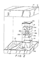
- the sphygmomanometer instrument package 12 comprises a case 18, a pneumatic pump 20 disposed within the case 18 for feeding compressed air into the cuff 14 via the connecting pipe 16, an arithmetic unit 22 for calculating blood pressure automatically from the Korotkoff sounds sensed by the cuff 14 and the pressure applied to the cuff 14, and a display means for displaying the blood pressure calculated by the arithmetic unit.
- the case 18 is equipped with a compartment 24 sized to be larger than the pneumatic pump 20 for internally accommodating the same.
- the pneumatic pump 20 comprises a pump body 20a for emitting compressed air, and a motor 20b for driving the pump body 20a.
- the motor 20b drives an eccentric shaft, not shown, to move a diaphragm, not shown, up and down, thereby producing compressed air.
- the pneumatic pump 20 is accommodated within the compartment 24 in state where the entirety of the pump 20 is covered by a resilient body, such as a rubber foam body 26, serving as resilient means for resiliently supporting the pump 20 within the compartment 24.
- the rubber foam body 26 has, for example, a density of 15.8 kg/m3.
- the compartment 24 defines a space delimited by a box 24a open at its top, and an openable lid 24b closing the open top of the box 24a.
- the rubber foam body 26 comprises first and second halves 26a, 26b capable of being brought together in face-to-face contact.
- the second half 26b of the rubber foam body 26 is formed to include a recess 28b for receiving approximately the lower half of the pneumatic pump 20.
- the first half 26a of the rubber body 26 is also formed to include a similar recess 28a (not shown in Fig.2) for receiving approximately the upper half of the pump 20.
- a similar recess 28a (not shown in Fig.2) for receiving approximately the upper half of the pump 20.
- the compressed air produced by the pneumatic pump 20 is fed into the connecting pipe 16.
- the case 18 of instrument package 12 is formed to include a recess 12a in its rear side.
- the recess 12a is connected to the pneumatic pump 20 by a connecting tube 30.
- a connector 32 Removably inserted in the recess 12a is a connector 32, which is sealed with respect to the peripheral surface of the recess 12a by an O-ring 34.
- a seal is provided between the connecting tube 30 and the compartment 24 by a thin rubber bushing 36.
- the pneumatic pump 20 is fully enveloped by the rubber foam body 26, in which state the pump is accommodated within the compartment 24.
- This enables the vibration of the pneumatic pump 26 to be absorbed by the rubber foam body 26 so that the amount of such vibration leaking to the exterior of the instrument package 12 may be suppressed.
- Almost all noise from the pneumatic pump 20 is also prevented from leaking to the outside by virtue of the compartment 24, which is sealed by the box 24a and lid 24b.
- the pneumatic pump 20 which is a source of both noise and vibration, is accommodated within the compartment 24 in a state closely enveloped by the rubber foam body 26, and the compartment 24 is sealed. As a result, external transmission of the noise and vibration ascribable to the pneumatic pump 20 are suppressed.
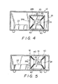
- each spring 40 has one end thereof attached to the inner wall of the compartment 24, and has its other end attached to the pump 20.
- the pneumatic pump 20 is suspended in a floating state within the space of the compartment 24 by means of the springs 40.
- FIG. 5 Still another modification is illustrated in Fig. 5, in which the ceiling of the case 18 also serves as the lid of the compartment 24.
- the open side of the box 24a defining the compartment 24 is not closed merely by a separate lid. Instead, a portion of the case 18 serves to seal the compartment 24.
- the blood pressure detection system is well-suited for application to arrangements that rely upon detection of Korotkoff sounds.
- the system is not limited to a Korotkoff sound detecting arrangement but can also be applied to a system in which blood pressure is sensed by oscillometry.
Landscapes
- Health & Medical Sciences (AREA)
- Life Sciences & Earth Sciences (AREA)
- Cardiology (AREA)
- Vascular Medicine (AREA)
- Biomedical Technology (AREA)
- Molecular Biology (AREA)
- Physiology (AREA)
- Biophysics (AREA)
- Pathology (AREA)
- Engineering & Computer Science (AREA)
- Veterinary Medicine (AREA)
- Heart & Thoracic Surgery (AREA)
- Medical Informatics (AREA)
- Physics & Mathematics (AREA)
- Surgery (AREA)
- Animal Behavior & Ethology (AREA)
- General Health & Medical Sciences (AREA)
- Public Health (AREA)
- Ophthalmology & Optometry (AREA)
- Measuring Pulse, Heart Rate, Blood Pressure Or Blood Flow (AREA)
- Reciprocating Pumps (AREA)
Applications Claiming Priority (2)
| Application Number | Priority Date | Filing Date | Title |
|---|---|---|---|
| JP1985112941U JPS6221304U (de) | 1985-07-25 | 1985-07-25 | |
| JP112941/85U | 1985-07-25 |
Publications (3)
| Publication Number | Publication Date |
|---|---|
| EP0210924A2 true EP0210924A2 (de) | 1987-02-04 |
| EP0210924A3 EP0210924A3 (en) | 1987-10-07 |
| EP0210924B1 EP0210924B1 (de) | 1991-09-25 |
Family
ID=14599334
Family Applications (1)
| Application Number | Title | Priority Date | Filing Date |
|---|---|---|---|
| EP86401650A Expired - Lifetime EP0210924B1 (de) | 1985-07-25 | 1986-07-23 | Selbsttätiges Sphygmomanometer |
Country Status (5)
| Country | Link |
|---|---|
| US (1) | US5092338A (de) |
| EP (1) | EP0210924B1 (de) |
| JP (1) | JPS6221304U (de) |
| KR (2) | KR870000905A (de) |
| DE (1) | DE3681650D1 (de) |
Families Citing this family (6)
| Publication number | Priority date | Publication date | Assignee | Title |
|---|---|---|---|---|
| US5285791A (en) * | 1992-01-21 | 1994-02-15 | Siemens Medical Electronics, Inc. | Noise damping system for an automatic blood pressure gauge |
| US6095983A (en) * | 1998-07-24 | 2000-08-01 | Welch Allyn, Inc. | Electro-pneumatic assembly for blood pressure cuff |
| US7699787B2 (en) * | 2005-10-25 | 2010-04-20 | Welch Allyn, Inc. | Modular blood pressure measurement apparatus |
| DE102019109928A1 (de) * | 2019-04-15 | 2020-10-15 | Alfmeier Präzision SE | Pumpengehäuse, Pumpe und Sitz |
| US11998117B2 (en) * | 2019-10-22 | 2024-06-04 | Shenzhen Glamour Technology Co., Ltd | Silent air pump box and intelligent adjustment mattress |
| EP4403101A1 (de) * | 2023-01-20 | 2024-07-24 | Shenzhen Jamr Technology Co., Ltd. | Luftregelungsmechanismus und sphygmomanometer |
Citations (1)
| Publication number | Priority date | Publication date | Assignee | Title |
|---|---|---|---|---|
| GB2060175A (en) | 1979-10-03 | 1981-04-29 | United States Surgical Corp | Automatic blood pressure measurement |
Family Cites Families (14)
| Publication number | Priority date | Publication date | Assignee | Title |
|---|---|---|---|---|
| US3527204A (en) * | 1965-05-28 | 1970-09-08 | Ibm | Pressure cuff system |
| US3405288A (en) * | 1966-02-25 | 1968-10-08 | William A. Dittrich | Sound and vibration detector device |
| US3905353A (en) * | 1974-02-28 | 1975-09-16 | Medical Monitors Inc | Blood pressure apparatus |
| US4088126A (en) * | 1976-05-24 | 1978-05-09 | Gemind John M | Device for measuring blood pressure |
| EP0014085A1 (de) * | 1979-01-30 | 1980-08-06 | Glynwed Group Services Limited | Luftkompressoranlage |
| US4371143A (en) * | 1980-05-24 | 1983-02-01 | Mitsubishi Steel Mfg. Co., Ltd. | Earthquake isolation floor |
| US4378807A (en) * | 1980-12-03 | 1983-04-05 | Clinical Data, Inc. | Blood pressure measurement apparatus |
| JPS57200741A (en) * | 1981-06-03 | 1982-12-09 | Nissan Motor Co Ltd | Power unit mount body of car |
| JPS58103434A (ja) * | 1981-12-16 | 1983-06-20 | 株式会社日立製作所 | 血圧計 |
| NL8204005A (nl) * | 1982-10-18 | 1984-05-16 | Philips Nv | Koelsysteem met twee-traps compressie-inrichting. |
| EP0145208A1 (de) * | 1983-11-04 | 1985-06-19 | SEIKO INSTRUMENTS & ELECTRONICS LTD. | Elektronisches Sphygmomanometer |
| US4679759A (en) * | 1984-12-24 | 1987-07-14 | Ford Motor Company | Assembly for mounting a vibrating body |
| US4646754A (en) * | 1985-02-19 | 1987-03-03 | Seale Joseph B | Non-invasive determination of mechanical characteristics in the body |
| DE3602135C1 (de) * | 1986-01-24 | 1992-07-02 | Bayerische Motoren Werke Ag | Lagerung einer Kraftstoffpumpe im Kraftstoffvorratsbehaelter eines Kraftfahrzeuges |
-
1985
- 1985-07-25 JP JP1985112941U patent/JPS6221304U/ja active Pending
-
1986
- 1986-07-23 EP EP86401650A patent/EP0210924B1/de not_active Expired - Lifetime
- 1986-07-23 DE DE8686401650T patent/DE3681650D1/de not_active Expired - Fee Related
- 1986-07-24 KR KR1019860006054A patent/KR870000905A/ko not_active Withdrawn
- 1986-07-24 KR KR868606054U patent/KR890003515Y1/ko not_active Expired
-
1990
- 1990-02-22 US US07/483,121 patent/US5092338A/en not_active Expired - Fee Related
Patent Citations (1)
| Publication number | Priority date | Publication date | Assignee | Title |
|---|---|---|---|---|
| GB2060175A (en) | 1979-10-03 | 1981-04-29 | United States Surgical Corp | Automatic blood pressure measurement |
Also Published As
| Publication number | Publication date |
|---|---|
| JPS6221304U (de) | 1987-02-09 |
| KR890003515Y1 (en) | 1989-05-27 |
| DE3681650D1 (de) | 1991-10-31 |
| EP0210924A3 (en) | 1987-10-07 |
| US5092338A (en) | 1992-03-03 |
| EP0210924B1 (de) | 1991-09-25 |
| KR870000905A (ko) | 1987-03-10 |
Similar Documents
| Publication | Publication Date | Title |
|---|---|---|
| JP4116444B2 (ja) | 疾病症状を検出するのに使用する非侵襲性プローブ | |
| US4299233A (en) | Patient monitoring device and method | |
| US3818765A (en) | Device for sterile measurement of liquid or gas pressures | |
| US5103832A (en) | Biological pressure transducer zeroing and levelling reference apparatus | |
| US3865100A (en) | Apparatus for measuring blood pressure | |
| US5438868A (en) | Noninvasive ultrasonic liquid level indicator | |
| CA1187946A (en) | Pressure monitoring method and apparatus | |
| EP0094183A2 (de) | Abstimmbares Stethoskop | |
| CA2005297A1 (en) | Gel-filled blood pressure transducer | |
| EP0371009A3 (de) | Drainagevorrichtung mit Absaugung oder freiem Abfluss | |
| EP0210924A2 (de) | Selbsttätiges Sphygmomanometer | |
| US5014970A (en) | Body member positioner | |
| JP4403588B2 (ja) | 生体音検出装置 | |
| US5578799A (en) | Patient-to-transducer interface device | |
| US4890625A (en) | Blood pressure cuff with integral acoustic pickup cup | |
| US3032030A (en) | Sphygmomanometer | |
| US4732159A (en) | Simple capsule pneumograph | |
| US6099486A (en) | Precordial monitoring apparatus | |
| JP2024140911A (ja) | 生体音聴診装置 | |
| FI94287C (fi) | Häiriönvaimennusmenetelmä ja anturikonstruktio signaalin mittaamiseksi kiinteän aineen pinnalta | |
| US2833274A (en) | Sphygmomanometer | |
| JPS6029132A (ja) | 感覚検査装置用検出部 | |
| CN217987557U (zh) | 气泵固定结构及电子血压计 | |
| CN203379112U (zh) | 航海用血压测量装置 | |
| JP3687546B2 (ja) | 血圧計 |
Legal Events
| Date | Code | Title | Description |
|---|---|---|---|
| PUAI | Public reference made under article 153(3) epc to a published international application that has entered the european phase |
Free format text: ORIGINAL CODE: 0009012 |
|
| 17P | Request for examination filed |
Effective date: 19860726 |
|
| AK | Designated contracting states |
Kind code of ref document: A2 Designated state(s): BE DE FR GB NL |
|
| RAP1 | Party data changed (applicant data changed or rights of an application transferred) |
Owner name: TERUMO KABUSHIKI KAISHA TRADING AS TERUMO CORPORAT |
|
| PUAL | Search report despatched |
Free format text: ORIGINAL CODE: 0009013 |
|
| AK | Designated contracting states |
Kind code of ref document: A3 Designated state(s): BE DE FR GB NL |
|
| 17Q | First examination report despatched |
Effective date: 19890710 |
|
| GRAA | (expected) grant |
Free format text: ORIGINAL CODE: 0009210 |
|
| AK | Designated contracting states |
Kind code of ref document: B1 Designated state(s): BE DE FR GB NL |
|
| REF | Corresponds to: |
Ref document number: 3681650 Country of ref document: DE Date of ref document: 19911031 |
|
| ET | Fr: translation filed | ||
| PLBE | No opposition filed within time limit |
Free format text: ORIGINAL CODE: 0009261 |
|
| STAA | Information on the status of an ep patent application or granted ep patent |
Free format text: STATUS: NO OPPOSITION FILED WITHIN TIME LIMIT |
|
| 26N | No opposition filed | ||
| PGFP | Annual fee paid to national office [announced via postgrant information from national office to epo] |
Ref country code: FR Payment date: 19950711 Year of fee payment: 10 |
|
| PGFP | Annual fee paid to national office [announced via postgrant information from national office to epo] |
Ref country code: GB Payment date: 19950712 Year of fee payment: 10 |
|
| PGFP | Annual fee paid to national office [announced via postgrant information from national office to epo] |
Ref country code: DE Payment date: 19950725 Year of fee payment: 10 |
|
| PGFP | Annual fee paid to national office [announced via postgrant information from national office to epo] |
Ref country code: NL Payment date: 19950727 Year of fee payment: 10 |
|
| PGFP | Annual fee paid to national office [announced via postgrant information from national office to epo] |
Ref country code: BE Payment date: 19950911 Year of fee payment: 10 |
|
| PG25 | Lapsed in a contracting state [announced via postgrant information from national office to epo] |
Ref country code: GB Effective date: 19960723 |
|
| PG25 | Lapsed in a contracting state [announced via postgrant information from national office to epo] |
Ref country code: BE Effective date: 19960731 |
|
| BERE | Be: lapsed |
Owner name: TERUMO K.K. TRADING AS TERUMO CORP. Effective date: 19960731 |
|
| PG25 | Lapsed in a contracting state [announced via postgrant information from national office to epo] |
Ref country code: NL Effective date: 19970201 |
|
| GBPC | Gb: european patent ceased through non-payment of renewal fee |
Effective date: 19960723 |
|
| PG25 | Lapsed in a contracting state [announced via postgrant information from national office to epo] |
Ref country code: FR Effective date: 19970328 |
|
| NLV4 | Nl: lapsed or anulled due to non-payment of the annual fee |
Effective date: 19970201 |
|
| PG25 | Lapsed in a contracting state [announced via postgrant information from national office to epo] |
Ref country code: DE Effective date: 19970402 |
|
| REG | Reference to a national code |
Ref country code: FR Ref legal event code: ST |