EP0210927A1 - Resolver zur Bestimmung des Positionswinkels eines drehenden Organs - Google Patents
Resolver zur Bestimmung des Positionswinkels eines drehenden Organs Download PDFInfo
- Publication number
- EP0210927A1 EP0210927A1 EP86401665A EP86401665A EP0210927A1 EP 0210927 A1 EP0210927 A1 EP 0210927A1 EP 86401665 A EP86401665 A EP 86401665A EP 86401665 A EP86401665 A EP 86401665A EP 0210927 A1 EP0210927 A1 EP 0210927A1
- Authority
- EP
- European Patent Office
- Prior art keywords
- winding
- resolver
- support
- resolver according
- windings
- Prior art date
- Legal status (The legal status is an assumption and is not a legal conclusion. Google has not performed a legal analysis and makes no representation as to the accuracy of the status listed.)
- Withdrawn
Links
Images



Classifications
-
- G—PHYSICS
- G01—MEASURING; TESTING
- G01D—MEASURING NOT SPECIALLY ADAPTED FOR A SPECIFIC VARIABLE; ARRANGEMENTS FOR MEASURING TWO OR MORE VARIABLES NOT COVERED IN A SINGLE OTHER SUBCLASS; TARIFF METERING APPARATUS; MEASURING OR TESTING NOT OTHERWISE PROVIDED FOR
- G01D5/00—Mechanical means for transferring the output of a sensing member; Means for converting the output of a sensing member to another variable where the form or nature of the sensing member does not constrain the means for converting; Transducers not specially adapted for a specific variable
- G01D5/12—Mechanical means for transferring the output of a sensing member; Means for converting the output of a sensing member to another variable where the form or nature of the sensing member does not constrain the means for converting; Transducers not specially adapted for a specific variable using electric or magnetic means
- G01D5/14—Mechanical means for transferring the output of a sensing member; Means for converting the output of a sensing member to another variable where the form or nature of the sensing member does not constrain the means for converting; Transducers not specially adapted for a specific variable using electric or magnetic means influencing the magnitude of a current or voltage
- G01D5/242—Mechanical means for transferring the output of a sensing member; Means for converting the output of a sensing member to another variable where the form or nature of the sensing member does not constrain the means for converting; Transducers not specially adapted for a specific variable using electric or magnetic means influencing the magnitude of a current or voltage by carrying output of an electrodynamic device, e.g. a tachodynamo
-
- G—PHYSICS
- G01—MEASURING; TESTING
- G01D—MEASURING NOT SPECIALLY ADAPTED FOR A SPECIFIC VARIABLE; ARRANGEMENTS FOR MEASURING TWO OR MORE VARIABLES NOT COVERED IN A SINGLE OTHER SUBCLASS; TARIFF METERING APPARATUS; MEASURING OR TESTING NOT OTHERWISE PROVIDED FOR
- G01D5/00—Mechanical means for transferring the output of a sensing member; Means for converting the output of a sensing member to another variable where the form or nature of the sensing member does not constrain the means for converting; Transducers not specially adapted for a specific variable
- G01D5/12—Mechanical means for transferring the output of a sensing member; Means for converting the output of a sensing member to another variable where the form or nature of the sensing member does not constrain the means for converting; Transducers not specially adapted for a specific variable using electric or magnetic means
- G01D5/14—Mechanical means for transferring the output of a sensing member; Means for converting the output of a sensing member to another variable where the form or nature of the sensing member does not constrain the means for converting; Transducers not specially adapted for a specific variable using electric or magnetic means influencing the magnitude of a current or voltage
- G01D5/20—Mechanical means for transferring the output of a sensing member; Means for converting the output of a sensing member to another variable where the form or nature of the sensing member does not constrain the means for converting; Transducers not specially adapted for a specific variable using electric or magnetic means influencing the magnitude of a current or voltage by varying inductance, e.g. by a movable armature
- G01D5/204—Mechanical means for transferring the output of a sensing member; Means for converting the output of a sensing member to another variable where the form or nature of the sensing member does not constrain the means for converting; Transducers not specially adapted for a specific variable using electric or magnetic means influencing the magnitude of a current or voltage by varying inductance, e.g. by a movable armature by influencing the mutual induction between two or more coils
- G01D5/2046—Mechanical means for transferring the output of a sensing member; Means for converting the output of a sensing member to another variable where the form or nature of the sensing member does not constrain the means for converting; Transducers not specially adapted for a specific variable using electric or magnetic means influencing the magnitude of a current or voltage by varying inductance, e.g. by a movable armature by influencing the mutual induction between two or more coils by a movable ferromagnetic element, e.g. a core
-
- H—ELECTRICITY
- H02—GENERATION; CONVERSION OR DISTRIBUTION OF ELECTRIC POWER
- H02K—DYNAMO-ELECTRIC MACHINES
- H02K24/00—Machines adapted for the instantaneous transmission or reception of the angular displacement of rotating parts, e.g. synchro, selsyn
Definitions
- the present invention relates to a resolver for locating the angular position of a rotating member, comprising a rotor, a stator, a primary winding to which a voltage is applied and secondary windings in which electromotive forces are developed serving to locate the angular position of the rotor.
- a resolver is a micromachine providing voltages which are a function of the position of the rotor. These potential differences characterize the angular position of the rotor.
- resolvers such as that described in French patent 2,452,818 include a stator with two windings and a rotor with one winding receiving a sinusoidal alternating voltage.
- the voltages obtained across the stator windings make it possible, by means of an electronic device, to identify the angular position of the rotor.
- recent techniques use a transformer to power the rotor winding.
- resolvers have a cylindrical construction with a radial air gap. To avoid slippery contacts, a transformer must be used. Finally, these conventional resolvers include stator and rotor windings which must be carried out by hand. These machines are relatively bulky and expensive. The thickness measured along the axis of the rotor is relatively large.
- the object of the present invention is to provide an axial induction resolver with variable reluctance and an axial gap, the windings of which are planar and produced according to the technique of printed circuits.
- This resolver does not have sliding contacts, has a small thickness and does not no transformer required. Thanks to the design of this resolver, the current in the primary winding is sinusoidal.
- the rotating parts have good mechanical strength.
- the resolver according to the invention can be fixed on a motor so as to be traversed by the output shaft of said motor, the rotating parts of the resolver being linked to this output shaft.
- the resolver according to the invention is characterized in that the primary winding is carried by two planar and transverse supports, linked to the stator and that the secondary windings are carried by two planar and transverse supports, linked to the stator, and that said windings cooperate with rotating armatures linked to the rotor, made of ferromagnetic material and having no symmetry of revolution so as to each create a variable axial air gap.
- each frame has a contour forming lobes.
- each winding of a support is shaped so as to form at least two poles.
- each winding is formed by a strip of conductive metal plated on the support made of insulating material.
- each winding carried by a support is constituted by at least two sub-windings with overlapping turns drawing arcs of circles on the corresponding support.
- the resolver is composed of two parts each comprising a primary winding support, a secondary winding support and a rotating frame.
- the resolver consists of a stator 1 and a rotor 2.
- the latter has a shaft 23 which passes through the flanges of the stator.
- the stator 1 is constituted by a carcass 11 secured to a fixed central cylinder head 12 in the form of a disc. Furthermore, in the embodiment of FIG. 1, the carcass is integral with fixed lateral yokes 13 in the form of discs.
- stator In the stator are mounted two winding supports 31, 32 carrying the primary winding and two winding supports 41 and 42 carrying the secondary windings.
- the discs 31 and 32 each carry a primary conductive winding 61 or 62 which receives the alternating current from the line and creates a axial induction. These discs 31 and 32 are called primary discs or inductors.
- the discs 41 and 42 each carry a secondary conductive winding 81 and 82 where electromotive forces develop. These disks 41 and 42 are called secondary disks.
- the discs 31, 32, 41, 42 are perpendicular to the axis of the rotor and are spaced from each other.
- the primary and secondary windings are planar.
- Each yoke 12 or 13 is made of a ferromagnetic and resistive material, for example of the soft ferrite type which has a high relative permeability and a high resistivity.
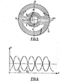
- Each winding is formed on one or two faces of the carrier disc. It consists of a strip of conductive metal (copper) deposited on the face or faces wound in turns according to the arrangement illustrated in FIG. 5.
- Each support 31, 32, 41, 42 is constituted by an electrical and non-magnetic insulating material, for example bakelite.
- This support carries a strip of conductive metal constituting the winding and pressed on said support. The whole of the winding and of the associated support be not very realized according to the technology of printed circuits.
- each primary conductive winding arranged on a primary disc consists, on one side, of two sub-windings with nested turns each extending over a half-crown and, on the on the other side, two sub-windings with overlapping turns each extending over a half-crown.
- the sub-windings arranged on one side are connected so that the direction of the current is reversed from one to the other (clockwise for an observer looking at the upper winding - opposite direction for the winding inferior). In this way a sub-winding occupying a half-crown creates a north pole and the sub-winding occupying the other half-crown creates a south pole.
- each sub-winding forms circular arcs extending from the periphery towards the center of the disc and on the other side each sub-winding forms circular arcs extending from the center towards the periphery.
- the under-winding of the front face ends at B where it crosses the disc and forms an under-winding of the rear face.
- the winding crosses the disc and constitutes the second sub-winding of the avatn face.
- the circuit crosses the disc to form the second sub-winding of the rear face.
- the primary windings 61, 62 formed on the two discs 31, 32 are connected in series.
- the secondary windings 81, 82 of the secondary disks 41 and 42 have a configuration identical to that of the primary windings 61 and 62 formed on the disks 31 and 32.
- the primary and secondary windings can have the same number of turns.
- the rotor 2 is integral with two rotating plates 21 and 22 which each have a non-circular shape.
- Each frame 21 or 22 has a contour constituting two lobes which are limited by circular arcs 211 and 221 centered on the axis of the rotor and are formed by two notches.
- the two lobes of the armature 21 are symmetrical with respect to a straight line V I concurrent with the axis of the rotor.
- the two lobes of the armature 22 are symmetrical with respect to a straight line V 2 concurrent with the axis of the rotor.
- the two plates 21 and 22 are mounted so that their axes of symmetry VI and V 2 are orthogonal.
- the two frames 21 and 22 are made of ferromagnetic material. As an indication, they can be made of soft ferrite so as to avoid losses by hysteresis and by eddy currents.
- each frame 21 or 22 is mounted between a primary disc 31 or 32 and a secondary disc 41 or 42.
- the two primary discs 31 and 32 are arranged on either side of the central cylinder head 12 to which they are attached.
- the disks secondary 41 and 42 are arranged beyond the frames 21 and 22 and are attached to the side cylinder heads 13. Air gaps are formed between each frame 21 or 22 and the discs 31, 41 or 32, ⁇ 2.
- the primary and secondary discs are placed so that the axes of their poles are suitably offset.
- each secondary disc 41 or 42 is placed near a primary disc 31 or 32.
- the rotating plates 21 and 22 are placed so as to frame the secondary discs 41 and 42.
- the plates 21 and 22 are separated from the secondary discs by air gaps.
- Each primary disc 31 or 32 creates, by the associated winding 61 or 62, an alternating magnetic field.
- the reluctance of the magnetic circuit varies with the rotation of the armature in a sinusoidal fashion around a mean value. For one half it is represented by curve 51 in solid lines in FIG. 6. For the other half it is represented by curve 52 in dashed lines in FIG. 6.
- the inductance of the primary circuit is therefore constant whatever the position of the armatures 21 or 22.
- the current in the primary windings is sinusoidal.
- the primary windings 61, 62 are calibrated so that the axis ⁇ (axis passing through the poles) merges with the axis PP 'relative to which the angles are marked in the direction trigonometric.
- the secondary winding 81 of the first half of the resolver is wedged in S 1 S '1 to ⁇ / 4 forward relative to PP'.
- the secondary winding 82 of the second half of the resolver is wedged in S 2 S'2 to ⁇ / 4 behind with respect to PP '.
- the armature 21 occupies the position OV 1 (corresponding to the axis V I ) at ⁇ / 8 forward on OP
- the armature 22 then occupies the position OV 2 (corresponding to the axis V 2 ) at ⁇ / 8 in front of Ox perpendicular to OP.
- the coupling is then maximum for the first half of the resolver (minimum reluctance).
- the coupling is minimal (maximum reluctance) when the armature of this half of the resolver is offset by ⁇ / 2 relative to the position of the maximum coupling.
- the two secondaries work empty and the voltage across their terminals is equal to the electromotive force.
- the voltages e i and e 2 at the terminals of the secondary illustrated in FIG. 8 represent an amplitude modulation of the carrier frequency of the primary.
- sinusoids of period 2 ⁇ / p are obtained, phase shifted by ⁇ / 2 p giving cos P 0 and sin p ⁇ , p being the number of poles and ⁇ the positioning angle of the rotor.
Landscapes
- Physics & Mathematics (AREA)
- General Physics & Mathematics (AREA)
- Engineering & Computer Science (AREA)
- Power Engineering (AREA)
- Transmission And Conversion Of Sensor Element Output (AREA)
Applications Claiming Priority (2)
| Application Number | Priority Date | Filing Date | Title |
|---|---|---|---|
| FR8511337 | 1985-07-24 | ||
| FR8511337A FR2585464A1 (fr) | 1985-07-24 | 1985-07-24 | Resolveur pour reperer la position angulaire d'un organe tournant |
Publications (1)
| Publication Number | Publication Date |
|---|---|
| EP0210927A1 true EP0210927A1 (de) | 1987-02-04 |
Family
ID=9321614
Family Applications (1)
| Application Number | Title | Priority Date | Filing Date |
|---|---|---|---|
| EP86401665A Withdrawn EP0210927A1 (de) | 1985-07-24 | 1986-07-24 | Resolver zur Bestimmung des Positionswinkels eines drehenden Organs |
Country Status (2)
| Country | Link |
|---|---|
| EP (1) | EP0210927A1 (de) |
| FR (1) | FR2585464A1 (de) |
Cited By (8)
| Publication number | Priority date | Publication date | Assignee | Title |
|---|---|---|---|---|
| EP0510367A1 (de) * | 1991-04-26 | 1992-10-28 | Mehnert, Walter, Dr. | Induktiver Stellungsgeber |
| EP0522941A1 (de) * | 1991-07-11 | 1993-01-13 | Gec Alsthom Sa | Einrichtung zur Messung der Winkellage eines Rotors in bezüglich eines Stators |
| FR2680242A1 (fr) * | 1991-08-09 | 1993-02-12 | Alsthom Gec | Capteur reluctant homopolaire. |
| US5475302A (en) * | 1991-08-16 | 1995-12-12 | Walter Mehnert | Inductive pick-up for producing a signal representing the relative positions of two mutually movable bodies |
| EP0802398A1 (de) * | 1994-12-27 | 1997-10-22 | Tamagawa Seiki Kabushiki Kaisha | Geber zur Erfassung der Winkelstellung mit variabler Reluktanz |
| DE4213866B4 (de) * | 1991-04-26 | 2004-01-22 | Papst Licensing Gmbh & Co. Kg | Sensor für Drehbewegungen |
| US20120065840A1 (en) * | 2009-04-17 | 2012-03-15 | Volvo Construction Equipment Ab | Vehicle and method for operating a vehicle |
| CN119853389A (zh) * | 2024-12-18 | 2025-04-18 | 南京航空航天大学 | 一种轴向磁路的空心杯环形绕组磁阻式旋转变压器 |
Citations (4)
| Publication number | Priority date | Publication date | Assignee | Title |
|---|---|---|---|---|
| US2964716A (en) * | 1957-07-29 | 1960-12-13 | United Aircraft Corp | Displacement-to-frequency transducer |
| US3732553A (en) * | 1971-04-16 | 1973-05-08 | Spearhead Inc | Capacitive pick-off transducer |
| FR2381284A1 (fr) * | 1977-02-16 | 1978-09-15 | Aga Ab | Indicateur de position electromecanique |
| FR2529406A1 (fr) * | 1982-06-23 | 1983-12-30 | Labo Electronique Physique | Rotor plan realise en technologie couches epaisses |
-
1985
- 1985-07-24 FR FR8511337A patent/FR2585464A1/fr active Pending
-
1986
- 1986-07-24 EP EP86401665A patent/EP0210927A1/de not_active Withdrawn
Patent Citations (4)
| Publication number | Priority date | Publication date | Assignee | Title |
|---|---|---|---|---|
| US2964716A (en) * | 1957-07-29 | 1960-12-13 | United Aircraft Corp | Displacement-to-frequency transducer |
| US3732553A (en) * | 1971-04-16 | 1973-05-08 | Spearhead Inc | Capacitive pick-off transducer |
| FR2381284A1 (fr) * | 1977-02-16 | 1978-09-15 | Aga Ab | Indicateur de position electromecanique |
| FR2529406A1 (fr) * | 1982-06-23 | 1983-12-30 | Labo Electronique Physique | Rotor plan realise en technologie couches epaisses |
Cited By (13)
| Publication number | Priority date | Publication date | Assignee | Title |
|---|---|---|---|---|
| DE4213866B4 (de) * | 1991-04-26 | 2004-01-22 | Papst Licensing Gmbh & Co. Kg | Sensor für Drehbewegungen |
| US5323109A (en) * | 1991-04-26 | 1994-06-21 | Walter Mehnert | Inductive position indicator for monitoring the relative positions of two mutually movable bodies |
| EP0510367A1 (de) * | 1991-04-26 | 1992-10-28 | Mehnert, Walter, Dr. | Induktiver Stellungsgeber |
| EP0522941A1 (de) * | 1991-07-11 | 1993-01-13 | Gec Alsthom Sa | Einrichtung zur Messung der Winkellage eines Rotors in bezüglich eines Stators |
| FR2679026A1 (fr) * | 1991-07-11 | 1993-01-15 | Alsthom Gec | Dispositif pour la mesure de la position angulaire d'un rotor par rapport a un stator. |
| US5300884A (en) * | 1991-07-11 | 1994-04-05 | Gec Alsthom Sa | Position sensing apparatus for measuring the angular position of a rotor relative to a stator having a plurality of teeth with excitation windings and plural phase reception windings |
| FR2680242A1 (fr) * | 1991-08-09 | 1993-02-12 | Alsthom Gec | Capteur reluctant homopolaire. |
| EP0527673A1 (de) * | 1991-08-09 | 1993-02-17 | Gec Alsthom Sa | Homopolarer veränderlicher Reluktanzgeber |
| US5475302A (en) * | 1991-08-16 | 1995-12-12 | Walter Mehnert | Inductive pick-up for producing a signal representing the relative positions of two mutually movable bodies |
| EP0802398A1 (de) * | 1994-12-27 | 1997-10-22 | Tamagawa Seiki Kabushiki Kaisha | Geber zur Erfassung der Winkelstellung mit variabler Reluktanz |
| US20120065840A1 (en) * | 2009-04-17 | 2012-03-15 | Volvo Construction Equipment Ab | Vehicle and method for operating a vehicle |
| US8694204B2 (en) * | 2009-04-17 | 2014-04-08 | Volvo Construction Equipment Ab | Vehicle and method for operating a vehicle |
| CN119853389A (zh) * | 2024-12-18 | 2025-04-18 | 南京航空航天大学 | 一种轴向磁路的空心杯环形绕组磁阻式旋转变压器 |
Also Published As
| Publication number | Publication date |
|---|---|
| FR2585464A1 (fr) | 1987-01-30 |
Similar Documents
| Publication | Publication Date | Title |
|---|---|---|
| EP0889576B1 (de) | Linearmotor | |
| EP0522941B1 (de) | Einrichtung zur Messung der Winkellage eines Rotors in bezüglich eines Stators | |
| EP0429625B1 (de) | Einphasiges elektromagnetisches betätigungsgerät mit geringem raumbedarf | |
| FR2530889A1 (fr) | Moteur electrique a courant continu sans collecteur | |
| WO1983002042A1 (fr) | Moteur pas a pas electrique | |
| FR2498026A1 (fr) | Moteur electrique sans commutateur ayant des poles magnetiques secondaires | |
| EP0171483A1 (de) | Elektromechanischer Umwandler | |
| EP0210927A1 (de) | Resolver zur Bestimmung des Positionswinkels eines drehenden Organs | |
| CA2294109A1 (fr) | Procede de bobinage en deux plans d'encoche pour une machine electrique tournante | |
| EP0312464B1 (de) | Elektrische Maschine insbesondere mit radialen Luftspalten | |
| EP0500431B1 (de) | Winkelgeber, insbesondere für drehende Maschinen mit sehr hoher Laufgeschwindigkeit | |
| EP0527673B1 (de) | Homopolarer veränderlicher Reluktanzgeber | |
| EP4218121B1 (de) | N-phasige elektrische maschine | |
| EP0321332B1 (de) | Elektrischer Motor mit hohem Wirkungsgrad und schwacher Momentschwingung | |
| FR2526605A1 (fr) | Servomoteur electrique a commande capacitive | |
| EP0559504A1 (de) | Elektromagnetisches Lager | |
| WO2022248221A1 (fr) | Capteur de position inductif symétrique | |
| EP0591514B1 (de) | Rotor/stator für spannungsmodulation für schleiferlosen elektromotor | |
| JP2562042B2 (ja) | ブラシレスd.c.モータ用インダクタンス型センサ | |
| FR2631702A1 (fr) | Dispositif de mesure de dephasage angulaire et application a un couplemetre | |
| EP1351372A1 (de) | Induktiver Winkelgeber des Typs Synchroresolver | |
| WO1982001252A1 (en) | D.c.generator type non-contact speed sensing device | |
| BE1023490B1 (fr) | Moteur électrique | |
| FR2745125A1 (fr) | Structure d'enroulements pour faire fonctionner un moteur a deux phases a partir d'une source triphasee | |
| FR2631178A1 (fr) | Dispositif analogique pour l'autopilotage d'une machine electrique et machine munie d'un tel dispositif |
Legal Events
| Date | Code | Title | Description |
|---|---|---|---|
| PUAI | Public reference made under article 153(3) epc to a published international application that has entered the european phase |
Free format text: ORIGINAL CODE: 0009012 |
|
| AK | Designated contracting states |
Kind code of ref document: A1 Designated state(s): DE GB IT |
|
| STAA | Information on the status of an ep patent application or granted ep patent |
Free format text: STATUS: THE APPLICATION IS DEEMED TO BE WITHDRAWN |
|
| 18D | Application deemed to be withdrawn |
Effective date: 19871006 |
|
| RIN1 | Information on inventor provided before grant (corrected) |
Inventor name: LALANGUE, PIERRE Inventor name: BANON, LOUIS |