EP0210936B1 - Drehbarer Umschalter mit axial verschiebbarem Kegelküken - Google Patents
Drehbarer Umschalter mit axial verschiebbarem Kegelküken Download PDFInfo
- Publication number
- EP0210936B1 EP0210936B1 EP86420201A EP86420201A EP0210936B1 EP 0210936 B1 EP0210936 B1 EP 0210936B1 EP 86420201 A EP86420201 A EP 86420201A EP 86420201 A EP86420201 A EP 86420201A EP 0210936 B1 EP0210936 B1 EP 0210936B1
- Authority
- EP
- European Patent Office
- Prior art keywords
- control member
- axis
- plug
- fluids
- switching device
- Prior art date
- Legal status (The legal status is an assumption and is not a legal conclusion. Google has not performed a legal analysis and makes no representation as to the accuracy of the status listed.)
- Expired
Links
- 239000012530 fluid Substances 0.000 claims description 55
- 230000007246 mechanism Effects 0.000 claims description 18
- 238000005192 partition Methods 0.000 claims description 14
- 239000007788 liquid Substances 0.000 claims description 12
- 238000007789 sealing Methods 0.000 claims description 12
- 238000006073 displacement reaction Methods 0.000 claims description 9
- 238000004891 communication Methods 0.000 claims description 4
- 229920001971 elastomer Polymers 0.000 claims description 4
- 239000000806 elastomer Substances 0.000 claims description 4
- 230000002427 irreversible effect Effects 0.000 claims description 4
- 238000002156 mixing Methods 0.000 claims description 4
- 238000013459 approach Methods 0.000 claims description 3
- 230000008859 change Effects 0.000 claims description 3
- 230000000694 effects Effects 0.000 claims description 3
- 230000009471 action Effects 0.000 claims description 2
- 230000002829 reductive effect Effects 0.000 claims description 2
- 208000031968 Cadaver Diseases 0.000 description 10
- 229910052751 metal Inorganic materials 0.000 description 9
- 239000002184 metal Substances 0.000 description 9
- 238000009826 distribution Methods 0.000 description 7
- 238000003780 insertion Methods 0.000 description 7
- 230000037431 insertion Effects 0.000 description 7
- 238000005406 washing Methods 0.000 description 5
- 238000000576 coating method Methods 0.000 description 4
- HEMHJVSKTPXQMS-UHFFFAOYSA-M Sodium hydroxide Chemical compound [OH-].[Na+] HEMHJVSKTPXQMS-UHFFFAOYSA-M 0.000 description 3
- 239000011248 coating agent Substances 0.000 description 3
- 238000009434 installation Methods 0.000 description 3
- 238000003754 machining Methods 0.000 description 3
- 238000004519 manufacturing process Methods 0.000 description 3
- 238000000034 method Methods 0.000 description 3
- 230000008569 process Effects 0.000 description 3
- 239000007787 solid Substances 0.000 description 3
- 239000000725 suspension Substances 0.000 description 3
- 238000003466 welding Methods 0.000 description 3
- 230000008901 benefit Effects 0.000 description 2
- 230000005465 channeling Effects 0.000 description 2
- 238000010276 construction Methods 0.000 description 2
- 238000010586 diagram Methods 0.000 description 2
- 239000000463 material Substances 0.000 description 2
- 239000000203 mixture Substances 0.000 description 2
- 230000002441 reversible effect Effects 0.000 description 2
- 238000010008 shearing Methods 0.000 description 2
- 125000006850 spacer group Chemical group 0.000 description 2
- 239000000126 substance Substances 0.000 description 2
- 238000012546 transfer Methods 0.000 description 2
- MXRIRQGCELJRSN-UHFFFAOYSA-N O.O.O.[Al] Chemical compound O.O.O.[Al] MXRIRQGCELJRSN-UHFFFAOYSA-N 0.000 description 1
- 229910000831 Steel Inorganic materials 0.000 description 1
- 239000003082 abrasive agent Substances 0.000 description 1
- PNEYBMLMFCGWSK-UHFFFAOYSA-N aluminium oxide Inorganic materials [O-2].[O-2].[O-2].[Al+3].[Al+3] PNEYBMLMFCGWSK-UHFFFAOYSA-N 0.000 description 1
- ANBBXQWFNXMHLD-UHFFFAOYSA-N aluminum;sodium;oxygen(2-) Chemical compound [O-2].[O-2].[Na+].[Al+3] ANBBXQWFNXMHLD-UHFFFAOYSA-N 0.000 description 1
- 229910001570 bauxite Inorganic materials 0.000 description 1
- 230000015572 biosynthetic process Effects 0.000 description 1
- 238000004140 cleaning Methods 0.000 description 1
- 230000007547 defect Effects 0.000 description 1
- 230000000994 depressogenic effect Effects 0.000 description 1
- 238000013461 design Methods 0.000 description 1
- 238000001514 detection method Methods 0.000 description 1
- 230000006866 deterioration Effects 0.000 description 1
- 230000010339 dilation Effects 0.000 description 1
- 238000005516 engineering process Methods 0.000 description 1
- 235000021183 entrée Nutrition 0.000 description 1
- 238000000605 extraction Methods 0.000 description 1
- -1 ferrous metals Chemical class 0.000 description 1
- 238000005304 joining Methods 0.000 description 1
- 230000000670 limiting effect Effects 0.000 description 1
- 230000001050 lubricating effect Effects 0.000 description 1
- 238000005461 lubrication Methods 0.000 description 1
- 238000012423 maintenance Methods 0.000 description 1
- 238000005259 measurement Methods 0.000 description 1
- 230000036961 partial effect Effects 0.000 description 1
- 239000002245 particle Substances 0.000 description 1
- 238000003825 pressing Methods 0.000 description 1
- 238000000926 separation method Methods 0.000 description 1
- 239000011734 sodium Substances 0.000 description 1
- 229910001388 sodium aluminate Inorganic materials 0.000 description 1
- 235000011121 sodium hydroxide Nutrition 0.000 description 1
- 239000010959 steel Substances 0.000 description 1
- 230000001052 transient effect Effects 0.000 description 1
- 238000011144 upstream manufacturing Methods 0.000 description 1
- 210000003462 vein Anatomy 0.000 description 1
- 238000012800 visualization Methods 0.000 description 1
Images





Classifications
-
- F—MECHANICAL ENGINEERING; LIGHTING; HEATING; WEAPONS; BLASTING
- F16—ENGINEERING ELEMENTS AND UNITS; GENERAL MEASURES FOR PRODUCING AND MAINTAINING EFFECTIVE FUNCTIONING OF MACHINES OR INSTALLATIONS; THERMAL INSULATION IN GENERAL
- F16K—VALVES; TAPS; COCKS; ACTUATING-FLOATS; DEVICES FOR VENTING OR AERATING
- F16K11/00—Multiple-way valves, e.g. mixing valves; Pipe fittings incorporating such valves
- F16K11/02—Multiple-way valves, e.g. mixing valves; Pipe fittings incorporating such valves with all movable sealing faces moving as one unit
- F16K11/08—Multiple-way valves, e.g. mixing valves; Pipe fittings incorporating such valves with all movable sealing faces moving as one unit comprising only taps or cocks
- F16K11/083—Multiple-way valves, e.g. mixing valves; Pipe fittings incorporating such valves with all movable sealing faces moving as one unit comprising only taps or cocks with tapered plug
-
- F—MECHANICAL ENGINEERING; LIGHTING; HEATING; WEAPONS; BLASTING
- F28—HEAT EXCHANGE IN GENERAL
- F28G—CLEANING OF INTERNAL OR EXTERNAL SURFACES OF HEAT-EXCHANGE OR HEAT-TRANSFER CONDUITS, e.g. WATER TUBES OR BOILERS
- F28G1/00—Non-rotary, e.g. reciprocated, appliances
- F28G1/12—Fluid-propelled scrapers, bullets, or like solid bodies
- F28G1/125—Fluid-propelled scrapers, bullets, or like solid bodies forced back and forth by means of flow reversal
-
- Y—GENERAL TAGGING OF NEW TECHNOLOGICAL DEVELOPMENTS; GENERAL TAGGING OF CROSS-SECTIONAL TECHNOLOGIES SPANNING OVER SEVERAL SECTIONS OF THE IPC; TECHNICAL SUBJECTS COVERED BY FORMER USPC CROSS-REFERENCE ART COLLECTIONS [XRACs] AND DIGESTS
- Y10—TECHNICAL SUBJECTS COVERED BY FORMER USPC
- Y10T—TECHNICAL SUBJECTS COVERED BY FORMER US CLASSIFICATION
- Y10T137/00—Fluid handling
- Y10T137/4238—With cleaner, lubrication added to fluid or liquid sealing at valve interface
- Y10T137/4358—Liquid supplied at valve interface
-
- Y—GENERAL TAGGING OF NEW TECHNOLOGICAL DEVELOPMENTS; GENERAL TAGGING OF CROSS-SECTIONAL TECHNOLOGIES SPANNING OVER SEVERAL SECTIONS OF THE IPC; TECHNICAL SUBJECTS COVERED BY FORMER USPC CROSS-REFERENCE ART COLLECTIONS [XRACs] AND DIGESTS
- Y10—TECHNICAL SUBJECTS COVERED BY FORMER USPC
- Y10T—TECHNICAL SUBJECTS COVERED BY FORMER US CLASSIFICATION
- Y10T137/00—Fluid handling
- Y10T137/5762—With leakage or drip collecting
-
- Y—GENERAL TAGGING OF NEW TECHNOLOGICAL DEVELOPMENTS; GENERAL TAGGING OF CROSS-SECTIONAL TECHNOLOGIES SPANNING OVER SEVERAL SECTIONS OF THE IPC; TECHNICAL SUBJECTS COVERED BY FORMER USPC CROSS-REFERENCE ART COLLECTIONS [XRACs] AND DIGESTS
- Y10—TECHNICAL SUBJECTS COVERED BY FORMER USPC
- Y10T—TECHNICAL SUBJECTS COVERED BY FORMER US CLASSIFICATION
- Y10T137/00—Fluid handling
- Y10T137/8593—Systems
- Y10T137/86493—Multi-way valve unit
- Y10T137/86863—Rotary valve unit
- Y10T137/86871—Plug
Definitions
- the invention relates to a permutator on which the rotation of the plug, allowing the change of the distribution, is done after the plug has been raised to be released from the body so as to require only a low operating torque and not risk destroying the seals when the body openings pass.
- This permutator relates to the technical field of taps, valves and distributors.
- shutters such as solid joints, taps, valves, distributors, etc. are generally used. of some of these shutters and the technological requirements of the devices served may necessitate the prior cessation of the circulation of the fluid in the affected pipes.
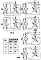
- Figures 1 to 2 relate to the prior art. They give the distribution diagram by obturators such as taps or valves on a tubular exchanger accepting large pressure differences and where it is necessary to swap fluids A and B in the exchanger without changing the direction of circulation. .
- FIGS. 3, 4 and 5 which also refer to the prior art show a distribution diagram by rotary distributors on a plate heat exchanger, in which the pressure difference tolerated on either side of the plates is lower than the operating pressure. This means that one side of the plate, whatever it is, cannot be fed if the other side is not too.
- the torque necessary for the operation of the movable member is all the higher the larger it is, the more the fluid which passes through has no lubricating quality but on the contrary a tendency to the formation of deposits, and also that the time elapsed between two consecutive maneuvers is longer.
- this couple multiplies by the number of matches.
- Ball valve devices are known. They lead to lower operating torques than cylindrical or conical bushels, but a spherical bushel in a necessarily cylindrical housing of the body of the distributor reveals dead zones where particles in suspension in the transported liquid accumulate if the latter contains it and when, in addition, this liquid is scaling or clogging, the maneuvering of the plug becomes difficult and sometimes impossible if means for cleaning these dead zones have not been provided.
- sealing can be done by metal-to-metal contact or by an integral coating of the plug or the body. Mas it could just as well be carried out by particular joints placed around the openings arranged in the bushel, by or transits the fluid to pass from one to the other of the tubes of the body.
- Document US-A 4 286 625 thus describes a conical plug permutator whose sealing between the permutator body and the plug is ensured by deformable seals placed in retaining grooves situated at the periphery of the partition and upper plates. and lower than the bushel. Furthermore, a mechanism ensures the displacement of the plug along a vertical axis as well as its rotation about this same vertical axis allowing the correct insertion and positioning of the plug relative to the pipes of the permutator body.
- Permutator the whole of the device which makes it possible to invert, to "permute” the fluids in the circuits of the apparatus or the apparatuses which it supplies, or the direction the direction of circulation of the fluids inside the device which it supplies or both simultaneously.
- Boisseau the mobile part which by its rotation ensures the permutation, the distribution of fluids.
- Body the envelope inside which the plug is placed and jointly allows the plug to make the intercommunication seals. It comprises the various inlet and outlet pipes for the fluids distributed according to the position of the plug.
- Channels the input / output pairs presented by the permutator on a stage in the different valve positions.
- Orientation the number of possible positions for a bushel revolution. To each of them correspond paths, different from each other.
- Distribution symbolic representation of the routes per floor. It can be in “L” in “T” or in “X” with 2 ways 3 ways or 4 ways.
- Window opening arranged in the plug to constitute the channel allowing the transfer of the fluid from one tubing to the other of the body.
- Sealing and leakage control all the seals equipping the plug, seals of appropriate shape to ensure sealing around each window and allow visualization of external leaks and intercommunications.
- Control mechanism the device maintained on a console and allowing the maneuvering of the plug and the adjustment.
- Console metal frame integral with the body on which the valve control mechanism is arranged.
- the object of the invention is a permutator making it possible to very significantly improve the longevity of the deformable joints and to ensure a permanent and instantaneous control of the tightness of these joints as well as the evacuation of the liquid in the event of leakage without risk.
- mixing with the products of the neighboring compartments and this thanks, on the one hand, to a means of controlling and adjusting the deformation of the seals thus reducing the shearing effects consecutive to excessive and repeated crushing forces of the seals elastomers, and on the other hand to an appropriate shape of the seals making it possible both to detect a leaking fault and to evacuate the leaking liquid as well as to rinse the surfaces of the seals in order to eliminate any deposits of solids.
- the seal constitutes by its form a seal with respect to the lower and upper zones of the body, seal which is interrupted on short portions on the outer periphery of the plates itself provided with notches to form the continuity of the channel between the lower and upper zones, for the evacuation of leaks and rinsing liquid to the outside of the body by a tap at the low point.
- each stage of the body comprises four pipes arranged at 90 ° cooperating with the four windows of the corresponding stage of the bushel, the two stages of the bushel being separated between them by a plate arranged perpendicular to the axis of rotation.
- the axes of pipes of one stage form an angle of 45 ° with the axes of the pipes of the other stage.
- the plug comprises, on the periphery of the upper and lower plates, on the periphery of each separation plate between stages, and on the ends of the internal partitions, separating the separate spaces for circulation of the fluids, a seal in elastomer disposed in a groove.
- ferrous metals are perfectly suitable.
- This body comprises a plurality of pipes (11), those located on the same plane constituting the inlets and outlets of the fluids passing through a stage; the two levels of tubing (12) and (12A) (in FIG. 6) show that this permutator has two stages.
- the pipes (11) of the second stage (12A) are offset by 45 ° with respect to those of the first stage (12). In the case shown, these pipes have flanges (14) for connection to the pipes.
- the body at its lower part, on the small diameter side of the cone, is provided with a bottom which can be welded (15); the upper part of the body, large diameter side has a flange (16) receiving a cover (17).
- the console (18) On this cover, held at the body flange by a series of bolts, is fixed the console (18) which supports the whole of the control mechanism (19) plug which will be described later.
- the plug located inside the body, is not visible in this figure 6. it is connected to the control mechanism via the axis (20).
- the axis (20) passes through the cover (17) by a tight seal (21).
- the lower bottom (15) comprises a tube (22) provided with a tap (23) controlled by an actuator (24) open to allow the detection of leaks.
- the bottom bottom has a flap (25) which appears in the figure (21).
- a tap (23 A) for washing the interior of the permutator after changing the orientation of the plug (26).
- the permutator is supported by feet (13).
- Figure 7 shows a top view of the permutator, we see the pipes (11) and their flanges (14), the upper cover (17) the console (18) supporting the control mechanism (19).
- Figure 8 is a section of the apparatus passing through the median plane AA above the tubes (11); the valve wall (26) is positioned at (27) to establish two tracks 28A 28B and 29A 29B.
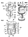
- Figures 9, 10 and 11 show schematically the valve for a 2-stage permutator of 4 channels according to the representation of Figure 6.
- it consists of an upper plate (30), an intermediate plate (31) and a lower plate (32).
- the plates are connected to each other by flat partitions (33).
- the operating control axis (20) of the plug (26) is positioned and fixed by a flange (34), integrated in the upper plate; the lower plate receives an extension (35) which, with the operating axis (20) will keep the plug centered in the body during the maneuvers which are most often done without stopping the currents of fluids.
- a conduit (36) passing through the interior of the plug allows the evacuation of the washing liquid introduced to the upper part of the body by the tap (23A) discharged by the tap (23) placed on the bottom (15) (FIG. 6)
- the plug can be made of welded sheet steel, the quality of which will be chosen according to the physico-chemical requirements of the product being transported.
- Figure 10 shows in its upper part a plate (30) cut by a plane passing through its axis of revolution.
- a plate consists of two sheet metal discs (37) and a cylindrical shell (38) connecting these two sheet metal discs.
- the diameter of the ferrule (38) is smaller than the outside diameter of the discs (37), this in order to arrange at the periphery of the plate a rectangular groove (39) of large dimensions in which the seal will be placed.
- the partition (33) consists of two sheet metal plates (40) connected to each other by spacers (41). As for the plate, the spacers (41) are fixed by welding back the side edges of the sheets (40) to form a rectangular groove large area (42) in which will be placed a double seal (47) ( Figure 12).
- FIG. 10 shows the composition of the plug, the different elements of which are then connected by welding while respecting the relative position of the partitions indicated in FIGS. 10 and 11.
- Figure 11 shows the plug (26) in its overall design from the elements that compose it, plates (30) and (31) and (32) partitions (33).
- the advantage of this bar is twofold: it interconnects the two stages of a stage to improve the mechanical strength of the assembled bushel and it also receives a seal (47) which will keep clean on the body the joint surface not used for a given orientation of the plug (figure 16B).
- the disc elements (37) constituting the plates which intercept the rectilinear grooves (42) presented by the partitions (33) and the bars (43) are cut at (45) to the profile of the groove (42) to obtain continuity in the grooves, which will allow the joining of the joints at the connections.
- the plug is taken on a machine tool to obtain the correct taper on the different discs (37), on the edges of the partition sheets (40) and on the bars (43).
- the circular and rectilinear grooves are also machined to receive the seal in the best conditions. It is at this point that the disc elements (46) disappear.
- the outer discs (37) of the plates (30) and (32) are notched at (46) to allow passage to possible leaks and to the washing liquid introduced by the tap (13A).
- the periphery of the plates and the lateral ends of the partitions are inscribed in a cone of revolution delimiting the plug.
- the free or empty space of the cone of revolution inscribed in the bushel, delimited by the plates at the bottom and at the top and by the lateral ends of the partition constitute the "window" (50) in the bushel, window around which it will be necessary to obtain a seal.
- the plates (30), (31), (32), the partitions (33) of great thickness which make up the plug (26) and the bars (43) have at the outer periphery large grooves of rectangular section, circular grooves ( 39) on the plates and straight lines on the bars (43) and the partitions (33). They communicate with each other to receive a joint (47) in the shape of a solid U ( Figure 12) joined to the connections and adhered to the interior walls of the grooves.
- Each end (51, 53) of the branches of the U formed by the seal provides a particular seal to each window of the plug, the part of the seal located between the two branches of the U constitutes a space (55) channeling outwards any leak caused by a defect on one of the ends of the branches of the U.
- the branches of U located on the side of the end of the bushel are removed locally (66) to allow the channeling of any leak to the outside ( Figure 16A).
- Figure 12 shows in the grooves such as (39) or (42) arranged in the plug the U-shaped profile of the seal (47) particularly studied for this application.
- the adhesion of the seal (47) on the three faces (48 A, B, C) of the groove gives it very good resistance to pressure differences when it passes, released from the body, in front of the body openings while fluid currents have remained established.
- the double span of the joint gives a particular seal to each of the tracks of a stage.
- the bearing (51) establishes the seal on the track (52), the bearing (53) establishes the seal on the track (54). If a leak appears on the bearing surface (51) or on the bearing surface (53), it travels through the channel (55) which has the joint between these two bearing surfaces and through the notches (66A), towards the lower part of the body from which it is discharged through the tap (23) ( Figure 16A).
- FIG. 13 shows two limiting arrangements of the seal (47) belonging for example to the intermediate plate (31), with respect to the pipes (11) of the stages (12) and (12A) and of the body (10).
- Position (58) corresponds to the insertion of the plug into the body for zero crushing of the joint
- position (59) corresponds to the lower limit fixed for the insertion of the joint once crushed; the difference (60) between these two positions depends on the dimensioning of the pipes, their between axis (61) and the width of the joint. For tubing of 250 mm for example, with a joint width of 65 mm the value of this gap (60) is 80 mm. It thus allows fairly wide tolerances on the production of parts and makes it possible to compensate for the sag that the joints would take over time.
- Figure 14 and the values which appear there show that, taking into account the machining tolerances required on the bore of the body (10) (more or less 0.1 mm) and on the gasket seats of the plug (more or less 0.2mm) the dimensional deviations on the spokes are plus or minus 0.15mm.
- measurements carried out on a prototype apparatus led us to fix at 1 mm the average crushing of the joint, which amounts to saying that the local crushing of the joint can be located in borderline cases between 0.85 and 1 , 15 mm.
- Figure 15 shows the seal (47) materialized by a point in position (58) of Figure 13.
- FIG. 16A gives an external view of the vessel (26) equipped with its seals (47).
- the "black” part represents the staves, like (51) and (53); the hatched part, the channel (55) located between the spans.
- the external bearing surface of the plate seal (32) is suppressed locally at (66) so that the possible leak on one of the bearing surfaces of the joint reaches the lower zone (67) of the body connected to the atmosphere by the tap (23) allowing thus to visualize the leaks.
- the same cutout (66) is made on the outer surface of the plate (30) to allow the washing liquid introduced into the upper zone (67A) through the tap (23A) to reach through the channels (55) the lower zone (67).
- the plug (26) is again taken from the machine tool to be machined conically with a fairly wide tolerance, the bearing surfaces of the seal protruding from the metal parts of the grooves having been machined first of all. suitable value to ensure that the seal is crushed without risk of the plug metal coming into contact with the inside of the body.
- the mechanism must provide the plug, with a reduced effort, a rotational movement of 90 ° in one direction, then in the other to be able to return to the initial position, and for example an axial movement of 46 mm to effortlessly move the bushel and then to push it 34 mm into the body to crush the points of 1 mm with a force which can be significant, and provide an axial force to unlock the joints greater than the driving force.
- the device must also allow the setting of the insertion of the plug taking into account the manufacturing tolerances and the conservation of the mechanical properties of the joint, setting with a capacity of 80 mm.
- the system must be irreversible so that it is not necessary to maintain on the plug, during the operation of the permutator, the force to overcome the hydraulic thrust.
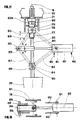
- FIG. 17 represents the system giving the axial movement of descent and lifting of the plug.
- a nut (78) also threaded comprising two axes or trunnions (79) diametrically opposed on which are articulated by one of their ends of the twin rods (80) (the figure is only one).
- these links (80) are articulated on the axes or pins (81) of a straight hydraulic cylinder (82).
- On these same pins (81) are articulated other links (83) of the same length as the links (80).
- the other end of the rods (83) is articulated on the trunnion axes (84) of a nut (85) free to rotate but positioned on the axis (20) by two stops (86) belonging to the shaft.
- a similar system is arranged on the other side of the axis (20) with twin links (87) (88) of the same length, different from the length of the links (80) and (83). These links are coupled to two pins (89) belonging to the particular yoke (90) of the jack (82).
- the entire mobile system is supported by the pins (79) and (84), the quadrilateral formed by the rods will deform under the action of the hydraulic cylinder, to modify the distance between the pins (81) and (89), there will correspond a variation of the center distance of the pins (79) and (84); as the pin (79) is positioned by the nut (76) on the sleeve (71) only the pin (84) will move vertically, driving the control pin (20) via the nut (85) and stops on the axis driving the plug (26).
- Figure 18 is a partial section through a plane passing above the cylinder; there are the console (18), the particular yoke (90) of the jack (82). Note the extra length of the axis (89) and the stops (91) on the console (18).
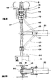
- Figure 19 shows the control mechanism; the cylinder rod being retracted, the poisseau is in the low position pressed into the body, the seals are crushed. It is then noted in FIG. 20 that the ends of the pins (89) press on the stops (91) of the console (18) in order to limit the stroke of the plug.
- the pressure in the cylinder depends on the resistive force along the control axis (20) and on the various frictional forces in the joints negligible compared to the forces necessary for sinking.
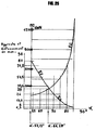
- Ef and Ec respectively show the evolution of the approach (Et) for between 53.13 ° and 66.20 ° and the evolution of the crushing (Ec) of the joint, in mm for a between 66.20 ° and 90 °.
- FIG. 17 clearly shows that the jack (82) supplied with (95) works on the rod side to achieve the insertion of the plug.
- the jack supplied in (96) will provide FC with a greater value than at the time of sinking, generally double, because in the jacks commonly used the section of the rod is substantially equal to half of the piston section.
- FIG. 17 shows the system giving the rotational movement.
- the plug (26) is raised by the system which has been illustrated in FIG. 17, the seals (47) are no longer in contact with the internal wall of the body (10).
- valves (23) and (23A) are closed because the fluid streams have not been cut off on the pipes (11).
- the movable part of the actuator imparts its rotational movement to the sleeve (71) inside which slides the control axis (20) driven in rotation by the sliding key (72).
- the sheath (71) has a stop (73) positioning it longitudinally on the console (18).
- FIG 22 shows the position of these limit switches (75).
- Figures 23 and 24 show a variant of the solution of Figure 21 in which the actuator is a straight vein (76) acting on the connecting rod (74) belonging to the sleeve (71). The stroke is limited by the stops (75) integral with the console (18).
- the position of the crank (74) or an index placed on the barrel (71) makes it possible to know on which of the two possible orientations the bushel is located.
- a two-way four-way permutator 350 mm in diameter, designed for flows close to 1000 m 3 / h, commissioned more recently, ensured to date faultless service and perfect operation.
Landscapes
- Engineering & Computer Science (AREA)
- General Engineering & Computer Science (AREA)
- Mechanical Engineering (AREA)
- Chemical & Material Sciences (AREA)
- Combustion & Propulsion (AREA)
- Multiple-Way Valves (AREA)
- Quick-Acting Or Multi-Walled Pipe Joints (AREA)
- Sliding Valves (AREA)
Claims (10)
Applications Claiming Priority (2)
| Application Number | Priority Date | Filing Date | Title |
|---|---|---|---|
| FR8511918 | 1985-07-26 | ||
| FR8511918A FR2585437B1 (fr) | 1985-07-26 | 1985-07-26 | Permutateur rotatif muni d'un boisseau conique a deplacement axial |
Publications (2)
| Publication Number | Publication Date |
|---|---|
| EP0210936A1 EP0210936A1 (de) | 1987-02-04 |
| EP0210936B1 true EP0210936B1 (de) | 1989-10-18 |
Family
ID=9321953
Family Applications (1)
| Application Number | Title | Priority Date | Filing Date |
|---|---|---|---|
| EP86420201A Expired EP0210936B1 (de) | 1985-07-26 | 1986-07-21 | Drehbarer Umschalter mit axial verschiebbarem Kegelküken |
Country Status (16)
| Country | Link |
|---|---|
| US (1) | US4726391A (de) |
| EP (1) | EP0210936B1 (de) |
| JP (1) | JPS6330670A (de) |
| CN (1) | CN86105734B (de) |
| AU (1) | AU596367B2 (de) |
| BR (1) | BR8603524A (de) |
| CA (1) | CA1296971C (de) |
| DE (1) | DE3666498D1 (de) |
| ES (1) | ES2000377A6 (de) |
| FR (1) | FR2585437B1 (de) |
| GR (1) | GR861882B (de) |
| HU (1) | HU198991B (de) |
| IE (1) | IE57586B1 (de) |
| IN (1) | IN167639B (de) |
| TR (1) | TR22581A (de) |
| YU (1) | YU45021B (de) |
Families Citing this family (11)
| Publication number | Priority date | Publication date | Assignee | Title |
|---|---|---|---|---|
| US5529758A (en) * | 1995-05-15 | 1996-06-25 | Houston; Reagan | Three-bed rotary valve and fume incineration system |
| US6196268B1 (en) | 1999-12-23 | 2001-03-06 | Tm Industrial Supply, Inc. | Rising stem soft seat plug valve |
| US9097354B2 (en) * | 2010-06-14 | 2015-08-04 | Thomas Middleton Semmes | Combined changeover and control valve |
| US9500288B2 (en) * | 2013-11-20 | 2016-11-22 | Thomas Middleton Semmes | Combined control and flow sensing valve |
| CN104006167B (zh) * | 2014-05-30 | 2016-06-15 | 长沙矿冶研究院有限责任公司 | 用于工业窑炉的高温排气阀 |
| CN104315200B (zh) * | 2014-11-07 | 2017-02-01 | 合肥长源液压股份有限公司 | 单阀芯式多路换向阀 |
| FR3041404B1 (fr) * | 2015-09-18 | 2017-09-01 | Valeo Systemes De Controle Moteur | Dispositif de transformation d'un mouvement de pivotement d'un pignon en un mouvement de translation d'un coulisseau et vanne comportant un tel dispositif |
| CN105937635B (zh) * | 2016-06-28 | 2018-04-03 | 中国船舶重工集团公司第七一九研究所 | 一种用于流向切换及流量控制的装置 |
| CN108953673B (zh) * | 2018-08-14 | 2023-08-29 | 珠海格力电器股份有限公司 | 一种多通换向阀和热泵机组 |
| DE102020133047A1 (de) * | 2020-12-10 | 2022-06-15 | Röchling Automotive Se & Co.Kg | Spritzgegossene Kunststoff-Ventilbaugruppe für ein Kraftfahrzeug |
| CN216131420U (zh) * | 2021-05-21 | 2022-03-25 | 华为技术有限公司 | 多通阀、热管理系统和汽车 |
Family Cites Families (10)
| Publication number | Priority date | Publication date | Assignee | Title |
|---|---|---|---|---|
| CA476623A (en) * | 1951-09-04 | Annicq Joseph | Cocks with rotary plugs | |
| US2078231A (en) * | 1934-07-26 | 1937-04-27 | Morgan Smith S Co | Valve |
| US2153885A (en) * | 1935-07-06 | 1939-04-11 | Chapman Valve Mfg Co | Valve apparatus |
| FR1280109A (fr) * | 1960-11-18 | 1961-12-29 | Const Aero Navales | Robinet à voies multiples |
| FR1433455A (fr) * | 1965-02-16 | 1966-04-01 | Commissariat Energie Atomique | Vanne à quatre voies à double mouvement |
| US3908697A (en) * | 1973-10-30 | 1975-09-30 | Polymer Machinery Corp | Rotary fluid valve |
| US4150694A (en) * | 1977-07-27 | 1979-04-24 | Fluid Measurement Systems, Inc. | Rotary plug valve |
| DE2842451A1 (de) * | 1978-09-29 | 1980-04-17 | Drath & Schrader | Ein- oder mehrfachdreiweghahn |
| US4286625A (en) * | 1979-04-18 | 1981-09-01 | Daniel Industries, Inc. | Four-way plug valve |
| DE3102384C2 (de) * | 1981-01-24 | 1986-07-24 | Bühler-Miag GmbH, 3300 Braunschweig | Rohrweiche für pneumatische Förderanlagen zum Fördern pulverigen oder körnigen Gutes |
-
1985
- 1985-07-26 FR FR8511918A patent/FR2585437B1/fr not_active Expired
-
1986
- 1986-07-15 US US06/885,655 patent/US4726391A/en not_active Expired - Fee Related
- 1986-07-18 GR GR861882A patent/GR861882B/el unknown
- 1986-07-21 IN IN578/MAS/86A patent/IN167639B/en unknown
- 1986-07-21 DE DE8686420201T patent/DE3666498D1/de not_active Expired
- 1986-07-21 EP EP86420201A patent/EP0210936B1/de not_active Expired
- 1986-07-21 HU HU862981A patent/HU198991B/hu not_active IP Right Cessation
- 1986-07-23 JP JP61173513A patent/JPS6330670A/ja active Pending
- 1986-07-24 YU YU1327/86A patent/YU45021B/xx unknown
- 1986-07-24 ES ES8600547A patent/ES2000377A6/es not_active Expired
- 1986-07-25 CN CN86105734A patent/CN86105734B/zh not_active Expired
- 1986-07-25 AU AU60561/86A patent/AU596367B2/en not_active Ceased
- 1986-07-25 IE IE1971/86A patent/IE57586B1/en not_active IP Right Cessation
- 1986-07-25 BR BR8603524A patent/BR8603524A/pt not_active IP Right Cessation
- 1986-07-25 CA CA000514709A patent/CA1296971C/fr not_active Expired - Lifetime
-
1987
- 1987-07-21 TR TR31913A patent/TR22581A/xx unknown
Also Published As
| Publication number | Publication date |
|---|---|
| AU6056186A (en) | 1987-01-29 |
| YU132786A (en) | 1989-02-28 |
| IN167639B (de) | 1990-11-24 |
| FR2585437B1 (fr) | 1987-10-16 |
| YU45021B (en) | 1991-06-30 |
| IE57586B1 (en) | 1993-01-13 |
| CN86105734A (zh) | 1987-01-28 |
| BR8603524A (pt) | 1987-03-04 |
| AU596367B2 (en) | 1990-05-03 |
| HUT45595A (en) | 1988-07-28 |
| FR2585437A1 (fr) | 1987-01-30 |
| CN86105734B (zh) | 1988-11-16 |
| DE3666498D1 (en) | 1989-11-23 |
| EP0210936A1 (de) | 1987-02-04 |
| CA1296971C (fr) | 1992-03-10 |
| GR861882B (en) | 1986-11-04 |
| HU198991B (en) | 1989-12-28 |
| JPS6330670A (ja) | 1988-02-09 |
| US4726391A (en) | 1988-02-23 |
| ES2000377A6 (es) | 1988-02-16 |
| TR22581A (tr) | 1987-11-30 |
Similar Documents
| Publication | Publication Date | Title |
|---|---|---|
| EP0210936A1 (de) | Drehbarer Umschalter mit axial verschiebbarem Kegelküken | |
| FR2470321A1 (fr) | Vanne | |
| EP0504032B1 (de) | Redundant Schlussventil | |
| FR2588055A1 (fr) | Vanne a passage direct | |
| CA1261311A (fr) | Dispositif d'obturation pour conduite vehiculant un fluide | |
| FR2901340A1 (fr) | Agencement de distributeur hydraulique sous forme de cartouche | |
| EP3111121B1 (de) | Rotierendes probeentnahmeventil und vorrichtung mit solch einem ventil | |
| EP1155271B1 (de) | Plattenwärmetauscher mit integriertem ventil | |
| WO2020152402A1 (fr) | Système de pompage et installation de refoulement de fluide | |
| FR2514104A1 (fr) | Procede et appareil pour la separation et l'ecoulement separe de gaz et de liquide dans un systeme d'ecoulement | |
| JP5031757B2 (ja) | パイプ分岐装置 | |
| EP2015016A1 (de) | Wärmetauscher für Heizbottich | |
| EP1550534A1 (de) | Flüssigkeitsversorgungsvorrichtung für einen Roboter | |
| FR2756905A1 (fr) | Vanne hydraulique et installation de distribution de liquides equipee de telles vannes | |
| EP0633442A1 (de) | Ringförmiger Sicherheitswärmetauscher für inkompatible Fluide | |
| FR2667116A1 (fr) | Dispositif de pompage d'un fluide polyphasique. | |
| FR2866409A3 (fr) | Raccord femelle pour conduite de fluide | |
| OA20354A (fr) | Système de pompage et installation de refoulement de fluide | |
| EP2306049B1 (de) | Getriebe mit zwei Übersetzungsverhältnissen für Werkzeugmaschinenspindel | |
| FR2869088A1 (fr) | Raccord femelle pour conduite de fluide | |
| FR2889582A1 (fr) | Echangeur tubulaire de chaleur | |
| FR2536824A1 (fr) | Dispositif du type robinet a commande magnetique comportant un clapet pilote | |
| FR2567983A1 (fr) | Garniture pour robinetterie, a intercaler entre deux pieces presentant des canaux a relier de facon etanche, comportant un support avec au moins une ouverture garnie d'un joint avec une epaisseur faible devant l'epaisseur du support | |
| EP2006631A1 (de) | Kollektorflansch für einen Wärmetauscher | |
| EP0172801A1 (de) | Ventil mit parallelen Sitzen |
Legal Events
| Date | Code | Title | Description |
|---|---|---|---|
| PUAI | Public reference made under article 153(3) epc to a published international application that has entered the european phase |
Free format text: ORIGINAL CODE: 0009012 |
|
| AK | Designated contracting states |
Kind code of ref document: A1 Designated state(s): DE GB IT NL |
|
| 17P | Request for examination filed |
Effective date: 19870219 |
|
| 17Q | First examination report despatched |
Effective date: 19871215 |
|
| GRAA | (expected) grant |
Free format text: ORIGINAL CODE: 0009210 |
|
| AK | Designated contracting states |
Kind code of ref document: B1 Designated state(s): DE GB IT NL |
|
| ITF | It: translation for a ep patent filed | ||
| GBT | Gb: translation of ep patent filed (gb section 77(6)(a)/1977) | ||
| REF | Corresponds to: |
Ref document number: 3666498 Country of ref document: DE Date of ref document: 19891123 |
|
| PLBE | No opposition filed within time limit |
Free format text: ORIGINAL CODE: 0009261 |
|
| STAA | Information on the status of an ep patent application or granted ep patent |
Free format text: STATUS: NO OPPOSITION FILED WITHIN TIME LIMIT |
|
| 26N | No opposition filed | ||
| PGFP | Annual fee paid to national office [announced via postgrant information from national office to epo] |
Ref country code: NL Payment date: 19920731 Year of fee payment: 7 |
|
| PG25 | Lapsed in a contracting state [announced via postgrant information from national office to epo] |
Ref country code: NL Effective date: 19940201 |
|
| NLV4 | Nl: lapsed or anulled due to non-payment of the annual fee | ||
| ITTA | It: last paid annual fee | ||
| PGFP | Annual fee paid to national office [announced via postgrant information from national office to epo] |
Ref country code: DE Payment date: 19990622 Year of fee payment: 14 |
|
| PGFP | Annual fee paid to national office [announced via postgrant information from national office to epo] |
Ref country code: GB Payment date: 19990719 Year of fee payment: 14 |
|
| PG25 | Lapsed in a contracting state [announced via postgrant information from national office to epo] |
Ref country code: GB Free format text: LAPSE BECAUSE OF NON-PAYMENT OF DUE FEES Effective date: 20000721 |
|
| GBPC | Gb: european patent ceased through non-payment of renewal fee |
Effective date: 20000721 |
|
| PG25 | Lapsed in a contracting state [announced via postgrant information from national office to epo] |
Ref country code: DE Free format text: LAPSE BECAUSE OF NON-PAYMENT OF DUE FEES Effective date: 20010501 |
|
| PG25 | Lapsed in a contracting state [announced via postgrant information from national office to epo] |
Ref country code: IT Free format text: LAPSE BECAUSE OF NON-PAYMENT OF DUE FEES;WARNING: LAPSES OF ITALIAN PATENTS WITH EFFECTIVE DATE BEFORE 2007 MAY HAVE OCCURRED AT ANY TIME BEFORE 2007. THE CORRECT EFFECTIVE DATE MAY BE DIFFERENT FROM THE ONE RECORDED. Effective date: 20050721 |