EP0210995B1 - Connecteur electrique a boucle fermee - Google Patents
Connecteur electrique a boucle fermee Download PDFInfo
- Publication number
- EP0210995B1 EP0210995B1 EP85905701A EP85905701A EP0210995B1 EP 0210995 B1 EP0210995 B1 EP 0210995B1 EP 85905701 A EP85905701 A EP 85905701A EP 85905701 A EP85905701 A EP 85905701A EP 0210995 B1 EP0210995 B1 EP 0210995B1
- Authority
- EP
- European Patent Office
- Prior art keywords
- connector
- terminals
- shunt means
- housing
- mating
- Prior art date
- Legal status (The legal status is an assumption and is not a legal conclusion. Google has not performed a legal analysis and makes no representation as to the accuracy of the status listed.)
- Expired - Lifetime
Links
- 210000002105 tongue Anatomy 0.000 claims abstract description 24
- 230000013011 mating Effects 0.000 claims abstract description 19
- 230000000295 complement effect Effects 0.000 claims description 11
- 239000002184 metal Substances 0.000 description 5
- 230000003247 decreasing effect Effects 0.000 description 2
- 230000014759 maintenance of location Effects 0.000 description 2
- 230000006835 compression Effects 0.000 description 1
- 238000007906 compression Methods 0.000 description 1
- 230000000717 retained effect Effects 0.000 description 1
Images






Classifications
-
- H—ELECTRICITY
- H01—ELECTRIC ELEMENTS
- H01R—ELECTRICALLY-CONDUCTIVE CONNECTIONS; STRUCTURAL ASSOCIATIONS OF A PLURALITY OF MUTUALLY-INSULATED ELECTRICAL CONNECTING ELEMENTS; COUPLING DEVICES; CURRENT COLLECTORS
- H01R13/00—Details of coupling devices of the kinds covered by groups H01R12/70 or H01R24/00 - H01R33/00
- H01R13/648—Protective earth or shield arrangements on coupling devices, e.g. anti-static shielding
- H01R13/658—High frequency shielding arrangements, e.g. against EMI [Electro-Magnetic Interference] or EMP [Electro-Magnetic Pulse]
- H01R13/6591—Specific features or arrangements of connection of shield to conductive members
- H01R13/65912—Specific features or arrangements of connection of shield to conductive members for shielded multiconductor cable
-
- H—ELECTRICITY
- H01—ELECTRIC ELEMENTS
- H01R—ELECTRICALLY-CONDUCTIVE CONNECTIONS; STRUCTURAL ASSOCIATIONS OF A PLURALITY OF MUTUALLY-INSULATED ELECTRICAL CONNECTING ELEMENTS; COUPLING DEVICES; CURRENT COLLECTORS
- H01R24/00—Two-part coupling devices, or either of their cooperating parts, characterised by their overall structure
- H01R24/84—Hermaphroditic coupling devices
-
- H—ELECTRICITY
- H01—ELECTRIC ELEMENTS
- H01R—ELECTRICALLY-CONDUCTIVE CONNECTIONS; STRUCTURAL ASSOCIATIONS OF A PLURALITY OF MUTUALLY-INSULATED ELECTRICAL CONNECTING ELEMENTS; COUPLING DEVICES; CURRENT COLLECTORS
- H01R13/00—Details of coupling devices of the kinds covered by groups H01R12/70 or H01R24/00 - H01R33/00
- H01R13/02—Contact members
- H01R13/28—Contacts for sliding cooperation with identically-shaped contact, e.g. for hermaphroditic coupling devices
Definitions
- the present invention relates to a hermaphroditic electrical connector having means for connecting selected terminals therein when in unmated condition.
- a hermaphroditic electrical connector of the type comprising an insulating housing having a plurality of conductive terminals mounted at one side thereof, and electrical shunt means therein, said terminals having resilient contact tongues which engage like tongues in a like connector, said shunt means being in shunted relation with said terminals when said connector is in an unmated condition, said shunt means being in unshunted relation with said terminals when said connector is in mating engagement with a complementary connector.
- the connector disclosed in US Patent No. 4449 778 employs shunt bars which are fixed in the housing and have lugs which make contact with resilient contact tongues of the terminals when the connector is in an unmated condition.
- the contact tongues engage like contact tongues in a complementary hermaphroditic connector and thus deform the contact tongues away from the lugs on the shunt bars.
- This arrangement suffers the disadvantage that, in order to have adequate contact pressure between the shunt means and the contact tongues of the terminals, the tongues must be substantially deformed. The additional deformation imposed by like terminals during mating must be quite small, else the tongues be deflected beyond their elastic limit and suffer decreased contact pressure with the shunt means on their return.
- the present invention is characterized in that said shunt means are fixed to a dielectric carrier which is on the opposite side of the housing to the terminals, and which moves relative to said housing in response to mating with and disengagement from a complementary connector, said shunt means engaging portions of said terminals remote from said contact tongues, on disengagement, to interconnect alternate terminals, and said shunt means moves relative to said housing and out of shunted relation with said terminal portions on engagement wioh a complementary connector.
- the portions of the terminals engaged by the shunt means as well as the shunt means are isolated from the mating face of the connector, in a fully enclosed portion of the connector, whereby foreign matter cannot interfere with shunting.
- the contact lugs are disposed freely toward the portions of the terminals engaged thereby at an oblique angle, whereby a wiping action occurs during engagement and disengagement with the complementary hermaphroditic connector.
- the connector of said embodiment also features a strain relief housing molded in two parts connected by a hinge, the halves being hinged through 180 degrees to engage the cable jacket and a ground ferrule on the braid.
- a locking ferrule is screwed onto the housing to achieve a good grip on the cable, only one half of the housing being threaded, whereby alignment problems are eliminated.
- a square flange thereon is inserted through a like-profiled hole in the connector, then tunred through 45 degrees before finishing assembly of the connector to lock the stain relief in place.
- the braided cable shield is dressed back over a split metal ferrule and forced through a circular aperture in the connector shield, whereby the braid is forced radially against the connector shield.
- the braid is thus under controlled force engagement on its entire perimeter, thus assuring a stable low resistance contact and complete shielding.
- the connector 2 of the present invention comprises a mating face 4 where it engages the mating face of a like hermaphroditic connector and an opposed cable receiving face 5 where cable 6 enters for termination.
- the external profile of the connector is quite similar to that of the connector disclosed in U.S. Patent No. 4,449,778 and is defined by a lower cover part 80 having a latch 83, and an upper cover part 110 having a complementary latch 118.
- the housing 20 having terminal support platform 22 to which terminals 10 are fixed is visible in mating face 4 below hood 91 which bridges sidewalls 84 of the lower cover part 80. Plugs 92 in sidewalls cover alternate cable entry points in sidewalls 84.
- FIG. 2 shows the terminal housing 20 with terminals 10 assembled thereto and stuffer 18 poised thereabove.
- Lower shield 65 is stamped and formed metal comprising a base panel 66 having forward contact portion 68 formed integrally therewith, which portion 68 makes contact with a like portion in a like hermaphroditic connector when mated.
- Sidewalls 69 having circular apertures 70 therein, are formed upward from base panel 66 and have wings 64 and resilient tongues 75 formed forwardly thereof for mating with like tongues and wings in a like connector, whereby shielding continuity is achieved. See U.S. Patent Application No. 666,573, where a similar arrangement is disclosed.
- Rearwall 71 is also formed from sidewalls 69 and includes a circular aperture 72.
- the shield 65 is shaped to rest in lower cover part 80, which part is molded in plastic and includes a base panel 82 and sidewalls 84 having square apertures 85 therein and recesses 86 with posts 87 in the tops thereof.
- Rearwall 88 likewise has a square aperture 89 therein angled at 45 degrees as shown and two small apertures 90 which serve a latching function with upper cover part 110.
- a hood 91 bridges the forward ends of sidewalls 84 and likewise serves to latch cover part 110 as will be described.
- the connector is assembled by snapping the shield plugs 92 into apertures 70.
- the plugs 92 are retained by resilient outer fingers 93.
- Each plug 92 also has an inner aperture surrounded by resilient inner fingers 95 which engage a post 98 ( Figure 4) in the center of cover plug 97.
- the lower shield 65 is nested in lower cover part 80, the housing 20 with terminals 10 is nested in the lower shield 65, and the cable 6 with strain relief 120 assembled thereto is inserted through apertures 89, 72.
- the strain relief 120 is molded in two halves 121, 122 which are hinged together on the cable 6 and an outer ferrule 134 is screwed thereto for retention.
- the braided shield 8 is folded back on a split metal ferrule 9 forward of an inside square flange 124 which is profiled to fit neatly through aperture 89 in the lower cover part; the braid 8 is received in aperture 72 and forced against shield 65 uniformly by the radially expansive force of the split ferrule, which will be described more fully in conjunction with Figure 8.
- the strain relief 120 is then rotated through 45 degrees so that the side edges of outside square flange 126 are parallel to the edges of rearwall 88.
- Wires 7 are then dressed into channels 34 in the housing 20 and inserted into wire barrels 11 by stuffer 18.
- the upper cover 110 with upper shield 100 assembled thereto is then assembled to lower cover 80.
- a latch 113 ( Figure 3) on panel portion 112 of upper cover 110 is hooked under hood 91 and rear latches 115 snap into apertures 90 as side flanges 116 are received in recesses 86.
- the lower and upper covers 80, 110 have resiliently hinged latching members 83, 118 respectively which cooperate with like members on a mated connected for retention.
- the housing 20 comprises a forward end 21, a rearward end 22, and a trough 30 lying therebetween.
- a terminal support platform 24 has channels 25 therein which extend from end 21 to trough 30, each channel 25 having upstanding therein a wedge-shaped stop 26 to which a respective terminal 10 is fixed.
- the terminals 10 each comprise a wire barrel 11, a base portion 12, and a resilient torque 14 reversely bent from the base portion 12.
- a tail 16 is stamped from slot 13 in base portion 12. Barrels 11 are received on respective posts 31 in trough 30 while tails 16 extend through apertures 32 ( Figure 3). Wedges 26 are received in slots 13 in an interference fit and lie under tongues 14 to prevent overstress.
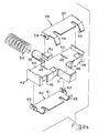
- Shunt assembly 40 comprising a carrier 42 having first shunt bar 56, a second shunt bar 60, and a coil spring 54, is shown poised for reception in the underside of the housing 20.
- carrier 42 has a top surface 44 with slots 45 therein, an opposed bottom surface 46 with similar slots, a forward face 48 with channels 49 therein and an actuator 51 extending centrally thereof, and an opposed rear face 50 having a post 53 extending rearwardly thereof and a guide 52 extending upwardly thereof.
- the first shunt bar 56 has a stamped bridge portion 57 with flanges 58 extending downwardly thereof for interference reception in slots 45 and resilient lugs 59 depending from the forward edge thereof which are aligned with alternate channels 49 in housing 42.
- the second shunt bar 60 likewise has a stamped bridge portion 61 with flanges 62 and resilient lugs 63 depending therefrom, and is received against bottom surface 46 wiht lugs 63 aligned with alternate channels 49.
- the lugs 59, 63 are only performed before assembly to carrier 42, final forming being accomplished against channels 49 after assembling the shunt bars 56, 60 to the carrier 42.
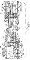
- FIG. 3 is an exploded section which shows the cooperation of all internal parts.
- the housing 20 has a chamber 35 having a forward wall 36 and a rearward wall 37 profiled in the bottom thereof; the shunt assembly is emplaced in chamber 35 so that spring 54 bears against rearwall 37 and resilient lugs 59, 63 bear against respective terminal tails 16, which in turn lie against forward wall 36 of chamber 35, actuator 51 protruding through a channel 29 at the forward end of the chamber.
- the guide 52 rides closely in a channel 33 to prevent cocking of the assembly 40 in operation.
- the lower shield 65 is fitted in lower cover 80 so that post 81 on base panel 82 is received through aperture 67, and serves to position the housing 20 in the connector, post 81 being received in aperture 23 of rear platform 28.
- Figure 4 is a partially sectioned plan view, upper cover removed, showing the strain relief 120 and connection between braided shield 8 and lower shield 65 to best advantage.
- the inner square flange 124 is separated from outer square flange 126 by a cylindrical section 125 which permits rotation in aperture 89 of lower cover 80; the section is taken through laterally opposed corners of aperture 89 so that the retaining corners of flange 124 against rearwall 80 bo not appear.
- Metal ferrule 9 is seated in counterbore 131 of bore 130 in strain relief ferrule 120; the braid 8 is dressed against ferrule 9 to make direct contact with lower shield 65. Note that only ferrule half 121 is threaded, half 122 is not threaded.
- ferrule 120 is depicted as molded; the halves 121, 122 are swung so that protrusions 132 grip the cable 6, the ferrule 134 is threaded home, and the assembly is applied to the rear of the connector as previously described.
- the ferrule 9 is generally tubular and has a seam 107 which permits radial compression thereof.
- the seam 107 comprises a first surface 108 and a generally parallel second surface 109, which surfaces are cut at about 45 degrees to the circumferential tangent they intersect.
- Figure 8A is a partial end view of the ferrule 9 as manufactured, in the unstressed state. The surfaces 108, 109 are in contact and overalp as shown, the sharp edges being most proximate, whereby the braid cannot be caught in seam 107 when dressed.
- Figure 8B shows the ferrule in the radially compressed state, as it would be in Figure 4.
- the surfaces 108, 109 have slid against each other to overlap with the dull edges most proximate, the effective diameter of the ferrule being decreased.
- the ferrule 9 so compressed exerts a uniform radial force on the braid 8 trapped between the ferrule 9 and shield 65 ( Figure 4).
Landscapes
- Details Of Connecting Devices For Male And Female Coupling (AREA)
Abstract
Claims (4)
Applications Claiming Priority (2)
| Application Number | Priority Date | Filing Date | Title |
|---|---|---|---|
| US684233 | 1984-12-20 | ||
| US06/684,233 US4602833A (en) | 1984-12-20 | 1984-12-20 | Closed loop connector |
Publications (2)
| Publication Number | Publication Date |
|---|---|
| EP0210995A1 EP0210995A1 (fr) | 1987-02-25 |
| EP0210995B1 true EP0210995B1 (fr) | 1990-09-26 |
Family
ID=24747235
Family Applications (1)
| Application Number | Title | Priority Date | Filing Date |
|---|---|---|---|
| EP85905701A Expired - Lifetime EP0210995B1 (fr) | 1984-12-20 | 1985-10-31 | Connecteur electrique a boucle fermee |
Country Status (5)
| Country | Link |
|---|---|
| US (1) | US4602833A (fr) |
| EP (1) | EP0210995B1 (fr) |
| JP (1) | JPH0670908B2 (fr) |
| DE (1) | DE3579921D1 (fr) |
| WO (1) | WO1986003894A1 (fr) |
Families Citing this family (31)
| Publication number | Priority date | Publication date | Assignee | Title |
|---|---|---|---|---|
| US4682836A (en) * | 1985-10-07 | 1987-07-28 | Thomas & Betts Corporation | Electrical connector and cable termination apparatus therefor |
| US4737118A (en) * | 1985-12-20 | 1988-04-12 | Amp Incorporated | Hermaphroditic flat cable connector |
| US4666231A (en) * | 1986-06-26 | 1987-05-19 | Amp Incorporated | Switching coaxial connector |
| US4859201A (en) * | 1986-12-22 | 1989-08-22 | Amp Incorporated | Data communications outlet |
| ES1004786Y (es) * | 1986-12-22 | 1989-04-01 | Amp Incorporated | Un conectador electrico. |
| US4832614A (en) * | 1987-12-22 | 1989-05-23 | Amp Incorporated | Electrical connector with improved shunt |
| US4990094A (en) * | 1987-12-21 | 1991-02-05 | Amp Incorporated | Data distribution panel |
| US4952170A (en) * | 1989-02-23 | 1990-08-28 | Amp Incorporated | Shunted connector assembly and interdigitated shunt assembly therefor |
| US5030121A (en) * | 1990-02-13 | 1991-07-09 | Thomas & Betts Corporation | Electrical connector with contact wiping action |
| US5052940A (en) * | 1990-05-11 | 1991-10-01 | Rit-Rad Interconnection Technologies Ltd. | Hermaphroditic self-shorting electrical connector |
| US5190464A (en) * | 1991-03-29 | 1993-03-02 | Chian Chyun Enterprise Co. Ltd. | Shielded electrical connector with contact shunting arrangement |
| US5328380A (en) * | 1992-06-26 | 1994-07-12 | Porta Systems Corp. | Electrical connector |
| IL106494A (en) * | 1992-09-08 | 1996-10-31 | Whitaker Corp | Shielded data connector |
| US5405268A (en) * | 1993-02-04 | 1995-04-11 | Thomas & Betts Corporation | Vertically aligned electrical connector components |
| US5376021A (en) * | 1993-02-05 | 1994-12-27 | Thomas & Betts Corporation | Enhanced performance data connector |
| US5346405A (en) * | 1993-05-04 | 1994-09-13 | The Whitaker Corporation | Shunted connector assembly and shunt assembly therefor |
| US5593311A (en) * | 1993-07-14 | 1997-01-14 | Thomas & Betts Corporation | Shielded compact data connector |
| CA2130216C (fr) * | 1993-08-30 | 2004-10-26 | Brent B. Lybrand | Connecteur compact blinde pour la transmission de donnees |
| US5538440A (en) * | 1993-11-17 | 1996-07-23 | Thomas & Betts Corporation | Electrical connector having a conductor holding block |
| US5514007A (en) * | 1994-05-04 | 1996-05-07 | Thomas & Betts Corporation | Data connector strain relief assembly |
| US5538434A (en) * | 1994-05-18 | 1996-07-23 | The Whitaker Corporation | Electrical connector with integral shorting assembly |
| US5558529A (en) * | 1994-08-02 | 1996-09-24 | Burndy Corporation | Electrical connector with shunt system |
| GB2293285A (en) * | 1994-09-16 | 1996-03-20 | Oxford Magnet Tech | Electrical connectors |
| US5540602A (en) * | 1995-06-30 | 1996-07-30 | The Whitaker Company | Terminal junction block having commoned bus members |
| US6036534A (en) * | 1997-02-26 | 2000-03-14 | 3M Innovative Properties Company | Low profile shunt connector |
| US6328601B1 (en) * | 1998-01-15 | 2001-12-11 | The Siemon Company | Enhanced performance telecommunications connector |
| GB2436897A (en) * | 2006-04-03 | 2007-10-10 | Brand Rex Ltd | Stepped electrical connector |
| DE202006012687U1 (de) * | 2006-08-17 | 2007-12-27 | Weidmüller Interface GmbH & Co. KG | Modulares Steckverbindersystem |
| ES2355224B1 (es) * | 2010-10-26 | 2012-02-07 | Tyco Electronics Amp España, S.A. | Caja de carcasa de alojamiento de un conector de comunicaciones. |
| US8430689B2 (en) * | 2011-07-22 | 2013-04-30 | Tyco Electronics Corporation | Electrical connector |
| US9551483B1 (en) * | 2015-07-01 | 2017-01-24 | Tyco Electronics Corporation | Multiple cable disconnect |
Family Cites Families (13)
| Publication number | Priority date | Publication date | Assignee | Title |
|---|---|---|---|---|
| US2639341A (en) * | 1948-04-27 | 1953-05-19 | George G Truax | Safety battery connector switch |
| GB1203852A (en) * | 1967-05-19 | 1970-09-03 | Bolkow Gmbh | Electric plug connection |
| US3512043A (en) * | 1967-11-09 | 1970-05-12 | Asea Ab | Means for short-circuiting the secondary circuit of a current transformer |
| US3845450A (en) * | 1972-12-26 | 1974-10-29 | Bendix Corp | Underwater electrical connector |
| US3903385A (en) * | 1973-10-25 | 1975-09-02 | E Advanced Packaging Inc Sa | Shorting bar switch in electrical connector biasing assembly |
| US4230386A (en) * | 1979-01-12 | 1980-10-28 | Farnworth Ivan A | Self locking safety socket |
| JPS5699652A (en) * | 1980-01-10 | 1981-08-11 | Mitsuboshi Belting Ltd | Aligning apparatus for bead wire |
| US4460234A (en) * | 1981-09-18 | 1984-07-17 | Virginia Patent Development Corporation | Double-ended modular jack |
| JPS58113279U (ja) * | 1982-01-27 | 1983-08-02 | 星電器製造株式会社 | ジヤツク |
| IE55318B1 (en) * | 1982-12-22 | 1990-08-01 | Amp Inc | Shunt-protected electrical connector |
| US4501459A (en) * | 1982-12-22 | 1985-02-26 | Amp Incorporated | Electrical connector |
| US4449778A (en) * | 1982-12-22 | 1984-05-22 | Amp Incorporated | Shielded electrical connector |
| US4582376A (en) * | 1984-04-09 | 1986-04-15 | Amp Incorporated | Shorting bar having wiping action |
-
1984
- 1984-12-20 US US06/684,233 patent/US4602833A/en not_active Expired - Lifetime
-
1985
- 1985-10-31 DE DE8585905701T patent/DE3579921D1/de not_active Expired - Fee Related
- 1985-10-31 EP EP85905701A patent/EP0210995B1/fr not_active Expired - Lifetime
- 1985-10-31 JP JP60505021A patent/JPH0670908B2/ja not_active Expired - Lifetime
- 1985-10-31 WO PCT/US1985/002152 patent/WO1986003894A1/fr not_active Ceased
Also Published As
| Publication number | Publication date |
|---|---|
| US4602833A (en) | 1986-07-29 |
| WO1986003894A1 (fr) | 1986-07-03 |
| EP0210995A1 (fr) | 1987-02-25 |
| JPS62501246A (ja) | 1987-05-14 |
| DE3579921D1 (de) | 1990-10-31 |
| JPH0670908B2 (ja) | 1994-09-07 |
Similar Documents
| Publication | Publication Date | Title |
|---|---|---|
| US4602833A (en) | Closed loop connector | |
| US4744769A (en) | Closed loop connector | |
| EP0738029B1 (fr) | Connecteur électrique avec verrouillage | |
| US4653825A (en) | Shielded electrical connector assembly | |
| US5586911A (en) | Shielding data connector | |
| CA1213954A (fr) | Connecteur a saisie absolue des broches | |
| US4606596A (en) | Stress relief apparatus for electrical connectors | |
| US6257914B1 (en) | Electrical connector with integral latch and strain relief device | |
| US4786260A (en) | Electrical cable assembly | |
| US5934942A (en) | Shielded electrical connector assembly | |
| US4963102A (en) | Electrical connector of the hermaphroditic type | |
| US5435744A (en) | Sliding boot assembly for electrical connector | |
| US3950070A (en) | Flat flexible cable terminal and electrical interconnection system | |
| US4460230A (en) | Connector hood constructions | |
| US5273453A (en) | Electrical connector with positive latch | |
| JPH0782892B2 (ja) | ドロワコネクター | |
| CN113555740A (zh) | 插头连接器 | |
| CN215645260U (zh) | 线缆组件以及插头连接器 | |
| US5372520A (en) | Shielded data connector | |
| US3763458A (en) | Terminal retaining connector block | |
| CA1107366A (fr) | Connecteur electrique | |
| US5571030A (en) | Protected connector assembly having double ended shorting clip | |
| US5154630A (en) | Plug connector assembly | |
| US6203359B1 (en) | Insulation displacement connection connector | |
| US4349239A (en) | Low mating force connector for connecting groups of wires |
Legal Events
| Date | Code | Title | Description |
|---|---|---|---|
| PUAI | Public reference made under article 153(3) epc to a published international application that has entered the european phase |
Free format text: ORIGINAL CODE: 0009012 |
|
| 17P | Request for examination filed |
Effective date: 19860818 |
|
| AK | Designated contracting states |
Kind code of ref document: A1 Designated state(s): DE FR GB IT |
|
| 17Q | First examination report despatched |
Effective date: 19880321 |
|
| RAP3 | Party data changed (applicant data changed or rights of an application transferred) |
Owner name: AMP INCORPORATED (A NEW JERSEY CORPORATION) |
|
| RAP1 | Party data changed (applicant data changed or rights of an application transferred) |
Owner name: AMP INCORPORATED |
|
| GRAA | (expected) grant |
Free format text: ORIGINAL CODE: 0009210 |
|
| AK | Designated contracting states |
Kind code of ref document: B1 Designated state(s): DE FR GB IT |
|
| ITF | It: translation for a ep patent filed | ||
| ET | Fr: translation filed | ||
| REF | Corresponds to: |
Ref document number: 3579921 Country of ref document: DE Date of ref document: 19901031 |
|
| PLBE | No opposition filed within time limit |
Free format text: ORIGINAL CODE: 0009261 |
|
| STAA | Information on the status of an ep patent application or granted ep patent |
Free format text: STATUS: NO OPPOSITION FILED WITHIN TIME LIMIT |
|
| 26N | No opposition filed | ||
| ITTA | It: last paid annual fee | ||
| REG | Reference to a national code |
Ref country code: GB Ref legal event code: 732E |
|
| PGFP | Annual fee paid to national office [announced via postgrant information from national office to epo] |
Ref country code: GB Payment date: 20010914 Year of fee payment: 17 |
|
| PGFP | Annual fee paid to national office [announced via postgrant information from national office to epo] |
Ref country code: FR Payment date: 20011005 Year of fee payment: 17 |
|
| PGFP | Annual fee paid to national office [announced via postgrant information from national office to epo] |
Ref country code: DE Payment date: 20011030 Year of fee payment: 17 |
|
| REG | Reference to a national code |
Ref country code: GB Ref legal event code: IF02 |
|
| PG25 | Lapsed in a contracting state [announced via postgrant information from national office to epo] |
Ref country code: GB Free format text: LAPSE BECAUSE OF NON-PAYMENT OF DUE FEES Effective date: 20021031 |
|
| PG25 | Lapsed in a contracting state [announced via postgrant information from national office to epo] |
Ref country code: DE Free format text: LAPSE BECAUSE OF NON-PAYMENT OF DUE FEES Effective date: 20030501 |
|
| GBPC | Gb: european patent ceased through non-payment of renewal fee | ||
| PG25 | Lapsed in a contracting state [announced via postgrant information from national office to epo] |
Ref country code: FR Free format text: LAPSE BECAUSE OF NON-PAYMENT OF DUE FEES Effective date: 20030630 |
|
| REG | Reference to a national code |
Ref country code: FR Ref legal event code: ST |