EP0211276A2 - Machine pour le travail du sol - Google Patents
Machine pour le travail du sol Download PDFInfo
- Publication number
- EP0211276A2 EP0211276A2 EP86109591A EP86109591A EP0211276A2 EP 0211276 A2 EP0211276 A2 EP 0211276A2 EP 86109591 A EP86109591 A EP 86109591A EP 86109591 A EP86109591 A EP 86109591A EP 0211276 A2 EP0211276 A2 EP 0211276A2
- Authority
- EP
- European Patent Office
- Prior art keywords
- tool
- receiving opening
- machine according
- soil cultivation
- tools
- Prior art date
- Legal status (The legal status is an assumption and is not a legal conclusion. Google has not performed a legal analysis and makes no representation as to the accuracy of the status listed.)
- Granted
Links
Images


Classifications
-
- A—HUMAN NECESSITIES
- A01—AGRICULTURE; FORESTRY; ANIMAL HUSBANDRY; HUNTING; TRAPPING; FISHING
- A01B—SOIL WORKING IN AGRICULTURE OR FORESTRY; PARTS, DETAILS, OR ACCESSORIES OF AGRICULTURAL MACHINES OR IMPLEMENTS, IN GENERAL
- A01B33/00—Tilling implements with rotary driven tools, e.g. in combination with fertiliser distributors or seeders, with grubbing chains, with sloping axles, with driven discs
- A01B33/08—Tools; Details, e.g. adaptations of transmissions or gearings
- A01B33/14—Attaching the tools to the rotating shaft, e.g. resiliently or flexibly-attached tools
- A01B33/146—Attaching the tools to the rotating shaft, e.g. resiliently or flexibly-attached tools the rotating shaft being oriented vertically or steeply inclined
Definitions
- the invention relates to a tillage machine according to the preamble of claim 1.
- a tillage machine is known from DE-GM 82 13 540.
- the tools in this tillage machine are each fastened to the tool rotor with the aid of two screw bolts.
- the disadvantage of this type of fastening is that on the one hand relatively large and high-strength bolts must be used.
- the bolts must be tightened with very large forces so that the tools remain securely attached to the tool gyro even under the most difficult operating conditions. It is very complex and time-consuming when the tools have to be replaced.
- Replacing the tools in the known machine takes a very long time, especially to loosen the screws and tighten them again. Furthermore, it is practically impossible, especially on the field or for the farmer alone with the help of on-board tools, to replace tines on the field.
- the invention has for its object to significantly simplify and facilitate the replacement of tools, so that the tools can be replaced in a very short time.
- the AMAZONE rotary cultivator brochure with the print reference "D 574 * 2.84" already discloses a fastening for straight tines which are inserted into a receiving opening pointing downwards, so that there is a positive connection between the tools and the receiving openings of the tool rotors.
- the tools are held in the receiving openings by a safety bolt.
- webs directed downward to form the receiving openings are located on the underside of the tool gyroscope and that a plate connecting at least two webs is welded onto the underside of the webs.
- the invention provides that a countersink is arranged on the top of the tool gyroscope in the region of the bores in which the bolts are arranged. It is provided according to the invention that the bolts are sunk on the top of the tool gyroscope. This means that stones cannot get caught between the bolts and the gearbox housing and therefore cannot damage the gearbox housing.
- the countersink is designed as a hexagon. This means that hexagon screws can also be arranged in the recess. This is particularly advantageous if the bolts are to be secured with a screw nut. The bolts cannot therefore twist.
- the recess formed as a hexagon or other forms of recess also has the advantage that the bolts cannot rotate. This prevents wear.
- the invention provides that the securing parts or quick-release fasteners of the bolts are arranged in a protected manner on the underside of the tool gyroscope. This avoids damage to the safety parts during rough use of the machine.
- a protective screen preferably standing, is arranged on the underside of the tool gyroscope, at least in the direction of rotation of the tool gyroscope, in front of the bolts.
- the tool rotors having a round cross section that the diameter of the tool rotors corresponds approximately to the distance between the upper outer parts of the tools.
- a particularly good protected arrangement of the fastening part of the tools is achieved in that the tool rotors have a narrow circumferential ring which at least partially covers the fastening part of the tool.
- the receiving opening at least in its outer radial area from the center of the receiving opening in the tangential direction, has a substantially greater height than the height of the fastening parts of the tools .
- the fastening part can rotate by a certain amount over a certain range of its length within the receiving opening about an axis lying perpendicular to the axis of rotation of the tool gyroscope.
- the tillage tool hits stones that are in the ground or are stuck, so that the tillage tool can move backwards by a certain amount by the fastening part being able to twist inside the receiving opening like a torsion spring.
- integrally formed fastening part is connected to the processing part of the tillage tool results in a surprisingly simple manner in a very effective and simple suspension option for the tillage tool, when it encounters stones or other obstacles located in the ground.
- the tillage tool itself is designed as a spring element and the larger receiving opening located in the outer radial area of the receiving opening achieves an extremely effective suspension for the tool rotors that is insensitive to external influences.
- the invention provides that the receiving openings in the tool rotors for the fastening parts extend at least approximately to the center of the tool rotator and that the fastening parts extend at least approximately to Extend the center of the tool top into the receiving openings.
- a sufficiently secure attachment of the tillage tool to the tool gyroscope is achieved, since the attachment part is held in its receptacle opening at its outer end over a sufficiently long path.
- the receiving opening then has approximately a cross section which corresponds to the cross section of the fastening part.
- the receiving opening in its area closest to the center of the tool gyroscope has a cross-section which corresponds at least approximately to the cross-section of the fastening parts of the tools, and that the receiving openings are above all at a distance from the center of the tool gyroscope in the tangential direction increase gradually or at least approximately continuously in the lateral areas of the receiving openings.
- the upper and lower surfaces of the receiving openings run obliquely upwards or downwards from the center of the receiving opening. This results in a very simple design of the receiving openings, which is mirror-symmetrical to the central longitudinal axis, so that the tool gyroscope with the receiving opening can be produced in a simple manner as a forged part. It is then provided that the receiving opening is closed and formed by a base plate welded to the tool gyroscope.
- the receiving opening has an approximately X-shaped cross section, this cross section extending from the outside inwards in the radial direction and at a distance from the axis of rotation of the tool gyroscope into one cross-section at least approximately corresponds to the cross-section of the inner part of the fastening part of the tool.
- a further improvement is achieved in a manner according to the invention in that in the middle of the receiving opening there is a web extending in the radial direction on the lower and the upper side of the receiving opening, the vertical distance between the upper and the lower web being reduced corresponds approximately to the height of the fastening part.
- the invention provides that: - the fastening part on its side facing away from the tool has a recess which corresponds to the contour of the hub of the tool gyroscope, that the receiving opening extends to the center of the tool gyroscope to the side of the hub of the tool gyroscope, and that the tongues of the fastening part formed by the recess are laterally the Extend the hub to approximately the center of the tool top.
- the invention provides, in order to achieve a secure mounting or holding possibility for the fastening part while at the same time having a sufficiently long twisting path of the fastening part of the tillage tool, that the larger cross-section of the receiving opening does not exceed at least half the length of the receiving opening of the fastening part Fifth of the length of the receiving opening or the fastening part extends.
- German patent 28 49 869 already discloses a tillage machine with a plurality of tool rotors which are arranged next to one another in a row running transversely to the direction of travel and have downward-facing tillage tools. These tillage tools are fastened to a spring package lying horizontally and extending transversely to the axis of rotation of the tool gyroscope, so that these tillage tools when they strike the ground Know any stones or other obstacles to move backwards by turning the spring assembly to which the tools are attached.
- This arrangement of the tillage tools on flat spring assemblies is structurally very complex and expensive. Furthermore, the tillage tools can only be replaced in a time-consuming and complex manner if the tillage tools are worn out.
- the invention provides, so that no damage to the tines or the machine occurs even under the most extreme conditions, that the receiving opening for the fastening part of the tool extends at least approximately over the entire diameter of the tool gyroscope, and that the receiving opening extends from the beginning of the fastening part in the direction of the side facing the tool expands continuously on its upper and lower side at least in the lateral areas of the receiving opening.
- This creates an extremely long fastening part which extends practically over the entire width or diameter of the tool gyroscope and which can rotate in the receiving opening practically over the entire length of the receiving opening. This results in a very large alternative for the tillage part of the tillage tine when it hits a stone stuck in the ground.
- the invention provides that the receiving opening extends over at least two thirds of its length X-shaped cross section.
- each tool gyroscope has two receiving openings which are arranged one below the other. In another embodiment, it is provided according to the invention that each tool gyroscope has two receiving openings which are arranged side by side. This creates an extremely compact and flat tool rotor.
- the tillage machine can either be designed as a rotary cultivator or as a rotary harrow.
- the main difference between a rotary cultivator and a rotary harrow is the arrangement of the tools.
- this machine is referred to as a rotary cultivator, but when the tool tips continue to run when viewed in the direction of rotation; i.e. are arranged sluggishly, one speaks of a rotary harrow.
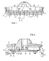
- the tillage machine has the frame 1, in which the tool rotors 2 are arranged next to one another in a row running transversely to the direction of travel.
- the tool rotors 2 are driven by the power take-off of the tractor moving the tillage machine, the respectively adjacent tool rotors 2 rotating in the opposite direction of rotation indicated by the arrow 3 about upright axes.
- the tool rotors 2 are plate-shaped.
- the tools 4 projecting downward are attached to these tool rotors 2.
- the packer roller 6 with its tines 7 arranged on the circumference is arranged behind the tillage machine.
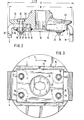
- the tool rotors 2 have receiving openings 8 pointing radially outwards for the respective fastening part 9 of the tools 4.
- the tools 4 each have a processing part 10 which processes and a the soil fastening part 9 angled approximately at right angles to the machining part 10. This fastening part 9 has the two bores 11.
- the tool gyroscope 2 consists of the upper forged part 12, which has a central bore for attachment to a drive shaft of a transmission, not shown, which is arranged in the frame 1, and of the plate 13 welded to the forged part 12.
- the downward webs 15 are each arranged in one piece on the forged part to form the receiving opening 8.
- the plate 13, which connects the four 15 located on the underside is welded on.
- the plate 15 has in its center a large central bore 16 so that the fastening element for securing the tool gyroscope 2 can be arranged on the drive shaft within this central bore 16.
- this plate has two bores 17 in the region of each receiving opening, which are aligned with the respective bores which are arranged in the forged part 12 in the region of the receiving opening. Furthermore, these bores 17 are aligned with the bores 11 in the fastening part 9 of the tools 4 when the fastening part 9 of the tools 4 is inserted into these receiving openings.
- the receiving openings 8 have a somewhat larger cross section than the fastening part 9 of the tool.
- the fastening parts 9 of the tools are easily detachably held in the receiving opening of the tool rotors 2 by the two bolts 18 inserted through the bores 11 and 17.
- the bolts 18 are designed as pins 19 Quick fasteners secured in the holes of the tool gyroscope.
- the bolts 18 are arranged sunk on the top of the tool rotor 2.
- the countersink 20 is designed as a hexagon, so that the hexagon 21 located on the upper side of the pin 18 is arranged in a rotationally fixed manner in the respective bore 17, so that it cannot twist.
- a protective shield 22 is arranged on the underside of the tool gyro in front of the quick-release fasteners 19.
- split pins 19 are also arranged in a recess which could be arranged in the plate 13.
- the tool rotors 2 have a diameter D which corresponds approximately to the distance A between the upper outer parts of the tools 4.
- the tool rotors 2 have the narrow circumferential ring 23. It is thus achieved that there is only a small distance B between the individual tool rotors 2 arranged next to one another, so that no stones can get caught between the individual tool rotors 2 arranged next to one another. Thus, no damage to the tool rotors 2 can occur by jamming stones between them.
- the tool gyro according to FIG. 4 differs from the tool gyroscope according to FIG. 2 only in the design of the securing bolts.
- These securing bolts 24 are designed as screws, the screws being secured on the underside of the tool gyroscope by nuts 25.
- these nuts 25 are as self-locking nuts. Since these locking screws can be designed to be relatively small, these locking screws can be removed in a simple manner by knocking them off with a chisel if the hexagon of the nuts is damaged or ground by touching the ground or by impact from stones. Thus, in this exemplary embodiment too, the tools 4 can be replaced in a simple manner in a very short time.
- the quick-release fasteners have to be removed from the bolts in a simple manner. Since the bolts 18 and 24 are arranged with play in their bores and in the fastening part 9, they can be easily removed without great effort. Since the fastening parts 9 of the tools 4 can be arranged with a certain play in the receiving openings 8 of the tool gyroscope 2, the tools can be pulled out of the receiving openings 8 of the tool gyroscope 2 very easily. The fastening parts of the new tools 4 are then simply inserted from the outside into the receiving opening 8. The tools 2 are then secured by inserting the bolts 18 or 24 into the holes provided in the tool gyroscope 2 and in the fastening part 9 of the tools 4. These bolts 18 or 24 are then secured either by a split pin 19 or by a nut 25. The tools 4 can therefore be exchanged in the shortest possible time without great effort. This exchange work is even carried out by the farmer in the field.
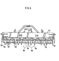
- the tool rotors 102 have the frame 101 in which the tool rotors 102 are arranged next to one another in a row running transversely to the direction of travel.
- the tool gyroscope 102 are from the PTO of the tractor moving the tillage machine is driven, the adjacent tool rotors 102 being driven in the opposite direction of rotation indicated by the arrow 103 and rotating about upright axes.
- the tools 102 are plate-shaped.
- the soil working tools 104 which project downward and are designed as knives or tines, are fastened to these tool rotors 102.
- a side plate 105 is arranged laterally next to the respective outer tool rotors 102, which limits the displacement of the earth to the outside.
- the packer roller 106 with its prongs 107 arranged on the circumference is arranged behind the tillage machine.
- the tool rotors 102 have receiving openings 108 directed radially outward for the respective fastening part 109 of the tillage tools 104.
- the soil cultivation tools 104 each have a cultivation part 110 which cultivates the soil and a fastening part 109 which is angled approximately at right angles to the soil cultivation part 110. This fastening part 109 has a bore 111.
- Each tool gyroscope 102 consists of the upper forged part 112, which has a central bore for attachment to a drive shaft of the gears, not shown, which are arranged in the frame 101, and of the base plate 113 welded to the forged part 112.
- the webs 115 pointing downward are each arranged in one piece on the forged part 112 to form the receiving opening 108.
- the plate 113 which connects the webs to one another, is welded onto the underside of the webs 115.
- the plate 113 has a large central bore 116 in its center, so that inside this central bore 116, the fastening element for securing the tool gyroscope 102 can be arranged on the drive shaft of the tool gyroscope. Furthermore, this plate has in the region of each receiving opening the bore 117 which is aligned with the respective bore which is arranged in the forged part 112 in the region of the receiving opening. Furthermore, this bore 117 is aligned with the respective bore 111 in the fastening part 109 of the tools 104 when the fastening part 109 of the tools 104 is inserted into these receiving openings.
- the receiving openings 108 have a larger cross section than the fastening part 109 of the tillage tool 4.
- the fastening parts 109 of the tools 104 arranged in these receiving openings 108 are arranged with a certain play, so that the tillage tools 104 are arranged in an easily detachable manner in these receiving openings.
- the fastening parts 109 of the tools are held in the receiving opening of the tool gyroscope 102 in an easily detachable manner by the bolts 118 inserted through the bores 111 and 117.
- the bolts 118 are secured in the bores of the tool gyroscope 102 by means of the adjusting locks designed as split pins 119.
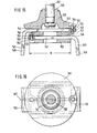
- the receiving opening 108 has in its outer radial region 120, seen in the tangential direction from the center 121 of the receiving opening 108, a substantially greater height E than the height F of the consolidation parts 109 of the tillage tools 104.
- the receiving openings 108 in the tool rotors 102 for the fastening parts 108 each extend to the middle 122 of the tool rotors 102 and the fastening parts 109 of the tillage tools 104 also protrude into the middle 122 of the tool rotors 102 Receiving openings 108 into it.
- the fastening part has, on its side 123 facing away from the tillage part 110, the cutout 124 which corresponds to the contour of the hub 125 of the tool gyroscope 102.
- the tongues 126 of the fastening part 109 formed by the recess 124 extend laterally of the hub 124 to the center 122 of the tool gyroscope 102.
- the larger outer cross section 127 of the receiving opening 108 extends over more than half the length L of the receiving opening 108 or of the fastening part 109, however, not more than four fifths of the length L of the receiving opening 108 or the fastening part 109 of the tillage tool 104.
- the receiving openings 108 in the tool rotors 102 for receiving the fastening part 109 of the tillage tool 104 have a cross section 129 in their area 128 closest to the center 122 of the tool rotator 102, which cross section corresponds at least approximately to the cross section of the fastening parts 109 of the tillage tools 104.
- the receiving opening 108 has a larger cross section 127. This larger cross section 127 of the receiving opening 108 increases from the center 121 of the receiving opening 108 in the tangential direction, especially in the lateral regions of the receiving opening.
- the upper surface 130 of the rear half 131 of the receiving opening 108 runs obliquely upwards approximately from the center 121 of the receiving opening 108, and the lower surface 132 of the front half 133 of the receiving opening 108, as seen in the direction of rotation 103, extends from the center 121 of the receiving opening 108 sloping down. Furthermore, the upper and lower surfaces 130, 132, 134 and 135 of the receiving opening 108 each run obliquely upward or downward from the center 121 of the receiving opening 108.
- the receiving opening 108 points in from the side seen in the radial direction or in the direction of the axis of rotation of the tool gyroscope 102 has an approximately X-shaped cross section 127, this cross section 127 extending from the outside inwards in the radial direction and at a distance from the axis of rotation of the tool gyroscope 102 in an at least approximately the cross section of the inner part 126 of the fastening part 109 of the tool 104 corresponding cross-section 129 passes.
- the webs 136 which each extend in the radial direction.
- the vertical distance between the upper and the lower web 136 corresponds to the height F of the fastening part 109
- the fastening part 109 of the respective tillage tool 104 is supported on these webs 136 and is held by the tongues 126 of the fastening part 109 which extend into the inner cross section 127 in the position shown in solid lines in FIG. 8.
- the fastening part 109 of the tillage tool 104 can twist resiliently within the outer area of the receiving opening 108 due to the X-shaped AusblJJung the outer region of the receiving opening 108 , so that the working part 110 of the tillage tool 104 can pivot into the position 137 shown in dash-dotted lines.
- the groove-shaped depressions 138 are also made by forging.
- the elevations arranged on the fastening part 109 and formed in an elevated manner fit into these depressions 138. This ensures that the tillage tools are in the direction of rotation the tool gyroscope 102 always correctly installed.
- the distance of the depressions 138 from the center of the receiving openings in the left-hand rotating tool rotors can have a different dimension than the distance in the right-hand rotating tool rotors.
- the depressions 138 in the left-hand rotating tool rotors 102 are arranged in mirror image to the two right-hand rotating tool rotors 102.
- the tool rotor 140 according to FIGS. 15 to 17 is arranged on the rotatably driven shaft 141.
- the shaft 141 of the rotary harrow is driven by a gear from the PTO of the tractor pulling the rotary harrow.
- the rotary harrow has a plurality of shafts 141 arranged next to one another in a row running transversely to the direction of travel, to which the tool rotors 140 are fastened.
- the tool rotors 140 are plate-shaped when viewed in plan view.
- the bottom working tools 142 and 143 which are designed as tines and protrude downward, are fastened to these tool rotors 140.
- the tool rotors 140 have receiving openings 144 and 145 directed radially outwards for the respective fastening part 146 and 147 of the tines 142 and 143.
- the tillage tines 142 and 143 each have the obliquely downward machining part 148 and a fastening part 146 and 147 angled approximately at right angles to the machining part 148.
- Each tool gyro 140 consists of the upper forged part 149, which has a central bore 150 for fastening the tool gyro 140 to the drive shaft 141 of the transmission, not shown. Furthermore, this tool gyroscope additionally consists of the base plates 151 and 152 welded to the forged part 149.
- the tool gyroscopes 140 have the tillage tines for each fastening part 146 and 147 142 and 143 the superimposed receiving openings 144 and 145 for the fastening parts 146 and 147 of the tillage tines 142 and 143.
- the receiving openings 144 and 145 for the fastening parts 146 and 147 of the tillage tines 142 and 143 extend over the entire diameter D of the tool rotor 140.
- the fastening parts 146 and 147 have the bore 154.
- a screw bolt 155 is inserted through each of these holes 154.
- This screw bolt 155 is also inserted through the bore 156 located in the tool gyro 140, so that the tools 142 and 143 are each secured and held in the tool gyro 140 by this screw bolt 155.
- the receiving opening 144 and 145 has a cross section corresponding to the fastening part 146 and 147, the beginning of the fastening part each enclosing a small play in these parts of the receiving opening .
- the receiving openings 144 and 145 expand in the direction of the side facing the tillage part 148 on their upper and lower sides in the lateral area of the receiving openings. In the middle of the receiving opening, the receiving openings 144 and 145 are at a distance from one another which corresponds approximately to the height of the fastening part 146 and 147 of the tillage tines 142 and 143, so that the tillage tines 142 and 143 or their fastening parts 146 and 147 have a contact surface.
- the widening in the lateral area of the receiving opening results in an X-shaped cross section of the receiving opening, this continuously widening X-shaped cross section at least overlapping two thirds of the length, which corresponds approximately to the diameter D of the tool gyroscope 140 in the region of the receiving openings.
- the receiving openings 144 and 145 of the tool top 140 are arranged one below the other.
- This type of design of the receiving openings 144 and 145 which has an X-shaped cross-section which widens continuously in the direction of the processing part 148 of the tillage tines 142 and 143, the expansion essentially extending from the beginning of the fastening part in the direction of the tillage part in the side Area as well as extending from the center of the receiving opening to the outside, it is achieved that the fastening part 146 or 147 can rotate resiliently within the receiving opening about the central axis 157 of the respective receiving opening 144 and 145. This allows the machining parts 148 of the. Soil tillage tines 142 and 143 dodge elastically against the direction of travel and spring back into their normal position after crossing the obstacle stuck in the ground.
- the tool gyro 158 according to FIG. 4 differs from the tool gyroscope 140 according to FIGS. 1 to 3 essentially in that the receiving openings 159 and 160 for the fastening parts 161 of the tillage tines 162 are not located one below the other, but in a top view or in the view from are arranged next to one another below in the tool rotor 158.
- the tillage tines 162 are held by the bolts 163 passing through the fastening parts 161 of the tillage tines 162 and the tool rotor 158.
- the receiving openings 159 and 160 for receiving the fastening parts 161 of the tillage tines 162 extend approximately over the entire diameter D of the tool rotor 158
- the receiving opening 159 or 160 widens continuously from the beginning of the fastening part in the direction of the side facing the tillage tine 162 on its upper and lower side from the center line 164 of the receiving opening 159 and 160 in the direction of its lateral areas.
Landscapes
- Life Sciences & Earth Sciences (AREA)
- Engineering & Computer Science (AREA)
- Mechanical Engineering (AREA)
- Soil Sciences (AREA)
- Environmental Sciences (AREA)
- Soil Working Implements (AREA)
Applications Claiming Priority (6)
| Application Number | Priority Date | Filing Date | Title |
|---|---|---|---|
| DE3527580 | 1985-08-01 | ||
| DE19853527580 DE3527580A1 (de) | 1985-08-01 | 1985-08-01 | Bodenbearbeitungsmaschine |
| DE19853543554 DE3543554A1 (de) | 1985-12-10 | 1985-12-10 | Bodenbearbeitungsmaschine |
| DE3543554 | 1985-12-10 | ||
| DE19863622530 DE3622530A1 (de) | 1986-07-04 | 1986-07-04 | Bodenbearbeitungsmaschine |
| DE3622530 | 1986-07-04 |
Publications (3)
| Publication Number | Publication Date |
|---|---|
| EP0211276A2 true EP0211276A2 (fr) | 1987-02-25 |
| EP0211276A3 EP0211276A3 (en) | 1987-08-19 |
| EP0211276B1 EP0211276B1 (fr) | 1989-06-28 |
Family
ID=27193361
Family Applications (1)
| Application Number | Title | Priority Date | Filing Date |
|---|---|---|---|
| EP86109591A Expired EP0211276B1 (fr) | 1985-08-01 | 1986-07-14 | Machine pour le travail du sol |
Country Status (2)
| Country | Link |
|---|---|
| EP (1) | EP0211276B1 (fr) |
| DE (1) | DE3664088D1 (fr) |
Cited By (14)
| Publication number | Priority date | Publication date | Assignee | Title |
|---|---|---|---|---|
| EP0258645A1 (fr) * | 1986-08-29 | 1988-03-09 | Amazonen-Werke H. Dreyer GmbH & Co. KG | Machine pour travailler le sol |
| GB2200826B (en) * | 1986-11-07 | 1991-01-16 | Dowdeswell Eng Co Ltd | Cultivator blade mounting |
| EP0761079A1 (fr) * | 1995-09-01 | 1997-03-12 | Rabewerk GmbH + Co. | Machine pour le travail du sol |
| EP0891688A1 (fr) | 1997-07-18 | 1999-01-20 | Kuhn S.A. | Fixation améliorée et rapide pour outils de travail d'une machine agricole |
| EP0891687A1 (fr) * | 1997-07-18 | 1999-01-20 | Kuhn S.A. | Outil amovible pour machine de travail du sol |
| AT405592B (de) * | 1992-04-02 | 1999-09-27 | Poettinger Ohg Alois | Kreiselegge |
| FR2789542A1 (fr) * | 1999-02-11 | 2000-08-18 | Tiverton Limited | Equipement de herse rotative a dents simples |
| FR2789543A1 (fr) * | 1999-02-11 | 2000-08-18 | Tiverton Limited | Equipement de herse rotative a double dent |
| EP1082889A1 (fr) * | 1999-09-08 | 2001-03-14 | MASCHIO S.p.A. | Système de couplage rapide de dent pour herse rotative |
| FR2802385A1 (fr) * | 1999-12-21 | 2001-06-22 | Eurosystems Spa | Semelle porte-outils pour ensembles de binage et bineuse equipee d'une telle semelle |
| EP1208729A1 (fr) * | 2000-11-24 | 2002-05-29 | F. W. Pettit Limited | Améliorations relatives ou liées aux herses actionnées |
| EP1287728A1 (fr) * | 2001-08-24 | 2003-03-05 | Rabe Agrarsysteme GmbH & Co. KG | Machine pour le travail du sol à dents rotatives |
| EP1419682A1 (fr) * | 2002-11-12 | 2004-05-19 | Frandent di Ezio Bruno | ensemble porte-outils pour une machine de travail du sol et outil pour l'ensemble |
| WO2016199163A1 (fr) * | 2015-06-12 | 2016-12-15 | Tirth Agro Technology Pvt. Ltd. | Mécanisme de montage rapide pour lame de herse à mouvement alternatif |
Family Cites Families (8)
| Publication number | Priority date | Publication date | Assignee | Title |
|---|---|---|---|---|
| NL123530C (fr) * | 1960-04-11 | |||
| DK108324C (da) * | 1965-08-20 | 1967-11-13 | Kongskilde Maskinfabrik As | Bolteforbindelse, navnlig til fastspænding af en harvetand på en bærestang. |
| US3887014A (en) * | 1970-05-19 | 1975-06-03 | Lely Cornelis V D | Soil cultivators |
| NL7007690A (fr) * | 1970-05-28 | 1971-11-30 | ||
| NL7216408A (fr) * | 1972-12-04 | 1974-06-06 | ||
| NL7409705A (nl) * | 1974-07-18 | 1976-01-20 | Lely Nv C Van Der | Grondbewerkingsmachine. |
| FR2310687A1 (fr) * | 1975-05-16 | 1976-12-10 | Anjou Atel Mec | Bride pour le montage d'une dent sur le chassis, notamment pour un instrument de preparation du sol avant semis |
| FR2447134A1 (fr) * | 1979-01-29 | 1980-08-22 | Kuhn Sa | Herse rotative perfectionnee |
-
1986
- 1986-07-14 DE DE8686109591T patent/DE3664088D1/de not_active Expired
- 1986-07-14 EP EP86109591A patent/EP0211276B1/fr not_active Expired
Cited By (17)
| Publication number | Priority date | Publication date | Assignee | Title |
|---|---|---|---|---|
| EP0258645A1 (fr) * | 1986-08-29 | 1988-03-09 | Amazonen-Werke H. Dreyer GmbH & Co. KG | Machine pour travailler le sol |
| GB2200826B (en) * | 1986-11-07 | 1991-01-16 | Dowdeswell Eng Co Ltd | Cultivator blade mounting |
| AT405592B (de) * | 1992-04-02 | 1999-09-27 | Poettinger Ohg Alois | Kreiselegge |
| EP0761079A1 (fr) * | 1995-09-01 | 1997-03-12 | Rabewerk GmbH + Co. | Machine pour le travail du sol |
| EP0891688A1 (fr) | 1997-07-18 | 1999-01-20 | Kuhn S.A. | Fixation améliorée et rapide pour outils de travail d'une machine agricole |
| EP0891687A1 (fr) * | 1997-07-18 | 1999-01-20 | Kuhn S.A. | Outil amovible pour machine de travail du sol |
| FR2766054A1 (fr) * | 1997-07-18 | 1999-01-22 | Kuhn Sa | Outil amovible pour machine de travail du sol |
| FR2789543A1 (fr) * | 1999-02-11 | 2000-08-18 | Tiverton Limited | Equipement de herse rotative a double dent |
| FR2789542A1 (fr) * | 1999-02-11 | 2000-08-18 | Tiverton Limited | Equipement de herse rotative a dents simples |
| EP1082889A1 (fr) * | 1999-09-08 | 2001-03-14 | MASCHIO S.p.A. | Système de couplage rapide de dent pour herse rotative |
| FR2802385A1 (fr) * | 1999-12-21 | 2001-06-22 | Eurosystems Spa | Semelle porte-outils pour ensembles de binage et bineuse equipee d'une telle semelle |
| EP1208729A1 (fr) * | 2000-11-24 | 2002-05-29 | F. W. Pettit Limited | Améliorations relatives ou liées aux herses actionnées |
| EP1287728A1 (fr) * | 2001-08-24 | 2003-03-05 | Rabe Agrarsysteme GmbH & Co. KG | Machine pour le travail du sol à dents rotatives |
| EP1419682A1 (fr) * | 2002-11-12 | 2004-05-19 | Frandent di Ezio Bruno | ensemble porte-outils pour une machine de travail du sol et outil pour l'ensemble |
| WO2016199163A1 (fr) * | 2015-06-12 | 2016-12-15 | Tirth Agro Technology Pvt. Ltd. | Mécanisme de montage rapide pour lame de herse à mouvement alternatif |
| GB2555267A (en) * | 2015-06-12 | 2018-04-25 | Tirth Agro Tech Pvt Ltd | A quick fit mechanism for power harrow blade |
| GB2555267B (en) * | 2015-06-12 | 2021-06-23 | Tirth Agro Tech Pvt Ltd | A quick fit mechanism for power harrow blade |
Also Published As
| Publication number | Publication date |
|---|---|
| DE3664088D1 (en) | 1989-08-03 |
| EP0211276A3 (en) | 1987-08-19 |
| EP0211276B1 (fr) | 1989-06-28 |
Similar Documents
| Publication | Publication Date | Title |
|---|---|---|
| EP0211276B1 (fr) | Machine pour le travail du sol | |
| EP0033950A1 (fr) | Outil pour travailler le sol commandé par un arbre de prise de force | |
| EP0150731B1 (fr) | Outil à main de jardinage pour l'ameublissement du sol | |
| DE7617432U1 (de) | Schlepperbetriebene bodenbearbeitungsmaschine | |
| DE2728656B2 (de) | Erdbearbeitungswerkzeug für Sämaschinen | |
| DE3446312C2 (fr) | ||
| EP0293675B1 (fr) | Dispositif pour le travail du sol | |
| DE2850894C2 (fr) | ||
| CH630225A5 (de) | Kreiselegge. | |
| DE3338284C2 (fr) | ||
| EP0081600B1 (fr) | Herse rotative | |
| DE2833399A1 (de) | Kreiselgrubber | |
| EP0129047B1 (fr) | Machine agricole pour le travail du sol comportant un rotor équipé de dents | |
| DE3409110A1 (de) | Bodenbearbeitungsmaschine, insbesondere kreiselegge | |
| DE2849868C3 (de) | Bodenbearbeitungsmaschine | |
| EP0258645B1 (fr) | Machine pour travailler le sol | |
| DE3854683T2 (de) | Bodenbearbeitungsmaschine. | |
| EP0118868A2 (fr) | Machine pour le travail du sol | |
| DE3543554A1 (de) | Bodenbearbeitungsmaschine | |
| DE9418722U1 (de) | Landwirtschaftliche Bodenbearbeitungsmaschine | |
| DE2648293C2 (de) | Zinkenanordnung an einem Bodenbearbeitungsgerät | |
| EP0224708B1 (fr) | Dents pour une machine pour travailler le sol | |
| DE3345774A1 (de) | Bodenbearbeitungsmaschine | |
| DE69224363T2 (de) | Landwirtschaftliche Maschine | |
| EP0472129A2 (fr) | Bineuse-sarcleuse |
Legal Events
| Date | Code | Title | Description |
|---|---|---|---|
| PUAI | Public reference made under article 153(3) epc to a published international application that has entered the european phase |
Free format text: ORIGINAL CODE: 0009012 |
|
| AK | Designated contracting states |
Kind code of ref document: A2 Designated state(s): DE FR GB IT NL |
|
| PUAL | Search report despatched |
Free format text: ORIGINAL CODE: 0009013 |
|
| AK | Designated contracting states |
Kind code of ref document: A3 Designated state(s): DE FR GB IT NL |
|
| 17P | Request for examination filed |
Effective date: 19871119 |
|
| 17Q | First examination report despatched |
Effective date: 19880322 |
|
| GRAA | (expected) grant |
Free format text: ORIGINAL CODE: 0009210 |
|
| AK | Designated contracting states |
Kind code of ref document: B1 Designated state(s): DE FR GB IT NL |
|
| GBT | Gb: translation of ep patent filed (gb section 77(6)(a)/1977) | ||
| REF | Corresponds to: |
Ref document number: 3664088 Country of ref document: DE Date of ref document: 19890803 |
|
| ET | Fr: translation filed | ||
| ITF | It: translation for a ep patent filed | ||
| PLBE | No opposition filed within time limit |
Free format text: ORIGINAL CODE: 0009261 |
|
| STAA | Information on the status of an ep patent application or granted ep patent |
Free format text: STATUS: NO OPPOSITION FILED WITHIN TIME LIMIT |
|
| 26N | No opposition filed | ||
| ITTA | It: last paid annual fee | ||
| REG | Reference to a national code |
Ref country code: GB Ref legal event code: IF02 |
|
| PGFP | Annual fee paid to national office [announced via postgrant information from national office to epo] |
Ref country code: GB Payment date: 20050415 Year of fee payment: 20 |
|
| PG25 | Lapsed in a contracting state [announced via postgrant information from national office to epo] |
Ref country code: IT Free format text: LAPSE BECAUSE OF NON-PAYMENT OF DUE FEES;WARNING: LAPSES OF ITALIAN PATENTS WITH EFFECTIVE DATE BEFORE 2007 MAY HAVE OCCURRED AT ANY TIME BEFORE 2007. THE CORRECT EFFECTIVE DATE MAY BE DIFFERENT FROM THE ONE RECORDED. Effective date: 20050714 |
|
| PGFP | Annual fee paid to national office [announced via postgrant information from national office to epo] |
Ref country code: NL Payment date: 20050715 Year of fee payment: 20 |
|
| PGFP | Annual fee paid to national office [announced via postgrant information from national office to epo] |
Ref country code: FR Payment date: 20050728 Year of fee payment: 20 |
|
| PGFP | Annual fee paid to national office [announced via postgrant information from national office to epo] |
Ref country code: DE Payment date: 20050731 Year of fee payment: 20 |
|
| REG | Reference to a national code |
Ref country code: GB Ref legal event code: PE20 |
|
| PG25 | Lapsed in a contracting state [announced via postgrant information from national office to epo] |
Ref country code: GB Free format text: LAPSE BECAUSE OF EXPIRATION OF PROTECTION Effective date: 20060713 |
|
| PG25 | Lapsed in a contracting state [announced via postgrant information from national office to epo] |
Ref country code: NL Free format text: LAPSE BECAUSE OF EXPIRATION OF PROTECTION Effective date: 20060714 |
|
| NLV7 | Nl: ceased due to reaching the maximum lifetime of a patent |
Effective date: 20060714 |