EP0211501B1 - Dispositif tournant pour transmission d'énergie - Google Patents
Dispositif tournant pour transmission d'énergie Download PDFInfo
- Publication number
- EP0211501B1 EP0211501B1 EP86304843A EP86304843A EP0211501B1 EP 0211501 B1 EP0211501 B1 EP 0211501B1 EP 86304843 A EP86304843 A EP 86304843A EP 86304843 A EP86304843 A EP 86304843A EP 0211501 B1 EP0211501 B1 EP 0211501B1
- Authority
- EP
- European Patent Office
- Prior art keywords
- ring
- terminal
- shim
- power transfer
- transfer apparatus
- Prior art date
- Legal status (The legal status is an assumption and is not a legal conclusion. Google has not performed a legal analysis and makes no representation as to the accuracy of the status listed.)
- Expired
Links
- 239000012212 insulator Substances 0.000 claims description 5
- 239000000615 nonconductor Substances 0.000 claims description 4
- 230000007423 decrease Effects 0.000 description 6
- 239000000463 material Substances 0.000 description 3
- 230000036316 preload Effects 0.000 description 3
- 238000004519 manufacturing process Methods 0.000 description 2
- 238000005452 bending Methods 0.000 description 1
- 239000004020 conductor Substances 0.000 description 1
- 230000003247 decreasing effect Effects 0.000 description 1
- 230000000694 effects Effects 0.000 description 1
- 238000003780 insertion Methods 0.000 description 1
- 230000037431 insertion Effects 0.000 description 1
- 229910000679 solder Inorganic materials 0.000 description 1
Images


Classifications
-
- B—PERFORMING OPERATIONS; TRANSPORTING
- B64—AIRCRAFT; AVIATION; COSMONAUTICS
- B64G—COSMONAUTICS; VEHICLES OR EQUIPMENT THEREFOR
- B64G1/00—Cosmonautic vehicles
- B64G1/22—Parts of, or equipment specially adapted for fitting in or to, cosmonautic vehicles
- B64G1/64—Systems for coupling or separating cosmonautic vehicles or parts thereof, e.g. docking arrangements
-
- B—PERFORMING OPERATIONS; TRANSPORTING
- B64—AIRCRAFT; AVIATION; COSMONAUTICS
- B64G—COSMONAUTICS; VEHICLES OR EQUIPMENT THEREFOR
- B64G1/00—Cosmonautic vehicles
- B64G1/22—Parts of, or equipment specially adapted for fitting in or to, cosmonautic vehicles
- B64G1/42—Arrangements or adaptations of power supply systems
- B64G1/428—Power distribution and management
-
- H—ELECTRICITY
- H01—ELECTRIC ELEMENTS
- H01R—ELECTRICALLY-CONDUCTIVE CONNECTIONS; STRUCTURAL ASSOCIATIONS OF A PLURALITY OF MUTUALLY-INSULATED ELECTRICAL CONNECTING ELEMENTS; COUPLING DEVICES; CURRENT COLLECTORS
- H01R39/00—Rotary current collectors, distributors or interrupters
- H01R39/64—Devices for uninterrupted current collection
-
- B—PERFORMING OPERATIONS; TRANSPORTING
- B64—AIRCRAFT; AVIATION; COSMONAUTICS
- B64G—COSMONAUTICS; VEHICLES OR EQUIPMENT THEREFOR
- B64G1/00—Cosmonautic vehicles
- B64G1/22—Parts of, or equipment specially adapted for fitting in or to, cosmonautic vehicles
- B64G1/64—Systems for coupling or separating cosmonautic vehicles or parts thereof, e.g. docking arrangements
- B64G1/641—Interstage or payload connectors
Definitions
- This invention relates to rotary power transfer devices and has for its main object the provision of such a device which has increased transfer efficiency with reduced operating temperature and greater utilisation of external interface connections.
- US-A-4,098,546, and US-A-4,372,633 describe the basic roll ring concept of conducting electrical signals and power across the rotating interface by means of a flexible hoop (flexure) captured in shallow grooves in two circular rings.
- US-A-4,372,633 describes a roll ring configuration which utilises a set of multiple flexures between the two rings, a set of idlers to separate the flexures and a set of guides to pilot the idlers, thereby providing multiple paths through the assembly and an increase in current carrying capacity.
- the present invention addresses the problem of reducing terminal-to-terminal resistance and improving heat transfer from the interior to the exterior of the roll ring module.
- Materials of high dielectric strength needed electrically to insulate high current and voltage carrying components are also generally poor heat conductors. If the terminal-to-terminal resistance can be reduced, the transfer efficiency is increased resulting in less power being converted into heat.
- Every interconnection represents a resistance in the series chain between the external terminations in a given circuit. Part-to-part manufacturing tolerances also contribute to this variation of resistance.
- the external terminations themselves add to the total resistance and also introduce a variability to the total resistance which may vary each time a connection is made.
- the power cables used to make connections to the various terminals for various applications are stiff and not only introduce variations in connection resistance, but require adequate working space for the connections. Terminals which face in a given axial direction for one application are not necessarily optimum for other applications.
- a connecting thimble accepts a stiff power cable at one end.
- the opposite end of the connecting thimble contains a recess in the shape of a tapered cone for accepting a tapered cone terminal connected to an outer ring tab of the roll ring module.
- the tapered cone terminal is reinforced with a stiffening bolt and secured to the connecting thimble by a threaded thimble lock nut.
- Heat transfer is enhanced by positioning a wavy spring between the outer circumference of the outer ring and the inner circumference of an electrical insulator in contact with the outer housing of the roll ring module.
- a shim whose thickness is chosen to optimise heat transfer between the outer ring and the housing is positioned between the wavy spring and the electrical insulator.
- An inner ring, having a spherical recessed cup accepts power transferred from the outer ring through a flexure.
- the recessed spherical cup accepts the spherical end portion of a tie connector.
- the opposite end of the tie connector is configured as a tapered cone for insertion into the tapered cone recess of the connecting thimble to which is attached a connecting cable.
- the present invention is generally useful in applications requiring transfer of large amounts of power across a rotary junction and in particular is useful in satellite and spacecraft applications utilising the roll ring configuration disclosed in US-A-4,372,633 which is incorporated herein by reference.
- FIG. 2 illustrates a terminal-to-terminal circuit 10.
- a connecting thimble 11 is attached to a cable 23 by means of the conventional solder pot 12 in one end of the thimble 11.
- the thimble 11 aiso contains a tapered cone 13 which engages a terminal cone 14 at an interface 15 and is held securely in place with a thimble lock nut or ring 16 by means of a threaded interface 17.
- the terminal cone 14 is firmly engaged with an integral ring tab 18 which is an integral part of an outer ring 19.
- a stiffening bolt 20 assures a positive contact between the terminal cone 14 and a ring tab interface 21 by means of a backing ring 22.
- the stiffening bolt 20 and backing ring 22 assure full contact even when the external cable 23 induces mechanical load strains on the ex- temal connection tending to bend and twist the integral ring tab 18.
- the foregoing type of loading is a common source of resistance change on more conventional existing connecting means such as springloaded pins and plugs and bolted connections used on spade lugs commonly employed on power cables.
- the outer ring 19 transfers current through flexures 24 (as shown in Figure 1 and described in US-A-4,372,633, the typical roll ring configuration having multiple flexure circuits to increase current carrying capacity).
- Connection at an inner ring 25 to a terminal cone 14a is made by a tie connection 26 which has a spherical interface 30 which engages with a like interface in the inner ring 25.
- the centre of radius of the spherical interface 30 is located at a connection pilot 27 which is at the outer extremity of the tie connection 26.
- a lock nut 28 engages the tie connection 26 radius centre at the pilot 27, thereby avoiding any movement within the spherical interface 30 when the locknut 28 clamps the connection 26.
- the lock nut 28 is not secured until the terminal cone 14 on the inner ring 25 is secured into position in the rest of the assembly. This assures that no mechanical strain is developed in any of the current transfer components which could change after the unit is in service resulting in a changed interface resistance.
- the self-aligning feature of the spherical interface 30 eliminates the possible effects of manufacturing and assembly variations.
- a terminal lockscrew 29 is used to secure the terminal cone 14a to the connection 26 in a manner similar to the locknut 28 engagement in the ring 25 against the connection 26. This preloading arrangement ensures that temperature excursions and mechanical loading of circuit components after the module is placed in service do not result in resistance changes at any of these interfaces since the preload loops are short.
- Preload loops 21a are illustrated as dashed lines in Figure 2.
- Enhanced heat transfer away from the circuit conducting components is provided as follows. All of the power loss from the input to the output of the module 40 in Figure 1 is transformed to heat. This heat is predominantly transferred into the inner ring 25 and the outer ring 19.
- the inner housing 31 and the outer housing 32, respectively, are the heat sinks to which it is desired to transfer the heat for eventual transfer to the spacecraft or other collecting point.
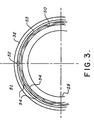
- FIG. 3 shows the preferred embodiment for transferring heat by conduction from the outer ring 18 to the outer housing 32.
- a similar arrangement conducts heat from the inner ring 25 to the inner housing 31.
- a wavy (sinusoidal) spring 50 is inserted in a circumferential slot between the outer ring 19 and an insulator 51, the latter being provided with a gap 52 which allows the walls of the insulator 51 to be forced into intimate contact with the wall of the housing 32 by the action of the wavy spring 50.
- Various thickness optimising shims 53 may be inserted between the spring 50 and the housing 32 until maximum heat conduction through contact points 54 is achieved.
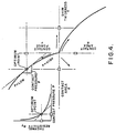
- a shim 53 thickness which results in minimum temperature differential between the ring 19 and the housing 32 for a given heat source at the ring 19 is that thickness which provides optimum heat transfer efficiency.
- contact area A of the wavy spring 50 at the outer ring 32 and at the insulator 51 is also affected by the various shim 53 thicknesses. Since both the normal force F and the area A are being influenced but not equally, the ratio of the two, normal pressure P, is also changing with shim 53 thickness. The heat transfer is effected by the thermal resistivity R T and the area of contact A. Starting at the optimum point shown in Figure 4, as shim 53 thickness T increases, contact force F and contact area A increase, contact pressure P decreases and resistivity R T increases. Since the resistivity R T is increasing faster than is the area A, the heat transfer Q decreases.
- Figure 1 shows the spiral configuration of the terminals on the outer housing 32 to which the cables 23 are attached.
- Figure 1 also shows the advantage provided by the axial reversibility of the terminals. These terminals may be reversed, even in the field, by removing and reassembling the stiffening bolt 20, backing ring 22 and terminal cone 14 on any selected circuit connection.
- the thimble lock 16 provides a positive cone interface 15 clamping action of the thimbles 11.
- the short preload loops 21 a assure a positive and low interface resistivity even under the bending moment influence from external cable deflections and movements.
Landscapes
- Engineering & Computer Science (AREA)
- Remote Sensing (AREA)
- Aviation & Aerospace Engineering (AREA)
- Power Engineering (AREA)
- Connector Housings Or Holding Contact Members (AREA)
- Ultra Sonic Daignosis Equipment (AREA)
Claims (2)
Applications Claiming Priority (2)
| Application Number | Priority Date | Filing Date | Title |
|---|---|---|---|
| US751757 | 1985-07-03 | ||
| US06/751,757 US4650266A (en) | 1985-07-03 | 1985-07-03 | Rotary high power transfer apparatus |
Publications (2)
| Publication Number | Publication Date |
|---|---|
| EP0211501A1 EP0211501A1 (fr) | 1987-02-25 |
| EP0211501B1 true EP0211501B1 (fr) | 1990-04-11 |
Family
ID=25023361
Family Applications (1)
| Application Number | Title | Priority Date | Filing Date |
|---|---|---|---|
| EP86304843A Expired EP0211501B1 (fr) | 1985-07-03 | 1986-06-24 | Dispositif tournant pour transmission d'énergie |
Country Status (4)
| Country | Link |
|---|---|
| US (1) | US4650266A (fr) |
| EP (1) | EP0211501B1 (fr) |
| JP (1) | JPH073798B2 (fr) |
| DE (1) | DE3670405D1 (fr) |
Families Citing this family (5)
| Publication number | Priority date | Publication date | Assignee | Title |
|---|---|---|---|---|
| JPS6165812A (ja) * | 1984-09-07 | 1986-04-04 | Lion Corp | 歯磨組成物 |
| US5429508A (en) * | 1994-01-26 | 1995-07-04 | Methode Electronics, Inc. | Automobile steering column interconnector |
| US5775920A (en) * | 1995-09-01 | 1998-07-07 | Methode Electronics, Inc. | Rolling elastomer contact clockspring |
| CN106895051B (zh) * | 2017-03-21 | 2019-02-19 | 哈尔滨工业大学 | 一种重复对接锁定与分离装置 |
| CN116552822A (zh) * | 2023-05-29 | 2023-08-08 | 上海宇航系统工程研究所 | 一种空间大型驱动机构 |
Family Cites Families (9)
| Publication number | Priority date | Publication date | Assignee | Title |
|---|---|---|---|---|
| FR752770A (fr) * | 1933-03-20 | 1933-09-30 | Le Massif Central Electr | Dispositif de connexion électrique |
| FR875583A (fr) * | 1941-05-28 | 1942-09-28 | Comp Generale Electricite | Raccord de branchement démontable pour rcâbles |
| FR989777A (fr) * | 1949-04-28 | 1951-09-13 | Entpr S Soc Gen | Dispositif perfectionné pour le déroulement de câbles |
| CH335537A (fr) * | 1956-03-10 | 1959-01-15 | Comp Generale Electricite | Dispositif à contacts glissants électriques |
| FR1511618A (fr) * | 1966-12-19 | 1968-02-02 | Chausson Usines Sa | Procédé pour la fabrication de dissipateurs de chaleur du type à fils et dissipateur en résultant |
| GB1453994A (en) * | 1973-04-06 | 1976-10-27 | Siemens Ag | Electrical connectors |
| US4068909A (en) * | 1977-01-14 | 1978-01-17 | Sperry Rand Corporation | Electrical contact assembly and method and apparatus for assembling the same |
| US4098546A (en) * | 1977-01-14 | 1978-07-04 | Sperry Rand Corporation | Electrical conductor assembly |
| US4372633A (en) * | 1981-04-17 | 1983-02-08 | Sperry Corporation | High current transfer roll ring assembly |
-
1985
- 1985-07-03 US US06/751,757 patent/US4650266A/en not_active Expired - Lifetime
-
1986
- 1986-06-24 DE DE8686304843T patent/DE3670405D1/de not_active Expired - Fee Related
- 1986-06-24 EP EP86304843A patent/EP0211501B1/fr not_active Expired
- 1986-07-01 JP JP61154964A patent/JPH073798B2/ja not_active Expired - Lifetime
Also Published As
| Publication number | Publication date |
|---|---|
| US4650266A (en) | 1987-03-17 |
| JPS6217969A (ja) | 1987-01-26 |
| EP0211501A1 (fr) | 1987-02-25 |
| DE3670405D1 (de) | 1990-05-17 |
| JPH073798B2 (ja) | 1995-01-18 |
Similar Documents
| Publication | Publication Date | Title |
|---|---|---|
| US5358432A (en) | Resilient connectors for a generator/motor rotor | |
| EP0112618B1 (fr) | Dispositif de connexion à élément d'entraînement métallique thermorétractable | |
| US4006288A (en) | High voltage shielded cable termination, splice connection, and method of making a splice connection | |
| CN101919126B (zh) | 用于波纹电缆的同轴电缆连接器 | |
| US4925403A (en) | Coaxial transmission medium connector | |
| US4372633A (en) | High current transfer roll ring assembly | |
| US4335927A (en) | Multi-circuit rotary electrical conductor assembly | |
| US5851120A (en) | Rotary conduit/ball connector | |
| EP0711003B1 (fr) | Connecteur rotatif sans balais | |
| GB2193853A (en) | Floating coaxial connector | |
| JP2020177914A (ja) | 導電スリップリング | |
| JPS62501048A (ja) | 整流器組立体 | |
| JP2828892B2 (ja) | 光ファイバ相互接続装置 | |
| GB2040114A (en) | High voltage electrical connector shield | |
| EP0211501A1 (fr) | Dispositif tournant pour transmission d'énergie | |
| US5205749A (en) | Electric plug-and-socket connection | |
| US4173384A (en) | Flexible co-axial connector for cable in-line electronics | |
| GB1579734A (en) | Methods of making electrical connections and connectors for use therein | |
| US5065059A (en) | Field coil pole to pole connector with high cyclic duty capability | |
| US4091299A (en) | Device to electrically connect rotor winding of synchronous electrical machine to exciter | |
| EP0968561A1 (fr) | Traversee isolee de sortie electrique destinee a etre utilisee sur un turbogenerateur | |
| Jacobson et al. | Rotary high power transfer apparatus | |
| US4014599A (en) | Device for electrical coupling of generator and exciter rotor current leads | |
| EP0991138A2 (fr) | Connecteur électrique avec un élément de mise à la terre | |
| US20230178919A1 (en) | Contact Assembly |
Legal Events
| Date | Code | Title | Description |
|---|---|---|---|
| PUAI | Public reference made under article 153(3) epc to a published international application that has entered the european phase |
Free format text: ORIGINAL CODE: 0009012 |
|
| AK | Designated contracting states |
Kind code of ref document: A1 Designated state(s): DE FR GB |
|
| 17P | Request for examination filed |
Effective date: 19870327 |
|
| RAP1 | Party data changed (applicant data changed or rights of an application transferred) |
Owner name: HONEYWELL INC. |
|
| 17Q | First examination report despatched |
Effective date: 19880628 |
|
| GRAA | (expected) grant |
Free format text: ORIGINAL CODE: 0009210 |
|
| AK | Designated contracting states |
Kind code of ref document: B1 Designated state(s): DE FR GB |
|
| ET | Fr: translation filed | ||
| REF | Corresponds to: |
Ref document number: 3670405 Country of ref document: DE Date of ref document: 19900517 |
|
| PLBE | No opposition filed within time limit |
Free format text: ORIGINAL CODE: 0009261 |
|
| STAA | Information on the status of an ep patent application or granted ep patent |
Free format text: STATUS: NO OPPOSITION FILED WITHIN TIME LIMIT |
|
| 26N | No opposition filed | ||
| ITF | It: translation for a ep patent filed | ||
| REG | Reference to a national code |
Ref country code: GB Ref legal event code: IF02 |
|
| PGFP | Annual fee paid to national office [announced via postgrant information from national office to epo] |
Ref country code: DE Payment date: 20040630 Year of fee payment: 19 |
|
| PGFP | Annual fee paid to national office [announced via postgrant information from national office to epo] |
Ref country code: GB Payment date: 20050506 Year of fee payment: 20 |
|
| PGFP | Annual fee paid to national office [announced via postgrant information from national office to epo] |
Ref country code: FR Payment date: 20050602 Year of fee payment: 20 |
|
| REG | Reference to a national code |
Ref country code: GB Ref legal event code: PE20 |
|
| PG25 | Lapsed in a contracting state [announced via postgrant information from national office to epo] |
Ref country code: DE Free format text: LAPSE BECAUSE OF NON-PAYMENT OF DUE FEES Effective date: 20060103 |
|
| PG25 | Lapsed in a contracting state [announced via postgrant information from national office to epo] |
Ref country code: GB Free format text: LAPSE BECAUSE OF EXPIRATION OF PROTECTION Effective date: 20060623 |
|
| P01 | Opt-out of the competence of the unified patent court (upc) registered |
Effective date: 20230525 |