EP0211685A2 - Ejektor, insbesondere für die Neutralisation von wässrigen alkalischen Lösungen mit Kohlendioxid - Google Patents
Ejektor, insbesondere für die Neutralisation von wässrigen alkalischen Lösungen mit Kohlendioxid Download PDFInfo
- Publication number
- EP0211685A2 EP0211685A2 EP86306334A EP86306334A EP0211685A2 EP 0211685 A2 EP0211685 A2 EP 0211685A2 EP 86306334 A EP86306334 A EP 86306334A EP 86306334 A EP86306334 A EP 86306334A EP 0211685 A2 EP0211685 A2 EP 0211685A2
- Authority
- EP
- European Patent Office
- Prior art keywords
- ejector
- section
- gas
- intermediate section
- aqueous alkaline
- Prior art date
- Legal status (The legal status is an assumption and is not a legal conclusion. Google has not performed a legal analysis and makes no representation as to the accuracy of the status listed.)
- Granted
Links
Images


Classifications
-
- C—CHEMISTRY; METALLURGY
- C02—TREATMENT OF WATER, WASTE WATER, SEWAGE, OR SLUDGE
- C02F—TREATMENT OF WATER, WASTE WATER, SEWAGE, OR SLUDGE
- C02F3/00—Biological treatment of water, waste water, or sewage
- C02F3/02—Aerobic processes
- C02F3/12—Activated sludge processes
- C02F3/1278—Provisions for mixing or aeration of the mixed liquor
- C02F3/1294—"Venturi" aeration means
-
- B—PERFORMING OPERATIONS; TRANSPORTING
- B01—PHYSICAL OR CHEMICAL PROCESSES OR APPARATUS IN GENERAL
- B01F—MIXING, e.g. DISSOLVING, EMULSIFYING OR DISPERSING
- B01F25/00—Flow mixers; Mixers for falling materials, e.g. solid particles
- B01F25/30—Injector mixers
- B01F25/31—Injector mixers in conduits or tubes through which the main component flows
- B01F25/314—Injector mixers in conduits or tubes through which the main component flows wherein additional components are introduced at the circumference of the conduit
- B01F25/3142—Injector mixers in conduits or tubes through which the main component flows wherein additional components are introduced at the circumference of the conduit the conduit having a plurality of openings in the axial direction or in the circumferential direction
-
- B—PERFORMING OPERATIONS; TRANSPORTING
- B01—PHYSICAL OR CHEMICAL PROCESSES OR APPARATUS IN GENERAL
- B01F—MIXING, e.g. DISSOLVING, EMULSIFYING OR DISPERSING
- B01F25/00—Flow mixers; Mixers for falling materials, e.g. solid particles
- B01F25/30—Injector mixers
- B01F25/31—Injector mixers in conduits or tubes through which the main component flows
- B01F25/314—Injector mixers in conduits or tubes through which the main component flows wherein additional components are introduced at the circumference of the conduit
- B01F25/3142—Injector mixers in conduits or tubes through which the main component flows wherein additional components are introduced at the circumference of the conduit the conduit having a plurality of openings in the axial direction or in the circumferential direction
- B01F25/31425—Injector mixers in conduits or tubes through which the main component flows wherein additional components are introduced at the circumference of the conduit the conduit having a plurality of openings in the axial direction or in the circumferential direction with a plurality of perforations in the axial and circumferential direction covering the whole surface
-
- C—CHEMISTRY; METALLURGY
- C02—TREATMENT OF WATER, WASTE WATER, SEWAGE, OR SLUDGE
- C02F—TREATMENT OF WATER, WASTE WATER, SEWAGE, OR SLUDGE
- C02F1/00—Treatment of water, waste water, or sewage
- C02F1/66—Treatment of water, waste water, or sewage by neutralisation; pH adjustment
-
- B—PERFORMING OPERATIONS; TRANSPORTING
- B01—PHYSICAL OR CHEMICAL PROCESSES OR APPARATUS IN GENERAL
- B01F—MIXING, e.g. DISSOLVING, EMULSIFYING OR DISPERSING
- B01F2215/00—Auxiliary or complementary information in relation with mixing
- B01F2215/04—Technical information in relation with mixing
- B01F2215/0413—Numerical information
- B01F2215/0418—Geometrical information
- B01F2215/0431—Numerical size values, e.g. diameter of a hole or conduit, area, volume, length, width, or ratios thereof
-
- B—PERFORMING OPERATIONS; TRANSPORTING
- B01—PHYSICAL OR CHEMICAL PROCESSES OR APPARATUS IN GENERAL
- B01F—MIXING, e.g. DISSOLVING, EMULSIFYING OR DISPERSING
- B01F23/00—Mixing according to the phases to be mixed, e.g. dispersing or emulsifying
- B01F23/20—Mixing gases with liquids
- B01F23/23—Mixing gases with liquids by introducing gases into liquid media, e.g. for producing aerated liquids
-
- B—PERFORMING OPERATIONS; TRANSPORTING
- B01—PHYSICAL OR CHEMICAL PROCESSES OR APPARATUS IN GENERAL
- B01F—MIXING, e.g. DISSOLVING, EMULSIFYING OR DISPERSING
- B01F23/00—Mixing according to the phases to be mixed, e.g. dispersing or emulsifying
- B01F23/20—Mixing gases with liquids
- B01F23/23—Mixing gases with liquids by introducing gases into liquid media, e.g. for producing aerated liquids
- B01F23/237—Mixing gases with liquids by introducing gases into liquid media, e.g. for producing aerated liquids characterised by the physical or chemical properties of gases or vapours introduced in the liquid media
- B01F23/2373—Mixing gases with liquids by introducing gases into liquid media, e.g. for producing aerated liquids characterised by the physical or chemical properties of gases or vapours introduced in the liquid media for obtaining fine bubbles, i.e. bubbles with a size below 100 µm
-
- Y—GENERAL TAGGING OF NEW TECHNOLOGICAL DEVELOPMENTS; GENERAL TAGGING OF CROSS-SECTIONAL TECHNOLOGIES SPANNING OVER SEVERAL SECTIONS OF THE IPC; TECHNICAL SUBJECTS COVERED BY FORMER USPC CROSS-REFERENCE ART COLLECTIONS [XRACs] AND DIGESTS
- Y02—TECHNOLOGIES OR APPLICATIONS FOR MITIGATION OR ADAPTATION AGAINST CLIMATE CHANGE
- Y02W—CLIMATE CHANGE MITIGATION TECHNOLOGIES RELATED TO WASTEWATER TREATMENT OR WASTE MANAGEMENT
- Y02W10/00—Technologies for wastewater treatment
- Y02W10/10—Biological treatment of water, waste water, or sewage
-
- Y—GENERAL TAGGING OF NEW TECHNOLOGICAL DEVELOPMENTS; GENERAL TAGGING OF CROSS-SECTIONAL TECHNOLOGIES SPANNING OVER SEVERAL SECTIONS OF THE IPC; TECHNICAL SUBJECTS COVERED BY FORMER USPC CROSS-REFERENCE ART COLLECTIONS [XRACs] AND DIGESTS
- Y10—TECHNICAL SUBJECTS COVERED BY FORMER USPC
- Y10S—TECHNICAL SUBJECTS COVERED BY FORMER USPC CROSS-REFERENCE ART COLLECTIONS [XRACs] AND DIGESTS
- Y10S261/00—Gas and liquid contact apparatus
- Y10S261/75—Flowing liquid aspirates gas
Definitions
- This invention relates to an ejector, and in particular to an ejector to be used for injecting C0 2 into alkaline solutions for neutralizing those alkaline solutions.
- Carbon dioxide is being used as a neutralizer of aqueous alkaline solutions in lieu of strong acids.
- Venturi tubes consist basically of four main sections, namely: a cylindical entrance section, a converging section, a reduced diameter (bottleneck) cylindrical section and an exit diverging section.
- the present invention aims to achieve efficiency levels of about 90% through a perfect mixture of the two fluids, one in the liquid phase (water) and the other in the gas phase (C0 2 ), by incorporating changes into the conventional Venturi tube.
- the present invention accordingly provides an ejector for use in a process for the neutralization of an aqueous alkaline solution with C0 2 gas comprising a converging section which promotes an increase of speed of the aqueous alkaline solution by transfer thereof from one section of larger diameter to one of smaller diameter; an intermediate section in which the liquid-C0 2 reaction takes place; and a diverging section in which the turbulent mixture regime between the liquid phase and the C0 2 in gas form occurs, the neutralization reaction being complemented by the mixture.
- the present invention further provides a method of neutralizing aqueous alkaline solutions with C0 2 gas, the method comprising the steps of:-
- an ejector 10 comprises, in turn, a cylindrical entrance section 12, a converging section 14, a reduced diameter (bottleneck) section 16 and a diverging exit section 18.
- the cylindrical entrance section 12 comprises an annular wall 20 which is integral with the converging section 14 which comprises an inwardly converging circumferential wall 22.
- the bottleneck section 16 comprises an inner tubular member 24 and an outer tubular member 26 which are coaxial.
- the outer tubular member 26 surrounds the inner tubular member 24 thereby to define an annular chamber therebetween.
- the outer tubular member 26 is provided with a threaded coupling 28 for connection to a source of carbon dioxide.
- the inner tubular member 24 has a number of holes 30 drilled therethrough distributed over the area of the inner tubular member 24.
- Each hole 30 has a diameter of from 0.5 to 0.6 mm and is inclined at an angle of 60° to the longitudinal axis of the ejector 10.
- a plurality of hollow needles 32 extend from the chamber 28 through the inner tubular member 24 and into the central cavity of the ejector 10.
- the hollow needles 32 are also inclined to the longitudinal axis of the ejector and at the same angle thereto as the holes 30. As is shown in Figure 3, each hollow needle 32 is inclined at an angle of 30° to the direction of the flow of water through the ejector.
- the hollow needles have an internal diameter of 0.3 mm and alternate lengths ranging from 25 to 30 mm.
- the entrance end of the bottleneck section 16 is connected to the converging section 14.
- the exit end of the bottleneck section 16 is connected to the diverging exit section 18 which comprises an outwardly diverging annular wall 34.
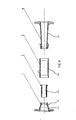
- the ejector 10 is constructed in four separable parts for ease of maintenance and cleaning due to the severe operating conditions to which the ejector is in use subjected.
- the four separable parts are shown in Figure 4 which shows a first part 1 comprising the cylindrical entrance section 12 and the converging section 14, a second part 2 comprising the inner tubular member 24 of the bottleneck section 16, a third part 3 comprising the outer tubular member 26 of the bottleneck section 16, and a fourth part 4 comprising the diverging exit section 18.
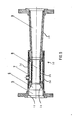
- Figure 5 shows the cavities present in the ejector 10 of the present invention.
- a cylindrical cavity 5 defined by the cylindrical entrance section 12.
- Adjacent to the cylindrical cavity 5 is a converging frustoconical cavity 6 defined by the converging section 14.
- An annular cavity 7 is defined between the inner and outer tubular members, 24, 26.
- the bottleneck section 16 defines a reduced diameter cylindrical cavity 8 and the diverging section defines a diverging frustoconical cavity 9.
- These needles are also inclined at an angle of 30° in the direction of the flow of water.
- the main purpose of the presence of these needles 32 and of the micro-holes 30 is to promote the injection of C0 2 at different points of the cross-section of the water flow through the bottleneck section 16.
- the ejector developed is composed basically of three sections:
- the C0 2 injection takes place through micro-holes 30 located on the surface of the inner tubular member 24, preferentially one of teflon, and also through needles 32 located at an angle of 30° to the surface of the inner tubular member 24 promoting and materially increasing the gas-liquid mixture and consequently the neutralizing reaction.
- micro-holes 30 located on the surface inject gas towards the larger diameter area of the water flow passing through the ejector 16, while the needles 32 inject the gas radially from the center of flow.
- - diverging section 18 it is in this area that the turbulent mixture of the liquid and gas phase occurs, the neutralizing reaction being completed by the mixture.
- the ejector is sized in accordance with the water flow of the system.
- the ejector which is the subject of this invention is a static item, that is, it has no moving parts, but it uses kinetic energy from the water flow provided by a centrifugal pump to effect the gas-liquid mixture.
- the effluent enters the cylindrical entrance section, following this the flow is bottlenecked in the converging section of the ejector. This allows a reduction in static pressure and an increase in speed of flow of the effluent.
- the gas bubbles Due to the high speed of the effluent the gas bubbles are reduced to diameters measurable in microns and from this point on are distributed along the cross-section of the flow through the micro-holes and the radially positioned needles.
- the speed of the water, the even distribution of the gas, the diameters and location of the holes, and the use of needles to inject the gas all combined, allow a perfect homogenization of gas/liquid with gas in the form of thousands of micro-bubbles.
- the efficiency of the chemical reaction to neutralize alkaline effluents with C0 2 depends closely on the perfect interaction of the mixture of the liquid and gas phases. This is particularly important when the concentration of the alkaline substance is at very low levels, consequently requiring smaller quantities of CO 2 .
- the gas be dispersed in the form of micro-bubbles throughout the entire volume taken by the flow of the water.
Landscapes
- Chemical & Material Sciences (AREA)
- Life Sciences & Earth Sciences (AREA)
- Organic Chemistry (AREA)
- Hydrology & Water Resources (AREA)
- Engineering & Computer Science (AREA)
- Environmental & Geological Engineering (AREA)
- Water Supply & Treatment (AREA)
- Chemical Kinetics & Catalysis (AREA)
- Biodiversity & Conservation Biology (AREA)
- Microbiology (AREA)
- Physical Or Chemical Processes And Apparatus (AREA)
- Organic Low-Molecular-Weight Compounds And Preparation Thereof (AREA)
- Gas Separation By Absorption (AREA)
Applications Claiming Priority (2)
| Application Number | Priority Date | Filing Date | Title |
|---|---|---|---|
| BR8503919A BR8503919A (pt) | 1985-08-16 | 1985-08-16 | Ejetor para o processo co2 na neutralizacao de aguas alcalinas |
| BR8503919 | 1985-08-16 |
Publications (3)
| Publication Number | Publication Date |
|---|---|
| EP0211685A2 true EP0211685A2 (de) | 1987-02-25 |
| EP0211685A3 EP0211685A3 (en) | 1987-10-07 |
| EP0211685B1 EP0211685B1 (de) | 1991-03-06 |
Family
ID=4038395
Family Applications (1)
| Application Number | Title | Priority Date | Filing Date |
|---|---|---|---|
| EP86306334A Expired - Lifetime EP0211685B1 (de) | 1985-08-16 | 1986-08-15 | Ejektor, insbesondere für die Neutralisation von wässrigen alkalischen Lösungen mit Kohlendioxid |
Country Status (9)
| Country | Link |
|---|---|
| US (1) | US4743405A (de) |
| EP (1) | EP0211685B1 (de) |
| JP (1) | JPH0824832B2 (de) |
| BR (1) | BR8503919A (de) |
| CA (1) | CA1291583C (de) |
| DE (1) | DE3677850D1 (de) |
| ES (1) | ES2001234A6 (de) |
| MX (1) | MX170387B (de) |
| TR (1) | TR23302A (de) |
Cited By (11)
| Publication number | Priority date | Publication date | Assignee | Title |
|---|---|---|---|---|
| DE3810950A1 (de) * | 1988-03-31 | 1989-10-12 | Klein Schanzlin & Becker Ag | Entgasungseinrichtung |
| DE9201154U1 (de) * | 1992-01-31 | 1993-06-03 | Oematech oekologische Maschinenbautechnik GmbH, O-4500 Dessau | Vorrichtung zum kontinuierlichen Einbringen von Gas in eine Flüssigkeit |
| FR2756871A1 (fr) * | 1996-12-05 | 1998-06-12 | Mtu Friedrichshafen Gmbh | Element de raccordement pour l'introduction de carburant et d'un second fluide dans un injecteur |
| US6074085A (en) * | 1997-12-20 | 2000-06-13 | Usbi Co. | Cyclonic mixer |
| FR2969997A1 (fr) * | 2010-12-30 | 2012-07-06 | Equip Chantiers Et Locations | Dispositif de recylcage et de traitement d'une eau de lavage chargee en particules, notamment cimentaires |
| WO2014163685A1 (en) * | 2013-03-12 | 2014-10-09 | Rolls-Royce North American Technologies, Inc. | Deoxygenation of liquid with gas |
| EP2552574A4 (de) * | 2010-04-02 | 2016-02-17 | William B Kerfoot | Nanobläschengenerator und bearbeitungsverfahren damit |
| EP3268306A4 (de) * | 2015-04-16 | 2018-09-19 | Nanovapor Inc. | Vorrichtung zur nanopartikelerzeugung |
| IT201900022155A1 (it) * | 2019-11-26 | 2021-05-26 | Elettra Srl | Apparecchiatura per l'applicazione di emulsione siliconica su carta stampata |
| KR20220012642A (ko) | 2020-07-23 | 2022-02-04 | 주식회사 엘지화학 | 이젝터 |
| US12515179B2 (en) | 2015-02-11 | 2026-01-06 | Eco2Mix Inc. | Equipment and process for liquid/gas reaction or mix |
Families Citing this family (57)
| Publication number | Priority date | Publication date | Assignee | Title |
|---|---|---|---|---|
| US4861352A (en) * | 1987-12-30 | 1989-08-29 | Union Carbide Corporation | Method of separating a gas and/or particulate matter from a liquid |
| US4931225A (en) * | 1987-12-30 | 1990-06-05 | Union Carbide Industrial Gases Technology Corporation | Method and apparatus for dispersing a gas into a liquid |
| US5814210A (en) * | 1988-01-27 | 1998-09-29 | Virginia Tech Intellectual Properties, Inc. | Apparatus and process for the separation of hydrophobic and hydrophilic particles using microbubble column flotation together with a process and apparatus for generation of microbubbles |
| US4981582A (en) * | 1988-01-27 | 1991-01-01 | Virginia Tech Intellectual Properties, Inc. | Process and apparatus for separating fine particles by microbubble flotation together with a process and apparatus for generation of microbubbles |
| US5167798A (en) * | 1988-01-27 | 1992-12-01 | Virginia Tech Intellectual Properties, Inc. | Apparatus and process for the separation of hydrophobic and hydrophilic particles using microbubble column flotation together with a process and apparatus for generation of microbubbles |
| US4911836A (en) * | 1988-08-08 | 1990-03-27 | Haggerty T G | Submerged aeration system |
| US4971731A (en) * | 1988-10-21 | 1990-11-20 | Deister Concentrator Company, Inc. | Method and apparatus for generating microbubbles in froth flotation mineral concentration systems |
| US5102104A (en) * | 1990-03-05 | 1992-04-07 | U.S. Gold Corporation | Biological conversion apparatus |
| DE4029982C2 (de) * | 1990-09-21 | 2000-08-10 | Steinecker Anton Entwicklung | Vorrichtung zum Begasen einer Flüssigkeit |
| AU652420B2 (en) * | 1991-02-01 | 1994-08-25 | Roussel-Uclaf | Dispensing method and apparatus |
| US5143543A (en) * | 1991-08-23 | 1992-09-01 | U.S. Gold Corporation | Biological conversion method |
| DE9111657U1 (de) * | 1991-09-18 | 1991-11-14 | Anton Steinecker Entwicklungs-GmbH & Co., 8050 Freising | Belüftungsdüse für Flüssigkeiten |
| JP3161734B2 (ja) | 1991-12-02 | 2001-04-25 | テクノロジカル リソーシィズ プロプライエタリー リミテッド | 反応装置 |
| WO1994001210A1 (en) * | 1992-07-09 | 1994-01-20 | Technological Resources Pty. Limited | A reactor |
| DE9302862U1 (de) * | 1993-02-26 | 1993-05-27 | Anton Steinecker Entwicklungs GmbH & Co, 8050 Freising | Belüftungsdüse zum Belüften von organische Substanzen enthaltenden Flüssigkeiten |
| JP3443728B2 (ja) * | 1998-02-09 | 2003-09-08 | 孝 山本 | 汚水の浄化処理装置 |
| DE19905572A1 (de) * | 1999-02-11 | 2000-08-31 | Bayer Ag | Vorrichtung zum Mischen und Reagieren mehrphasiger gasförmiger und flüssiger Gemische und Verwendung dieser Vorrichtung |
| US6237897B1 (en) * | 1999-04-29 | 2001-05-29 | Antonio Marina | Oxygenator |
| IT1306856B1 (it) * | 1999-06-07 | 2001-10-11 | Ct Sviluppo Materiali Spa | Dispositivo per solubilizzare un aeriforme in fluido, ed uso di dettodispositivo. |
| FI107829B (fi) * | 1999-06-15 | 2001-10-15 | Markku Juhani Palmu | Laite kaasun imemiseksi ja sekoittamiseksi polttonesteen virtaukseen |
| RU2201902C2 (ru) * | 2001-02-19 | 2003-04-10 | Открытое акционерное общество "Сибирский научно-исследовательский институт лесной и целлюлозно-бумажной промышленности" | Система аэрации сточных вод |
| US6682057B2 (en) | 2001-05-01 | 2004-01-27 | Estr, Inc. | Aerator and wastewater treatment system |
| US6767007B2 (en) | 2002-03-25 | 2004-07-27 | Homer C. Luman | Direct injection contact apparatus for severe services |
| US20060087910A1 (en) * | 2003-02-15 | 2006-04-27 | Darrell Knepp | Water injection method and apparatus for concrete mixer |
| US20040251566A1 (en) * | 2003-06-13 | 2004-12-16 | Kozyuk Oleg V. | Device and method for generating microbubbles in a liquid using hydrodynamic cavitation |
| US6981997B2 (en) * | 2003-07-18 | 2006-01-03 | Praxair Technology, Inc. | Deaeration of water and other liquids |
| NO20042102A (no) * | 2004-05-21 | 2005-05-30 | Aga As | Dyse ved oksygenering |
| DE602005016960D1 (de) * | 2004-12-17 | 2009-11-12 | Shell Int Research | Rohrteil zum befördern eines festen partikelmaterials |
| NO325976B1 (no) * | 2006-01-26 | 2008-08-25 | Gba Marine As | Anordning for absorpsjon av gass eller damp i vaeske og fremgangsmate ved reintrodusering av damp eller gass i vaeske som gassen eller dampen stammer fra |
| JP4942434B2 (ja) * | 2006-06-20 | 2012-05-30 | シャープ株式会社 | 微細気泡発生器 |
| WO2008127533A1 (en) * | 2007-04-13 | 2008-10-23 | Freeman Energy Corporation | Biomass cultivation system and corresponding method of operation |
| US8066027B2 (en) * | 2008-07-30 | 2011-11-29 | Sprague Alden C | Vacuum activated closed loop system |
| JP4871927B2 (ja) * | 2008-08-19 | 2012-02-08 | 株式会社ティーエヌケー | 色識別ステッキ |
| US8544492B2 (en) * | 2009-07-25 | 2013-10-01 | Alden C. Sprague | Vacuum activated power tower |
| CA2834219A1 (en) * | 2011-04-26 | 2012-11-01 | G Tech Licensing, Llc | Gas dissolving apparatus |
| JP5884995B2 (ja) * | 2013-12-02 | 2016-03-15 | Jfeエンジニアリング株式会社 | 凝縮混合装置及びこれを有する蒸発ガス再液化装置 |
| JP5945974B2 (ja) * | 2013-12-02 | 2016-07-05 | Jfeエンジニアリング株式会社 | 凝縮混合装置及びこれを有する蒸発ガス再液化装置 |
| KR101673139B1 (ko) * | 2014-04-15 | 2016-11-22 | 이여형 | 벤츄리 구조의 단면을 가지는 메쉬 타공망을 이용한 용존관 |
| CN104533846A (zh) * | 2014-12-16 | 2015-04-22 | 中国航天科技集团公司第六研究院第十一研究所 | 一种适用于泵压式供应系统的高压环形射流泵 |
| US10512278B2 (en) * | 2015-04-24 | 2019-12-24 | Messer Industries Usa, Inc. | Inline mixing injector for liquid products |
| CN104815606B (zh) * | 2015-05-14 | 2016-08-24 | 神华集团有限责任公司 | 气相聚合系统及其喷嘴装置 |
| WO2016194056A1 (ja) * | 2015-05-29 | 2016-12-08 | Jfeエンジニアリング株式会社 | 凝縮混合装置及びこれを有する蒸発ガス再液化装置 |
| US10058828B2 (en) * | 2015-06-01 | 2018-08-28 | Cameron International Corporation | Apparatus for mixing of fluids flowing through a conduit |
| JP6090616B2 (ja) * | 2016-05-30 | 2017-03-08 | Jfeエンジニアリング株式会社 | 凝縮混合装置及びこれを有する蒸発ガス再液化装置 |
| JP6673749B2 (ja) * | 2016-05-31 | 2020-03-25 | Jfeエンジニアリング株式会社 | 気液混合器 |
| US11168951B2 (en) * | 2016-07-14 | 2021-11-09 | General Electric Company | Entrainment heat exchanger |
| US10744468B2 (en) * | 2016-08-18 | 2020-08-18 | Praxair Technology, Inc. | System and method for feeding gas into liquid |
| KR102130794B1 (ko) * | 2018-04-17 | 2020-08-05 | 주식회사 에코스코리아 | 급속 혼합기 및 그를 포함하는 중화장치 |
| KR102658128B1 (ko) * | 2019-11-07 | 2024-04-16 | 엘지전자 주식회사 | 가스 퍼니스 |
| AU2021244299A1 (en) * | 2020-03-24 | 2022-10-27 | Moleaer, Inc | Nano-bubble generating apparatus and method |
| US11492274B2 (en) * | 2020-05-28 | 2022-11-08 | National Chiao Tung University | Liquid treatment apparatus |
| IT202000016327A1 (it) * | 2020-07-06 | 2022-01-06 | Omitaly Srl | Dispositivo generatore di micro e nano bolle |
| JP2023540815A (ja) * | 2021-01-25 | 2023-09-26 | 筆 鐘 | 超微粉末を調製するための分散型気体噴出構造 |
| CN112774543A (zh) * | 2021-01-25 | 2021-05-11 | 钟笔 | 一种用于超微粉制备的分布式气体喷出结构 |
| CA3206365A1 (en) * | 2021-01-26 | 2022-08-04 | Benjamin Arcand | Syringe-based microbubble generator with an aerator |
| EP4433014B1 (de) | 2021-11-19 | 2025-09-03 | Sundance Spas, Inc. | Selbsthaltende heisswanne oder bad |
| US20240390849A1 (en) * | 2023-05-25 | 2024-11-28 | Knuco 1, Llc | System and method for gas mitigation |
Family Cites Families (21)
| Publication number | Priority date | Publication date | Assignee | Title |
|---|---|---|---|---|
| US1747687A (en) * | 1925-12-05 | 1930-02-18 | Bleach Process Company | Absorption method and apparatus |
| DE1459453B2 (de) * | 1963-11-20 | 1972-04-20 | Asendorf, Knut Erich, 6380 Bad Horn bürg | Abwasserklaeranlage |
| US3371618A (en) * | 1966-02-18 | 1968-03-05 | Chambers John | Pump |
| US3409274A (en) * | 1967-11-22 | 1968-11-05 | Combustion Eng | Mixing apparatus for high pressure fluids at different temperatures |
| US3927152A (en) * | 1971-03-12 | 1975-12-16 | Fmc Corp | Method and apparatus for bubble shearing |
| DE2361298C2 (de) * | 1972-12-28 | 1983-03-10 | VEB Chemieanlagenbaukombinat Leipzig-Grimma, DDR 7240 Grimma | Anlage zur Begasung von Flüssigkeiten, insbesondere von Fermentationsflüssigkeiten |
| JPS49130564A (de) * | 1973-04-23 | 1974-12-13 | ||
| DE2454526A1 (de) * | 1974-11-16 | 1976-05-20 | Fuellpack Dipl Brauerei Ing Di | Einrichtung zur neutralisation von abwaessern |
| US4215082A (en) * | 1975-02-25 | 1980-07-29 | Societe Anonyme dete: Alsthom-Atlantique | Device for injecting a gas into a liquid |
| US4166790A (en) * | 1975-04-17 | 1979-09-04 | Bayer Aktiengesellschaft | Single stage process for continuous introduction of oxygen-containing gases into effluent containing activated sludge |
| FR2315983A1 (fr) * | 1975-07-04 | 1977-01-28 | Tepral | Injecteur-melangeur a effet venturi et a haut rendement |
| JPS5234841U (de) * | 1975-09-03 | 1977-03-11 | ||
| US4198359A (en) * | 1976-07-26 | 1980-04-15 | Todd John J | Apparatus for gasification of liquids |
| US4333833A (en) * | 1978-05-08 | 1982-06-08 | Fischer & Porter Co. | In-line disinfectant contactor |
| EP0037513B1 (de) * | 1980-04-09 | 1984-08-08 | Feldmühle Aktiengesellschaft | Flotationsvorrichtung zum Deinken von Faserstoffsuspensionen |
| US4474477A (en) * | 1983-06-24 | 1984-10-02 | Barrett, Haentjens & Co. | Mixing apparatus |
| DE3325969A1 (de) * | 1983-07-19 | 1985-01-31 | Klöckner-Humboldt-Deutz AG, 5000 Köln | Vorrichtung zur begasung von fluessigkeiten, insbesondere einer mit flotationsreagenzien versetzten fluessigkeits-feststoff-suspension |
| FR2550469B1 (fr) * | 1983-08-09 | 1985-10-04 | Alsthom Atlantique | Injecteur de microbulles |
| BR8403815A (pt) * | 1983-08-23 | 1985-07-09 | Technica Entwicklung | Processo e aparelho para impregnacao de um liquido com um gas e,mais especificamente,para impregnacao de agua de irrigacao com co2 para plantacoes comerciais horticolas,jardinagem de lazer ou similares,e conjunto para obtencao do processo |
| JPS6046197U (ja) * | 1983-09-07 | 1985-04-01 | 昭和炭酸株式会社 | アルカリ性廃水の中和装置 |
| FR2560405B3 (fr) * | 1984-02-24 | 1987-07-17 | Anhydride Carbonique Ind | Dispositif de regulation pour la neutralisation en continu d'un milieu liquide basique par du co2, et application au traitement des effluents |
-
1985
- 1985-08-16 BR BR8503919A patent/BR8503919A/pt not_active IP Right Cessation
-
1986
- 1986-08-05 MX MX003380A patent/MX170387B/es unknown
- 1986-08-11 JP JP61188351A patent/JPH0824832B2/ja not_active Expired - Lifetime
- 1986-08-14 ES ES868601145A patent/ES2001234A6/es not_active Expired
- 1986-08-15 CA CA000516018A patent/CA1291583C/en not_active Expired - Fee Related
- 1986-08-15 EP EP86306334A patent/EP0211685B1/de not_active Expired - Lifetime
- 1986-08-15 US US06/896,632 patent/US4743405A/en not_active Expired - Lifetime
- 1986-08-15 DE DE8686306334T patent/DE3677850D1/de not_active Expired - Fee Related
- 1986-08-20 TR TR466/86A patent/TR23302A/xx unknown
Cited By (13)
| Publication number | Priority date | Publication date | Assignee | Title |
|---|---|---|---|---|
| DE3810950A1 (de) * | 1988-03-31 | 1989-10-12 | Klein Schanzlin & Becker Ag | Entgasungseinrichtung |
| DE9201154U1 (de) * | 1992-01-31 | 1993-06-03 | Oematech oekologische Maschinenbautechnik GmbH, O-4500 Dessau | Vorrichtung zum kontinuierlichen Einbringen von Gas in eine Flüssigkeit |
| FR2756871A1 (fr) * | 1996-12-05 | 1998-06-12 | Mtu Friedrichshafen Gmbh | Element de raccordement pour l'introduction de carburant et d'un second fluide dans un injecteur |
| US6074085A (en) * | 1997-12-20 | 2000-06-13 | Usbi Co. | Cyclonic mixer |
| EP2552574A4 (de) * | 2010-04-02 | 2016-02-17 | William B Kerfoot | Nanobläschengenerator und bearbeitungsverfahren damit |
| FR2969997A1 (fr) * | 2010-12-30 | 2012-07-06 | Equip Chantiers Et Locations | Dispositif de recylcage et de traitement d'une eau de lavage chargee en particules, notamment cimentaires |
| US9162162B2 (en) | 2013-03-12 | 2015-10-20 | Rolls-Royce North American Technologies, Inc. | Liquid flow with gas mixing |
| WO2014163685A1 (en) * | 2013-03-12 | 2014-10-09 | Rolls-Royce North American Technologies, Inc. | Deoxygenation of liquid with gas |
| US12515179B2 (en) | 2015-02-11 | 2026-01-06 | Eco2Mix Inc. | Equipment and process for liquid/gas reaction or mix |
| EP3268306A4 (de) * | 2015-04-16 | 2018-09-19 | Nanovapor Inc. | Vorrichtung zur nanopartikelerzeugung |
| EP3677342A1 (de) * | 2015-04-16 | 2020-07-08 | Nanovapor Inc. | Vorrichtung zur nanopartikelerzeugung |
| IT201900022155A1 (it) * | 2019-11-26 | 2021-05-26 | Elettra Srl | Apparecchiatura per l'applicazione di emulsione siliconica su carta stampata |
| KR20220012642A (ko) | 2020-07-23 | 2022-02-04 | 주식회사 엘지화학 | 이젝터 |
Also Published As
| Publication number | Publication date |
|---|---|
| JPH0824832B2 (ja) | 1996-03-13 |
| CA1291583C (en) | 1991-10-29 |
| MX170387B (es) | 1993-08-19 |
| US4743405A (en) | 1988-05-10 |
| TR23302A (tr) | 1989-10-17 |
| ES2001234A6 (es) | 1988-05-01 |
| EP0211685A3 (en) | 1987-10-07 |
| JPS6297633A (ja) | 1987-05-07 |
| EP0211685B1 (de) | 1991-03-06 |
| BR8503919A (pt) | 1987-03-24 |
| DE3677850D1 (de) | 1991-04-11 |
Similar Documents
| Publication | Publication Date | Title |
|---|---|---|
| EP0211685B1 (de) | Ejektor, insbesondere für die Neutralisation von wässrigen alkalischen Lösungen mit Kohlendioxid | |
| US4474477A (en) | Mixing apparatus | |
| US3761065A (en) | High efficiency direct gas-liquid contact apparatus and methods | |
| US5322222A (en) | Spiral jet fluid mixer | |
| US5893641A (en) | Differential injector | |
| US5403522A (en) | Apparatus and methods for mixing liquids and flowable treating agents | |
| US20040036185A1 (en) | Differential injector | |
| KR870004724A (ko) | 기포 발생 시스템 | |
| US7779864B2 (en) | Infusion/mass transfer of treatment substances into substantial liquid flows | |
| GB2189843A (en) | Apparatus for mixing fluids | |
| FI96388B (fi) | Menetelmä ja laitteisto kaasun liuottamiseksi | |
| CN104761067B (zh) | 发射旋动型射流的射流曝气器 | |
| JPH1066962A (ja) | 汚水処理装置 | |
| EP3281690A1 (de) | System und verfahren zur reaktion oder mischung von flüssigkeit/gas | |
| US20030024583A1 (en) | Mixing insert for a chemical injector | |
| WO2018148305A1 (en) | Improved venturi apparatus and method of use | |
| JPH08290192A (ja) | 曝気装置 | |
| US3402916A (en) | Fluid mixing device | |
| DE2826259C2 (de) | Vorrichtung zum Vermischen eines Gases mit einer Flüssigkeit, insbesondere zum Belüften von Abwasser | |
| CN211864584U (zh) | 一种微动力气液或液液混合纳米级流体发生器 | |
| JP5611387B2 (ja) | 微細化混合装置 | |
| CN111151150A (zh) | 一种微动力气液或液液混合纳米级流体发生器 | |
| JP2012076083A (ja) | 微細化混合装置 | |
| SU1643473A1 (ru) | Устройство дл аэрации воды | |
| RU231408U1 (ru) | Газожидкостный эжектор для вакуумной эжекционной обработки сточных и питьевых вод |
Legal Events
| Date | Code | Title | Description |
|---|---|---|---|
| PUAI | Public reference made under article 153(3) epc to a published international application that has entered the european phase |
Free format text: ORIGINAL CODE: 0009012 |
|
| AK | Designated contracting states |
Kind code of ref document: A2 Designated state(s): BE DE FR IT |
|
| PUAL | Search report despatched |
Free format text: ORIGINAL CODE: 0009013 |
|
| AK | Designated contracting states |
Kind code of ref document: A3 Designated state(s): BE DE FR IT |
|
| 17P | Request for examination filed |
Effective date: 19880331 |
|
| 17Q | First examination report despatched |
Effective date: 19890712 |
|
| GRAA | (expected) grant |
Free format text: ORIGINAL CODE: 0009210 |
|
| AK | Designated contracting states |
Kind code of ref document: B1 Designated state(s): BE DE FR IT |
|
| ITF | It: translation for a ep patent filed | ||
| REF | Corresponds to: |
Ref document number: 3677850 Country of ref document: DE Date of ref document: 19910411 |
|
| ET | Fr: translation filed | ||
| PLBE | No opposition filed within time limit |
Free format text: ORIGINAL CODE: 0009261 |
|
| STAA | Information on the status of an ep patent application or granted ep patent |
Free format text: STATUS: NO OPPOSITION FILED WITHIN TIME LIMIT |
|
| 26N | No opposition filed | ||
| PGFP | Annual fee paid to national office [announced via postgrant information from national office to epo] |
Ref country code: FR Payment date: 20020819 Year of fee payment: 17 Ref country code: BE Payment date: 20020819 Year of fee payment: 17 |
|
| PGFP | Annual fee paid to national office [announced via postgrant information from national office to epo] |
Ref country code: DE Payment date: 20020829 Year of fee payment: 17 |
|
| PG25 | Lapsed in a contracting state [announced via postgrant information from national office to epo] |
Ref country code: BE Free format text: LAPSE BECAUSE OF NON-PAYMENT OF DUE FEES Effective date: 20030831 |
|
| BERE | Be: lapsed |
Owner name: *LIQUID CARBONIC INDUSTRIAS S/A Effective date: 20030831 |
|
| PG25 | Lapsed in a contracting state [announced via postgrant information from national office to epo] |
Ref country code: DE Free format text: LAPSE BECAUSE OF NON-PAYMENT OF DUE FEES Effective date: 20040302 |
|
| PG25 | Lapsed in a contracting state [announced via postgrant information from national office to epo] |
Ref country code: FR Free format text: LAPSE BECAUSE OF NON-PAYMENT OF DUE FEES Effective date: 20040430 |
|
| REG | Reference to a national code |
Ref country code: FR Ref legal event code: ST |
|
| PG25 | Lapsed in a contracting state [announced via postgrant information from national office to epo] |
Ref country code: IT Free format text: LAPSE BECAUSE OF NON-PAYMENT OF DUE FEES;WARNING: LAPSES OF ITALIAN PATENTS WITH EFFECTIVE DATE BEFORE 2007 MAY HAVE OCCURRED AT ANY TIME BEFORE 2007. THE CORRECT EFFECTIVE DATE MAY BE DIFFERENT FROM THE ONE RECORDED. Effective date: 20050815 |