EP0211686A1 - Dispositif de mise sous vide - Google Patents
Dispositif de mise sous vide Download PDFInfo
- Publication number
- EP0211686A1 EP0211686A1 EP86306364A EP86306364A EP0211686A1 EP 0211686 A1 EP0211686 A1 EP 0211686A1 EP 86306364 A EP86306364 A EP 86306364A EP 86306364 A EP86306364 A EP 86306364A EP 0211686 A1 EP0211686 A1 EP 0211686A1
- Authority
- EP
- European Patent Office
- Prior art keywords
- plunger
- cap
- plug
- bore
- platform
- Prior art date
- Legal status (The legal status is an assumption and is not a legal conclusion. Google has not performed a legal analysis and makes no representation as to the accuracy of the status listed.)
- Withdrawn
Links
- 238000007789 sealing Methods 0.000 claims abstract description 20
- 239000004810 polytetrafluoroethylene Substances 0.000 description 8
- 229920001343 polytetrafluoroethylene Polymers 0.000 description 8
- 239000008280 blood Substances 0.000 description 2
- 210000004369 blood Anatomy 0.000 description 2
- 229910001220 stainless steel Inorganic materials 0.000 description 2
- 239000010935 stainless steel Substances 0.000 description 2
- 210000001364 upper extremity Anatomy 0.000 description 2
- 238000010276 construction Methods 0.000 description 1
- 239000013536 elastomeric material Substances 0.000 description 1
- 210000003414 extremity Anatomy 0.000 description 1
- 210000003141 lower extremity Anatomy 0.000 description 1
- 239000000463 material Substances 0.000 description 1
Images

Classifications
-
- B—PERFORMING OPERATIONS; TRANSPORTING
- B65—CONVEYING; PACKING; STORING; HANDLING THIN OR FILAMENTARY MATERIAL
- B65B—MACHINES, APPARATUS OR DEVICES FOR, OR METHODS OF, PACKAGING ARTICLES OR MATERIALS; UNPACKING
- B65B31/00—Packaging articles or materials under special atmospheric or gaseous conditions; Adding propellants to aerosol containers
- B65B31/04—Evacuating, pressurising or gasifying filled containers or wrappers by means of nozzles through which air or other gas, e.g. an inert gas, is withdrawn or supplied
- B65B31/046—Evacuating, pressurising or gasifying filled containers or wrappers by means of nozzles through which air or other gas, e.g. an inert gas, is withdrawn or supplied the nozzles co-operating, or being combined, with a device for opening or closing the container or wrapper
Definitions
- This invention relates to an apparatus for evacuating a bottle, vessel or container and has particular, but not sole, utility in the medical field.
- My U.K. patent application No.85.14616 describes a sealing cap for a bottle, vessel or container, which cap includes a valving arrangement permitting the container to be evacuated prior to use, and is then self-sealing.
- the cap incorporates a plug which is initially in a first position, sealing the cap.
- the plug is pushed inwards to a second position, in which there is a clearance around the plug to allow air to be withdrawn under suction from the container.
- the plug must be pushed inwards to a third position, in which it seals the cap and this seal is assisted by the plug being urged against its seat under the influence of the evacuation in the container.
- a bottle or other container,fitted with such a cap may be used for collecting a sample of blood, in which case the cap is arranged to be pierced by a fine tube or needle so as to apply suction through that tube, from within the container, and thus draw a sample of blood into the container.
- an apparatus for evacuating a bottle or other container which is fitted with a sealing cap as described above, the apparatus comprising a platform on which to stand the bottle, a plunger directed towards the platform, and means serving upon operation firstly to extend the plunger and push the plug of the cap into its second or intermediate position, then to actuate a suction means to apply suction through the plunger and evacuate the bottle, and finally to extend the plunger further to push the plug into its third position within the cap, sealing the cap.
- the apparatus is operated manually, involving pulling a lever arm through a given stroke to cause the first extension of the plunger, then a stroke of a piston-and-cylinder suction device, and finally the further extension of the plunger.
- an adjustment facility is provided on the stroke which the suction device executes, so that the level of vacuum to be created in the bottle is predetermined.
- the apparatus therefore provides for reliable and controlled evacuation of the bottle simply and quickly.
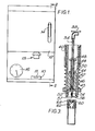
- the evacuating apparatus comprises a platform 10 on which to stand a bottle to be evacuated and an overhanging body portion 12 from which a plunger assembly projects downwardly, towards the platform.
- An operating lever projects forwardly from the front face of the body portion 12 and this lever 14 is manually operated.
- the apparatus is provided with a pressure gauge 16.
- the lever 14 is pivoted at 20 to a bracket 22 mounted to afixed vertical shaft 24.
- a piston-and-cylinder suction device 26 is mounted, the cylinder being pivoted to a fixed cradle at 28 and the piston being coupled to the rear end of the lever 14 by a pin 15 on the lever being engaged in an elongated slot 27 in the piston rod: a screw 29 is threaded through the end of the piston rod and is adjustable to determine the stroke which the suction device will execute.
- a U-shaped bracket 30 is slidably mounted on the shaft 24, the shaft being engaged in round holes formed in the upper and lower limbs of the bracket, which limbs are respectively above and below the fixed bracket 22.
- a return spring 32 acts between the bracket 22 and the upper limb of slidable bracket 30, to return the latter bracket to its normal position at the top of the shaft 24. Forwardly of its pivot point 20 the lever is pivotally coupled to the slidable bracket, at 33.
- the plunger assembly 13 is mounted to the front face of the bracket 30: the plunger 34 of this assembly projects out at the top and connects via an elbow connector 35 to a flexible pipe 36 leading from the suction outlet of the suction device 26: this pipe is branched at 37 so as to lead to the pressure gauge 16 also.
- An extension 38 projects from the slidable bracket 30 to over lie the elbow connector 35 and provide a stop, as will be described below.
- FIG. 3 shows the construction of the plunger assembly in more detail.
- a sleeve 40 is fixed to the front of the slidable bracket 30.
- a stainless steel, outer tube 42 is slidably guided within this sleeve 40, is provided with a collar 43 near its lower end and a spring 44 which acts between the collar 44 and the sleeve 40.
- An inner tube 46 of PTFE or similar material is fixed within the outer tube 42 and its lower end terminates just short of the lower end of the outer tube 42.
- the plunger 34 extends through a longitudinal bore in the inner, PTFE tube and a collar 50 which rests on the top end of the inner tube 46.
- a collar 48 is fixed to the plunger 34 some distance above collar 50 and a spring 49,which may comprise a body of elastomeric material, acts between these two collars.
- the lower end of the inner tube 46 has its through- bore enlarged in diameter to accomodate another collar 52 fixed to the plunger a short distance above its bottom end. It will be noted that a sealing 0-ring is provided where each of the collars 50,52 seats against the opposite ends of the inner, PTFE tube.
- the bottom end of the plunger 34 is formed with four longitudinal slots 54, spaced equally around its circumference, and a screw 56 is threaded into the end of the plunger, but not so far as to close the slots: the screw 56 has its head formed with two slots 57 across it at right angles.
- the operating lever 14 is urged to an upper position, by the return spring urging the slidable bracket to the top of the shaft 24.
- the spring element 49 of the plunger assembly urges the plunger upwardly within this assembly such that its lower collar 52 is pressed against the internal shoulder of the inner, PTFE tube 46 and the bottom end of the plunger (i.e. the head of the screw 56) is approximately level with the bottom end of the outer, stainless steel tube 42.
- the bottle to be evacuated (complete with its sealing cap 60) is placed in position, by tilting its top towards the apparatus, engaging its cap within the end of the outer tube 42 and so that the top end of the cap-bore receives the plunger-end, and then swinging the bottom end of the bottle in towards the apparatus and so as to engage into the slot 11 of the platform 10, from the front and rest against the back of this slot.
- the operating lever 14 is moved downwards by hand: firstly this lowers the slidable bracket 40 slightly and with it the plunger assembly 13 so that the lower end of the inner, PTFE tube is pressed onto the top of the rubber cap 60 of the bottle, and also the bottom end of the plunger 34 (i.e.
- the screw 56 is brought down (without the plunger yet moving relative to the PTFE tube 46) so as to press the plug 62 of the cap 60 inwards and to displace this plug into its second or intermediate position.
- the plug 62 is now engaged with its diaphragm 64 in the middle one of the three grooves formed in the through-bore of its cap 60, instead of being inr the upper groove (where it sealed the cap). In its middle position, there is clearance all around the plug for air to be extracted.
- the lever 14 continues to-be moved downwards, its pin 15 will come into contact with the adjusting screw 29 of the suction piston and then drive the suction device through a stroke.
- Suction will thus be applied through pipe 36 and through the plunger 34 and its bottom-end slots 54 to the space within the inner tube 46 at its bootom end.
- the suction is applied from here, through the cap 60 and to the interior of the bottle to evacuate this.
- the bracket or stop 38 comes into contact with the elbow connector 35 on the top of the plunger 34, and presses the plunger downwards, against the bias of the spring element 49, to displace the plug 62 of the cap downwards and into its final, sealing position within the cap.
- the diaphragm 64 of the plug is now engaged into the lowest of the three grooves in the cap and the plug body is tightly engaged into the lowermost and smalest-diameter portion of the through-bore in the cap.
- the return spring 32 returns the slidable bracket and the plunger assembly to their original, upwards positions and the suction device piston to its original lowered position. Also the spring element 49 returns the plunger 34 to its original position within the PTFE tube 46 (i.e. with its collar 52 against the shoulder within the PTFE tube). The evacuated bottle can now be removed for use.
- the pressure gauge 16 will indicate the level of vacuum being created within the bottle during the suction stroke.
- the platform 10 may be made removable so that it can be replaced by alternative platforms of e.g. greater height and/or with wider slots 11 to suit bottles or containers of different heights or diameters.
Landscapes
- Chemical & Material Sciences (AREA)
- Dispersion Chemistry (AREA)
- Engineering & Computer Science (AREA)
- Mechanical Engineering (AREA)
- Sealing Of Jars (AREA)
- Vacuum Packaging (AREA)
- Closures For Containers (AREA)
Applications Claiming Priority (2)
| Application Number | Priority Date | Filing Date | Title |
|---|---|---|---|
| GB8520785 | 1985-08-20 | ||
| GB8520785A GB2179334B (en) | 1985-08-20 | 1985-08-20 | Evacuating apparatus |
Publications (1)
| Publication Number | Publication Date |
|---|---|
| EP0211686A1 true EP0211686A1 (fr) | 1987-02-25 |
Family
ID=10584016
Family Applications (1)
| Application Number | Title | Priority Date | Filing Date |
|---|---|---|---|
| EP86306364A Withdrawn EP0211686A1 (fr) | 1985-08-20 | 1986-08-18 | Dispositif de mise sous vide |
Country Status (5)
| Country | Link |
|---|---|
| US (1) | US4699190A (fr) |
| EP (1) | EP0211686A1 (fr) |
| AU (1) | AU576971B2 (fr) |
| GB (1) | GB2179334B (fr) |
| ZA (1) | ZA866039B (fr) |
Cited By (1)
| Publication number | Priority date | Publication date | Assignee | Title |
|---|---|---|---|---|
| EP3009357A3 (fr) * | 2014-10-14 | 2016-06-22 | Sunbeam Products, Inc. | Scelleuse sous vide avec tête réglable |
Families Citing this family (15)
| Publication number | Priority date | Publication date | Assignee | Title |
|---|---|---|---|---|
| US4881580A (en) * | 1986-02-03 | 1989-11-21 | Hughes Aircraft Company | Fixture adapted for evacuating and filling heat pipes and similar closed vessels |
| US4800931A (en) * | 1987-01-28 | 1989-01-31 | Stephen Petkovsek | Combination pressure producing and evacuation testing device |
| US5031785A (en) * | 1990-02-14 | 1991-07-16 | Epicurean International Corp. | Combination vacuum/pressure pump and valve stopper for food or drink containers |
| CA2056792C (fr) * | 1991-12-02 | 2002-07-16 | George Douglas Campbell | Dispositif d'ouverture de robinet |
| US5421380A (en) * | 1994-03-16 | 1995-06-06 | Campbell; Michael C. | Gas tank evacuator |
| US6199436B1 (en) * | 1999-06-09 | 2001-03-13 | Electric Power Research Institute, Inc. | Method and apparatus for field fluid sampling and dissolved gas analysis |
| DE10149435C1 (de) * | 2001-10-06 | 2003-06-18 | Sarstedt Ag & Co | Evakuierungseinrichtung zur Erzeugung eines Vakuums in einem Blutentnahmeröhrchen |
| US20050011567A1 (en) * | 2003-07-16 | 2005-01-20 | Hotmon International Corporation | Vacuum sealing-structure for heat-sinking conduit/chamber |
| TWI245875B (en) * | 2003-07-18 | 2005-12-21 | Huei-Chiun Shiu | Method and apparatus for removing non-condensable vapor within heat pipe |
| ATE396753T1 (de) | 2005-12-05 | 2008-06-15 | Hersill S L | Medizinisches absauggerät |
| US9808842B2 (en) | 2011-08-18 | 2017-11-07 | Justrite Manufacturing Company, L.L.C. | Gas evacuation system with counter |
| US9845232B2 (en) | 2014-02-17 | 2017-12-19 | Justrite Manufacturing Company, Llc | Puncturing device for aerosol containers |
| US9993764B2 (en) | 2014-04-01 | 2018-06-12 | Justrite Manufacturing Company, Llc | Filter for a propellant gas evacuation system |
| US9827528B2 (en) | 2015-04-01 | 2017-11-28 | Justrite Manufacturing Company, Llc | Filter for a propellant gas evacuation system |
| USD798918S1 (en) | 2015-11-25 | 2017-10-03 | Justrite Manufacturing Company, L.L.C. | Shield for puncturing device |
Citations (1)
| Publication number | Priority date | Publication date | Assignee | Title |
|---|---|---|---|---|
| GB838858A (en) * | 1957-10-01 | 1960-06-22 | Raffaele Pirro | Apparatus for the closure of bottles under high vacuum |
Family Cites Families (6)
| Publication number | Priority date | Publication date | Assignee | Title |
|---|---|---|---|---|
| US2303766A (en) * | 1939-08-19 | 1942-12-01 | Scherbak Hermann | Vacuum sealing device |
| DE814711C (de) * | 1948-10-02 | 1951-12-03 | Heinrich Fischer | Vorrichtung zum Verschliessen von Gefaessen mittels Vakuum |
| US3313444A (en) * | 1964-11-19 | 1967-04-11 | Katell Abraham | Combined container cover and vacuum pump |
| GB2008200B (en) * | 1977-11-09 | 1982-10-20 | Emerit Andre A C | Source of vacuum and device for creating and maintaining anegative pressure in an enclosure |
| DE2821852C3 (de) * | 1978-05-19 | 1980-12-18 | Zyliss Zysset Ag, Lyss (Schweiz) | Gerät zur Aufbewahrung von verderblichen Waren |
| US4543980A (en) * | 1983-10-13 | 1985-10-01 | Sanden John A V D | Valve for pressurized containers |
-
1985
- 1985-08-20 GB GB8520785A patent/GB2179334B/en not_active Expired
-
1986
- 1986-08-12 ZA ZA866039A patent/ZA866039B/xx unknown
- 1986-08-14 AU AU61180/86A patent/AU576971B2/en not_active Ceased
- 1986-08-14 US US06/896,751 patent/US4699190A/en not_active Expired - Fee Related
- 1986-08-18 EP EP86306364A patent/EP0211686A1/fr not_active Withdrawn
Patent Citations (1)
| Publication number | Priority date | Publication date | Assignee | Title |
|---|---|---|---|---|
| GB838858A (en) * | 1957-10-01 | 1960-06-22 | Raffaele Pirro | Apparatus for the closure of bottles under high vacuum |
Cited By (1)
| Publication number | Priority date | Publication date | Assignee | Title |
|---|---|---|---|---|
| EP3009357A3 (fr) * | 2014-10-14 | 2016-06-22 | Sunbeam Products, Inc. | Scelleuse sous vide avec tête réglable |
Also Published As
| Publication number | Publication date |
|---|---|
| AU6118086A (en) | 1987-02-26 |
| US4699190A (en) | 1987-10-13 |
| ZA866039B (en) | 1987-03-25 |
| GB8520785D0 (en) | 1985-09-25 |
| GB2179334A (en) | 1987-03-04 |
| GB2179334B (en) | 1989-08-02 |
| AU576971B2 (en) | 1988-09-08 |
Similar Documents
| Publication | Publication Date | Title |
|---|---|---|
| US4699190A (en) | Evacuating apparatus | |
| US7549972B2 (en) | Tool for extracting vitreous samples from an eye | |
| CN1654820B (zh) | 手动泵机构和输送系统 | |
| EP0076239B1 (fr) | Seringue pour biopsie hypodermique comportant un piston à retour automatique | |
| US5873887A (en) | Blood sampling device | |
| US3834387A (en) | Breech loaded syringe with deformable piston | |
| JP2761436B2 (ja) | 流体流れチェックバルブ | |
| JP2803767B2 (ja) | 液体曝気装置 | |
| US4732162A (en) | Automatic and position-sensitive syringe and method for nonaspirating or aspirating obtaining of blood samples | |
| US4217798A (en) | Automated test tube stopper remover | |
| EP1219242A1 (fr) | Dispositif d'echantillonnage de liquides organiques | |
| US11320345B2 (en) | Adjustable volume sampling system (AVSS) | |
| US3834240A (en) | Apparatus for drawing liquids into, and expelling liquids from, a pipette or the like | |
| US3955341A (en) | Apparatus for screwing caps on containers | |
| JPS62447B2 (fr) | ||
| EP0737515B1 (fr) | Pipette à plusieurs phases de fonctionnement | |
| US5015237A (en) | Pneumatic powered animal injector | |
| CN212031027U (zh) | 一种医疗检测用体液提取装置 | |
| EP0667112A1 (fr) | Casse-noix hydraulique | |
| US2700497A (en) | Bottle stoppering machine | |
| AU2002301337B2 (en) | Apparatus for forming a vacuum in a blood tube | |
| US3972116A (en) | Shear | |
| WO1988007351A1 (fr) | Tube collecteur et appareil servant a faire le vide au prealable | |
| RU2104042C1 (ru) | Медицинское отсасывающее устройство | |
| JPH02110323A (ja) | ピペット装置 |
Legal Events
| Date | Code | Title | Description |
|---|---|---|---|
| PUAI | Public reference made under article 153(3) epc to a published international application that has entered the european phase |
Free format text: ORIGINAL CODE: 0009012 |
|
| AK | Designated contracting states |
Kind code of ref document: A1 Designated state(s): AT BE CH DE FR IT LI LU NL SE |
|
| 17P | Request for examination filed |
Effective date: 19870821 |
|
| 17Q | First examination report despatched |
Effective date: 19880708 |
|
| STAA | Information on the status of an ep patent application or granted ep patent |
Free format text: STATUS: THE APPLICATION IS DEEMED TO BE WITHDRAWN |
|
| 18D | Application deemed to be withdrawn |
Effective date: 19890630 |
|
| RIN1 | Information on inventor provided before grant (corrected) |
Inventor name: BATES, WILLIAM THOMAS DENNIS |