EP0211695A1 - Dispositifs pulvérisateurs pour peintures - Google Patents
Dispositifs pulvérisateurs pour peintures Download PDFInfo
- Publication number
- EP0211695A1 EP0211695A1 EP86306534A EP86306534A EP0211695A1 EP 0211695 A1 EP0211695 A1 EP 0211695A1 EP 86306534 A EP86306534 A EP 86306534A EP 86306534 A EP86306534 A EP 86306534A EP 0211695 A1 EP0211695 A1 EP 0211695A1
- Authority
- EP
- European Patent Office
- Prior art keywords
- cavity
- cross
- container
- supply tube
- fluid supply
- Prior art date
- Legal status (The legal status is an assumption and is not a legal conclusion. Google has not performed a legal analysis and makes no representation as to the accuracy of the status listed.)
- Withdrawn
Links
- 239000003973 paint Substances 0.000 title claims abstract description 27
- 238000005507 spraying Methods 0.000 title claims abstract description 13
- 239000012530 fluid Substances 0.000 claims abstract description 17
- 239000002991 molded plastic Substances 0.000 claims abstract description 4
- 239000011344 liquid material Substances 0.000 claims description 15
- 239000000463 material Substances 0.000 claims description 13
- 210000001364 upper extremity Anatomy 0.000 claims description 9
- 210000003141 lower extremity Anatomy 0.000 claims description 5
- 230000000630 rising effect Effects 0.000 claims description 4
- 230000003247 decreasing effect Effects 0.000 claims description 3
- 230000000149 penetrating effect Effects 0.000 claims description 3
- 101100298222 Caenorhabditis elegans pot-1 gene Proteins 0.000 abstract description 9
- 239000007788 liquid Substances 0.000 abstract description 5
- -1 polyethylene Polymers 0.000 abstract description 5
- 239000004698 Polyethylene Substances 0.000 abstract description 4
- 229920000573 polyethylene Polymers 0.000 abstract description 4
- 238000002347 injection Methods 0.000 abstract description 3
- 239000007924 injection Substances 0.000 abstract description 3
- 210000002969 egg yolk Anatomy 0.000 description 6
- 229920002678 cellulose Polymers 0.000 description 4
- 239000001913 cellulose Substances 0.000 description 4
- XAGFODPZIPBFFR-UHFFFAOYSA-N aluminium Chemical compound [Al] XAGFODPZIPBFFR-UHFFFAOYSA-N 0.000 description 3
- 229910052782 aluminium Inorganic materials 0.000 description 3
- 239000004411 aluminium Substances 0.000 description 3
- 239000007921 spray Substances 0.000 description 3
- 239000011248 coating agent Substances 0.000 description 2
- 239000008199 coating composition Substances 0.000 description 2
- 238000000576 coating method Methods 0.000 description 2
- 238000001746 injection moulding Methods 0.000 description 2
- 239000004033 plastic Substances 0.000 description 2
- 229920003023 plastic Polymers 0.000 description 2
- 229910000838 Al alloy Inorganic materials 0.000 description 1
- 239000004743 Polypropylene Substances 0.000 description 1
- 229920001577 copolymer Polymers 0.000 description 1
- 230000008878 coupling Effects 0.000 description 1
- 238000010168 coupling process Methods 0.000 description 1
- 238000005859 coupling reaction Methods 0.000 description 1
- 230000000694 effects Effects 0.000 description 1
- 210000003414 extremity Anatomy 0.000 description 1
- 239000003517 fume Substances 0.000 description 1
- 239000007769 metal material Substances 0.000 description 1
- 239000003960 organic solvent Substances 0.000 description 1
- 229920001155 polypropylene Polymers 0.000 description 1
- 230000009467 reduction Effects 0.000 description 1
- 238000000926 separation method Methods 0.000 description 1
- 238000000935 solvent evaporation Methods 0.000 description 1
- 239000000126 substance Substances 0.000 description 1
Images

Classifications
-
- B—PERFORMING OPERATIONS; TRANSPORTING
- B05—SPRAYING OR ATOMISING IN GENERAL; APPLYING FLUENT MATERIALS TO SURFACES, IN GENERAL
- B05B—SPRAYING APPARATUS; ATOMISING APPARATUS; NOZZLES
- B05B7/00—Spraying apparatus for discharge of liquids or other fluent materials from two or more sources, e.g. of liquid and air, of powder and gas
- B05B7/24—Spraying apparatus for discharge of liquids or other fluent materials from two or more sources, e.g. of liquid and air, of powder and gas with means, e.g. a container, for supplying liquid or other fluent material to a discharge device
- B05B7/2402—Apparatus to be carried on or by a person, e.g. by hand; Apparatus comprising containers fixed to the discharge device
- B05B7/2405—Apparatus to be carried on or by a person, e.g. by hand; Apparatus comprising containers fixed to the discharge device using an atomising fluid as carrying fluid for feeding, e.g. by suction or pressure, a carried liquid from the container to the nozzle
- B05B7/2408—Apparatus to be carried on or by a person, e.g. by hand; Apparatus comprising containers fixed to the discharge device using an atomising fluid as carrying fluid for feeding, e.g. by suction or pressure, a carried liquid from the container to the nozzle characterised by the container or its attachment means to the spray apparatus
Definitions
- the invention relates to paint spraying equipment such as used In the car refinishing Industry.
- Car paint finishes are commonly replaced or renewed by their owners either to change a vehicle's colour or to provide a new finish to palntwork which has suffered damage, discolouration and general wear and tear.
- paint refinishing operations have employed cellulose paint finishes which are sprayed from a conventional air spray gun and left to dry In the air to a hard finish.
- Chem I cally-curring finishes have gradually replaced cellulose paint finishes since Introduction of the former some years ago.
- These finishes comprise materials which cure by chemical change rather than simply by solvent evaporation and offer the advantage of speedy refinishing, hard surface finish and reductions in the level of fumes and vapours compared to that derived from conventional paint vehicles, such as the volatile organic solvents used In cellulose paints.
- Spraying equipment used In car refinishing usually comprises a nozzled gun head supplied by Venturi effect via a tube from a reservoir of paint or other liquid coating composition contained In a cylindrical cup or pot to which the gun head Is mounted.
- the supply tube Is disposed In the cavity of the cup with its lowermost end opening within a body of the paint.
- the tube Is bent towards one side of the cavity so that when the cup is tipped with Its normally vertical axis no longer vertical, the risk that the level falls beneath the tube opening Is minimized.
- the tube Is of course, also sufficiently long that Its opening is as close as possible to the base of the cup. However, there is commonly sufficient clearance that a fitter body of some kind can be mounted to the terminus of the supply tube In the clearance space.
- the above practice obviously reduces the volume of paint or other liquid which must remain In the cup to allow spraying to continue.
- the minimum required volume is obviously important in as much as it determines the amount of paint required to be charged to the cup In excess of that required by the surface to be coated. The amount has particular significance In the context of chemically-curing surface coating materials where the resulting materials wastage would otherwise Involve a real level of unnecessary cost.
- an apparatus for spraying paint or other liquid material which apparatus comprises a container for said liquid material, said container having an access opening to Its cavity for charging of said liquid material thereto and a removable closure member for said opening, and a fluid supply tube penetrating said container and having an end opening Into said cavity and so disposed as in use to be adjacent the bottom of a body of liquid contained In said cavity, characterized
- said container has a non-uniform cross-sectional area decreasing to a minimum In the viclnity of the fluld supply tube open end whereby the ratio between volume and depth of liquid material in the container cavity when the level of said liquid material Just reaches the fluid supply tube open end Is preferably minimized but In any event reduced compared to a uniform cross-sectioned container of the same maximum cross-section.
- the liquid material container will in general take the form of a cavity-defining member supported within a conventional paint sprayer container of, for example, right circular cylindrical form and made from metallic material such as aluminium or aluminium alloy.
- a conventional sprayer container may, of course, be entirely omitted In some embodiments of the invention.
- the form of arrangement Just referred to Is much preferred since a simple accessory member, for example, of moulded plastics material, can easily and economically be made to be Inserted Into conventional spray containers so that the existing equipment can be fully relied on for Its proven design of closure and fluid supply tube arrangements.
- the apparatus comprises a main container of preferably right circular cylindrical form, the main container having a top equipped with a closure member removable to allow access to the container cavity and a base, a vessel supported within the main container cavity and having a cross-section at its upper extremity preferably approximating that of the adjacent cavity-defining walls of the main container, the vessel having a smaller cross-sectional area at the lower extremity of the vessel.
- the reduced cross-sectional area at the lower extremity of the vessel I (or the minimum area) will I conveniently be not more than 45% of the cross-sectional area of the container at Its base.
- the ratio will generally be 35% or less (eg. not more than 25%), preferably less than 20% (eg 15% or less, most preferably a figure in the range from 8% to 14% such 10% approximately).
- the reduced cross-sectional area may, for example, be a circular area not more than 25 or 30 times (eg 10 to 20 times) such as about 12 to 25 times larger In diameter than the opening of the fluid supply tube (typically about 15 times larger), the circular area being measured at the level of a body of liquid Just covering the tube opening.
- the Internally supported vessel may convenlently be made of a coating composition-resistant plastics material such as a polyethylene or polypropylene (or copolymer).
- a coating composition-resistant plastics material such as a polyethylene or polypropylene (or copolymer).
- the vessel is most conveniently made by Injection moulding and thus Its material will preferably be selected with this In mind.
- the vessel should normally be self-supporting In use conditions when charged with a body of paint so as to be dimensionally and configurationally stable, at least at the lower extremity.
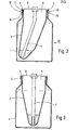
- the apparatus shown in the drawings comprises a 106mm Internal diameter aluminium pot 1 of right circular cylindrical form, as conventionally used In paint spraying equipment. Supported through the open top of the pot is a 39mm Internal diameter Injection moulded polyethylene vessel 2 having 1mm thick walls. The flanges 3 and 4 of the latter locate over the upper rim of pot 1, cut-out 15 being received over pot lugs 12. A conventional-type lid 6, also of aluminium, sealingly engages by a seal (not shown) the flange 4 of vessel 2. A 10mm Internal diameter fluid supply tube assembly 7 penetrates central opening 8 in lid 6 so as largely to reside In the cavity 5 of vessel 2 and is also conventional for use In paint spraying equipment.
- Vessel 2 has an external circular cross-section at Its upper end which Is approximately equal to the Internal cross-section of container or pot 1.
- the cross-section of vessel 2 reduces downwardly until I It Is a fraction of this value at the region of the end opening of tube 7, as will be evident from Figures 2 and 3 In particular.
- Vessel 2 Is configured to accommodate the bend In tube 7, as best seen In Figure 2.
- a yolk 9 is received over the top portion of the tube assembly 7 and Is located and restrained against rotation relative to the lid 6 and assembly 7 by diametrically opposed flats 13 of assembly 7 and cooperative parts of the yolk aperture, as will I be evident from Figure 1.
- Arms 10 of yolk 9 extend downwardly and Include slotted extremities 11 which engage lugs 12 of the container 1, the latter being fixed In the wall of pot 1 by heads of caps 20 present In both the Figure 1 and Figure 4 embodiments but Illustrated only In Figure 4.
- the lugs 12 are entered Into slots 1 1 by appropriate rotation of 11d 6, assembly 7 and yolk 9 relative to the pot 1, following which operation of cam lever 14 urges the yolk 9 upwardly by cooperation of Its rotating cam surfaces with those of the yolk.
- the volume of paint or other liquid material In the vessel 2 can, as will I be appreciated, reach a very low level (typically 4ml In the case of the apparatus shown In Figures 1 to 3), whilst remaining above the opening In tube 7. This enables spraying to be effected with little wastage of materials and thus no significant wasted expenditure.
- the vessel 2 has a front face inclined to the wall surface of container 1, It is thought that a vessel having a vertical I front wall I (ie generally parallel to the container 1 wall) will be easier to make by injection moulding. Such form Is therefore preferred and Is I lustrated in Figure 4 of the drawings in which as compared to Figures 1 to 3 like parts are designated by like reference numerals.
- the vessel 2 of Figures 1 to 3 is replaced by an alternative vessel of the same material but having an upper relatively thick wailed portion 19 of uniform right circular cylindrical form and a lower relatively thin walled portion 18 of non-uniform cross-section and Inclined axis.
- Portion 19 has an out-turned flange which seats upon and seals with the top rim of pot 1 In similar fashion to flange 4 of the apparatus shown In Figures 1 to 3 but has no counterpart to flange 3 shown In Figure 1.
- a recess 21 is formed at each of two diametrically opposed sides in the thickness of portion 19, recesses 21 cooperating with caps 20 of lugs 12 to support the polyethylene vessel within the cavity of pot 1 In similar fashion to the arrangement shown In Figures 1 to 3.
- Lower cylindrical vessel portion 18 has a flat circular base 22.
- the remainder of the portion 18 rises from base 22 as a wall which is perpendicular at 17 and increasingly obtusely angled relative to the base 22 with increasing angular separation from the perpendicular wall portion.
- two spaced parallel axes penetrate the centre of base 22 on the one hand and the centre of the circular open top of portion 19 on the other.
- Tube 7 Is received In the vessel In similar orientation with respect to the vessel as that depicted In Figures 1 to 3.
- Base 22 has an area of approximately 25% of the I nterna I area of the opening Into thick walled portion 19 of vessel 2, the latter conveniently being of the order of 50 sq.cm.
- the invention Includes within its scope a self-supporting container for paint and the like comprising a moulded plastics material member defining a cavity within cylindrical side walls which rise from a generally circular or eliptical flat base, the member having an outwardly flanged lip formed at Its upper extremity and defining a generally circular opening Into the cavity, the base having a surface area Internally of the cavity equal to less than 35% of the cross-sectional area of the circular opening defined at the upper extremity of the moulded member and the cylindrical walls rising perpendicularly from the base at a first Junction of walls and base and rising with an obtuseness of angle at other Junctions which Increases with spacing from said first Junction.
- Such a container may, for example, be Injection moulded, the cylindrical side walls Including an upper portion adjacent the upper extremity of the moulded member, said portion having a uniform cross-section and being moulded with a pair of diametrically opposed location recesses formed In the thickness of the plastic material of the moulded member on the exterior thereof, the base having a surface area Internal ly of the cavity equal to 15% to 25% of the cross-sectional area of the circular opening defined at the upper extremity of the moulded member.
Landscapes
- Nozzles (AREA)
- Photographic Developing Apparatuses (AREA)
- Steering-Linkage Mechanisms And Four-Wheel Steering (AREA)
- Toys (AREA)
Applications Claiming Priority (2)
| Application Number | Priority Date | Filing Date | Title |
|---|---|---|---|
| GB8521216 | 1985-08-23 | ||
| GB858521216A GB8521216D0 (en) | 1985-08-23 | 1985-08-23 | Paint spraying equipment |
Publications (1)
| Publication Number | Publication Date |
|---|---|
| EP0211695A1 true EP0211695A1 (fr) | 1987-02-25 |
Family
ID=10584262
Family Applications (1)
| Application Number | Title | Priority Date | Filing Date |
|---|---|---|---|
| EP86306534A Withdrawn EP0211695A1 (fr) | 1985-08-23 | 1986-08-22 | Dispositifs pulvérisateurs pour peintures |
Country Status (6)
| Country | Link |
|---|---|
| EP (1) | EP0211695A1 (fr) |
| DK (1) | DK400286A (fr) |
| FI (1) | FI863391A7 (fr) |
| GB (2) | GB8521216D0 (fr) |
| NO (1) | NO863395L (fr) |
| ZA (1) | ZA866410B (fr) |
Cited By (8)
| Publication number | Priority date | Publication date | Assignee | Title |
|---|---|---|---|---|
| WO1995007762A1 (fr) * | 1993-09-13 | 1995-03-23 | Michael Andersson | Dispositif de pulverisation de liquide a air comprime |
| GB2333504B (en) * | 1998-01-21 | 2002-10-23 | Eastman Kodak Co | Container |
| WO2003045575A1 (fr) * | 2001-11-14 | 2003-06-05 | Martin Ruda | Recipient de pistolet-pulverisateur pourvu d'une piece interne solide |
| US8297536B2 (en) | 2002-12-10 | 2012-10-30 | Martin Ruda | Spray gun container and method of producing a cover |
| CN103285469A (zh) * | 2012-02-22 | 2013-09-11 | 北京天衡药物研究院 | 醋酸去氨加压素鼻喷剂 |
| CN103285471A (zh) * | 2012-02-22 | 2013-09-11 | 北京天衡药物研究院 | 维生素b12鼻喷剂 |
| WO2021114942A1 (fr) * | 2019-12-13 | 2021-06-17 | 苏州宝时得电动工具有限公司 | Pulvérisateur |
| JP2021121431A (ja) * | 2016-01-15 | 2021-08-26 | スリーエム イノベイティブ プロパティズ カンパニー | ハンドヘルド式スプレーガンのコネクタシステム |
Families Citing this family (2)
| Publication number | Priority date | Publication date | Assignee | Title |
|---|---|---|---|---|
| US5727708A (en) * | 1996-11-13 | 1998-03-17 | Erickson Tool Design, Inc. | Form fit throw-away liner for a reusable paint bucket including roller grate |
| GB2333514B (en) * | 1998-01-21 | 2002-04-24 | Eastman Kodak Co | Mounting arrangement |
Citations (4)
| Publication number | Priority date | Publication date | Assignee | Title |
|---|---|---|---|---|
| US3136486A (en) * | 1962-06-21 | 1964-06-09 | Melford H Docken | Spray gun for use with a disposable container |
| US3401842A (en) * | 1966-11-28 | 1968-09-17 | Betty L Morrison | Combination paint cup and filler for spray guns |
| US3507309A (en) * | 1967-07-07 | 1970-04-21 | Harold D Johnson | Sprayer for hydrocarbon-containing liquids |
| US4429835A (en) * | 1980-11-17 | 1984-02-07 | Inge Brugger | Spray-diffuser |
Family Cites Families (1)
| Publication number | Priority date | Publication date | Assignee | Title |
|---|---|---|---|---|
| US3567129A (en) * | 1969-06-23 | 1971-03-02 | G G Benjamin & Co Pty Ltd | Spraying devices |
-
1985
- 1985-08-23 GB GB858521216A patent/GB8521216D0/en active Pending
-
1986
- 1986-08-22 EP EP86306534A patent/EP0211695A1/fr not_active Withdrawn
- 1986-08-22 FI FI863391A patent/FI863391A7/fi not_active Application Discontinuation
- 1986-08-22 GB GB8620497A patent/GB2179275B/en not_active Expired - Lifetime
- 1986-08-22 ZA ZA866410A patent/ZA866410B/xx unknown
- 1986-08-22 DK DK400286A patent/DK400286A/da unknown
- 1986-08-25 NO NO863395A patent/NO863395L/no unknown
Patent Citations (4)
| Publication number | Priority date | Publication date | Assignee | Title |
|---|---|---|---|---|
| US3136486A (en) * | 1962-06-21 | 1964-06-09 | Melford H Docken | Spray gun for use with a disposable container |
| US3401842A (en) * | 1966-11-28 | 1968-09-17 | Betty L Morrison | Combination paint cup and filler for spray guns |
| US3507309A (en) * | 1967-07-07 | 1970-04-21 | Harold D Johnson | Sprayer for hydrocarbon-containing liquids |
| US4429835A (en) * | 1980-11-17 | 1984-02-07 | Inge Brugger | Spray-diffuser |
Cited By (10)
| Publication number | Priority date | Publication date | Assignee | Title |
|---|---|---|---|---|
| WO1995007762A1 (fr) * | 1993-09-13 | 1995-03-23 | Michael Andersson | Dispositif de pulverisation de liquide a air comprime |
| GB2333504B (en) * | 1998-01-21 | 2002-10-23 | Eastman Kodak Co | Container |
| WO2003045575A1 (fr) * | 2001-11-14 | 2003-06-05 | Martin Ruda | Recipient de pistolet-pulverisateur pourvu d'une piece interne solide |
| US8297536B2 (en) | 2002-12-10 | 2012-10-30 | Martin Ruda | Spray gun container and method of producing a cover |
| CN103285469A (zh) * | 2012-02-22 | 2013-09-11 | 北京天衡药物研究院 | 醋酸去氨加压素鼻喷剂 |
| CN103285471A (zh) * | 2012-02-22 | 2013-09-11 | 北京天衡药物研究院 | 维生素b12鼻喷剂 |
| JP2021121431A (ja) * | 2016-01-15 | 2021-08-26 | スリーエム イノベイティブ プロパティズ カンパニー | ハンドヘルド式スプレーガンのコネクタシステム |
| JP7057007B2 (ja) | 2016-01-15 | 2022-04-19 | スリーエム イノベイティブ プロパティズ カンパニー | ハンドヘルド式スプレーガンのコネクタシステム |
| US11413636B2 (en) | 2016-01-15 | 2022-08-16 | 3M Innovative Properties Company | Connector system for hand-held spray guns |
| WO2021114942A1 (fr) * | 2019-12-13 | 2021-06-17 | 苏州宝时得电动工具有限公司 | Pulvérisateur |
Also Published As
| Publication number | Publication date |
|---|---|
| DK400286A (da) | 1987-02-24 |
| FI863391A0 (fi) | 1986-08-22 |
| DK400286D0 (da) | 1986-08-22 |
| GB8521216D0 (en) | 1985-10-02 |
| FI863391L (fi) | 1987-02-24 |
| NO863395D0 (no) | 1986-08-25 |
| GB2179275B (en) | 1990-03-28 |
| GB8620497D0 (en) | 1986-10-01 |
| FI863391A7 (fi) | 1987-02-24 |
| GB2179275A (en) | 1987-03-04 |
| NO863395L (no) | 1987-02-24 |
| ZA866410B (en) | 1987-04-29 |
Similar Documents
| Publication | Publication Date | Title |
|---|---|---|
| US4832232A (en) | Spray gun vent | |
| EP0211695A1 (fr) | Dispositifs pulvérisateurs pour peintures | |
| US7387264B2 (en) | Asymmetrical spray nozzle with alignment notch | |
| US3381845A (en) | Disposable plastic container for spray guns | |
| US7757972B2 (en) | Conversion adapter for a fluid supply assembly | |
| EP1703989B1 (fr) | Ensemble adaptateur de type baionnette pour coupelle d'alimentation d'un pistolet pulverisateur | |
| US4405088A (en) | Adaptor for disposable cans for siphon-type spray paint guns | |
| US3990609A (en) | Attachment for paint spray gun systems | |
| US20040026450A1 (en) | Container for holding a product | |
| US5318314A (en) | Paint hopper assembly | |
| EP2877293B1 (fr) | Ensemble d'évents et réservoirs comprenant cet ensemble | |
| EP3319733B1 (fr) | Réservoirs de pistolet pulvérisateur, réceptacles et procédés d'utilisation | |
| MXPA96001721A (es) | Rociador accionado por gatillo. | |
| US4909409A (en) | Quick change spray paint receptacle apparatus | |
| US4056213A (en) | Pressurized dispenser for aqueous emulsion paints | |
| CA2561666A1 (fr) | Ensemble contenant et couvercle nouveau | |
| US3119528A (en) | Spraying device for retouching faded paint | |
| EP0379792A2 (fr) | Unité de pompe jetable | |
| JPH091003A (ja) | 2成分加圧供給システム | |
| US5249715A (en) | Dispensing container with an optionally removable insert in the neck of the container | |
| JPS6427659A (en) | Paint container for spray gun | |
| CN209362894U (zh) | 一种达克罗涂覆机用浸涂设备 | |
| US3934760A (en) | Retractable and vented pouring spout | |
| JPS6027478Y2 (ja) | トリガ−式噴霧器 | |
| JPS6034993Y2 (ja) | 加湿器 |
Legal Events
| Date | Code | Title | Description |
|---|---|---|---|
| PUAI | Public reference made under article 153(3) epc to a published international application that has entered the european phase |
Free format text: ORIGINAL CODE: 0009012 |
|
| AK | Designated contracting states |
Kind code of ref document: A1 Designated state(s): AT BE CH DE FR GB IT LI LU NL SE |
|
| STAA | Information on the status of an ep patent application or granted ep patent |
Free format text: STATUS: THE APPLICATION IS DEEMED TO BE WITHDRAWN |
|
| 18D | Application deemed to be withdrawn |
Effective date: 19870826 |