EP0211697A1 - Selbstzentrierendes Ausrücklager mit einem radial elastischen Sprengring für eine Kupplung - Google Patents
Selbstzentrierendes Ausrücklager mit einem radial elastischen Sprengring für eine Kupplung Download PDFInfo
- Publication number
- EP0211697A1 EP0211697A1 EP86400181A EP86400181A EP0211697A1 EP 0211697 A1 EP0211697 A1 EP 0211697A1 EP 86400181 A EP86400181 A EP 86400181A EP 86400181 A EP86400181 A EP 86400181A EP 0211697 A1 EP0211697 A1 EP 0211697A1
- Authority
- EP
- European Patent Office
- Prior art keywords
- bearing
- washer
- rotating ring
- sleeve
- stop
- Prior art date
- Legal status (The legal status is an assumption and is not a legal conclusion. Google has not performed a legal analysis and makes no representation as to the accuracy of the status listed.)
- Withdrawn
Links
- 230000007246 mechanism Effects 0.000 claims description 6
- 230000009471 action Effects 0.000 claims description 5
- 230000001154 acute effect Effects 0.000 claims description 3
- 238000005096 rolling process Methods 0.000 claims description 3
- 230000005489 elastic deformation Effects 0.000 description 6
- 210000005069 ears Anatomy 0.000 description 4
- 229940082150 encore Drugs 0.000 description 3
- 239000000463 material Substances 0.000 description 3
- 230000000694 effects Effects 0.000 description 2
- 238000012423 maintenance Methods 0.000 description 2
- 239000002184 metal Substances 0.000 description 2
- 230000002093 peripheral effect Effects 0.000 description 2
- 239000013641 positive control Substances 0.000 description 2
- 238000007493 shaping process Methods 0.000 description 2
- 240000008042 Zea mays Species 0.000 description 1
- 230000008859 change Effects 0.000 description 1
- 230000000295 complement effect Effects 0.000 description 1
- 229920001971 elastomer Polymers 0.000 description 1
- 239000000806 elastomer Substances 0.000 description 1
- 238000005530 etching Methods 0.000 description 1
- 239000004519 grease Substances 0.000 description 1
- 238000010438 heat treatment Methods 0.000 description 1
- 238000003780 insertion Methods 0.000 description 1
- 230000037431 insertion Effects 0.000 description 1
- 238000009434 installation Methods 0.000 description 1
- 238000005461 lubrication Methods 0.000 description 1
- 230000014759 maintenance of location Effects 0.000 description 1
- 210000000056 organ Anatomy 0.000 description 1
- 230000002085 persistent effect Effects 0.000 description 1
- 230000036316 preload Effects 0.000 description 1
- 230000009467 reduction Effects 0.000 description 1
- 230000001105 regulatory effect Effects 0.000 description 1
- 238000007789 sealing Methods 0.000 description 1
Images

Classifications
-
- F—MECHANICAL ENGINEERING; LIGHTING; HEATING; WEAPONS; BLASTING
- F16—ENGINEERING ELEMENTS AND UNITS; GENERAL MEASURES FOR PRODUCING AND MAINTAINING EFFECTIVE FUNCTIONING OF MACHINES OR INSTALLATIONS; THERMAL INSULATION IN GENERAL
- F16D—COUPLINGS FOR TRANSMITTING ROTATION; CLUTCHES; BRAKES
- F16D23/00—Details of mechanically-actuated clutches not specific for one distinct type
- F16D23/12—Mechanical clutch-actuating mechanisms arranged outside the clutch as such
- F16D23/14—Clutch-actuating sleeves or bearings; Actuating members directly connected to clutch-actuating sleeves or bearings
-
- F—MECHANICAL ENGINEERING; LIGHTING; HEATING; WEAPONS; BLASTING
- F16—ENGINEERING ELEMENTS AND UNITS; GENERAL MEASURES FOR PRODUCING AND MAINTAINING EFFECTIVE FUNCTIONING OF MACHINES OR INSTALLATIONS; THERMAL INSULATION IN GENERAL
- F16D—COUPLINGS FOR TRANSMITTING ROTATION; CLUTCHES; BRAKES
- F16D23/00—Details of mechanically-actuated clutches not specific for one distinct type
- F16D23/12—Mechanical clutch-actuating mechanisms arranged outside the clutch as such
- F16D23/14—Clutch-actuating sleeves or bearings; Actuating members directly connected to clutch-actuating sleeves or bearings
- F16D23/142—Clutch-actuating sleeves or bearings; Actuating members directly connected to clutch-actuating sleeves or bearings with a resilient member acting radially between the bearing and its guide means
-
- F—MECHANICAL ENGINEERING; LIGHTING; HEATING; WEAPONS; BLASTING
- F16—ENGINEERING ELEMENTS AND UNITS; GENERAL MEASURES FOR PRODUCING AND MAINTAINING EFFECTIVE FUNCTIONING OF MACHINES OR INSTALLATIONS; THERMAL INSULATION IN GENERAL
- F16C—SHAFTS; FLEXIBLE SHAFTS; ELEMENTS OR CRANKSHAFT MECHANISMS; ROTARY BODIES OTHER THAN GEARING ELEMENTS; BEARINGS
- F16C19/00—Bearings with rolling contact, for exclusively rotary movement
- F16C19/02—Bearings with rolling contact, for exclusively rotary movement with bearing balls essentially of the same size in one or more circular rows
- F16C19/14—Bearings with rolling contact, for exclusively rotary movement with bearing balls essentially of the same size in one or more circular rows for both radial and axial load
- F16C19/16—Bearings with rolling contact, for exclusively rotary movement with bearing balls essentially of the same size in one or more circular rows for both radial and axial load with a single row of balls
- F16C19/163—Bearings with rolling contact, for exclusively rotary movement with bearing balls essentially of the same size in one or more circular rows for both radial and axial load with a single row of balls with angular contact
-
- F—MECHANICAL ENGINEERING; LIGHTING; HEATING; WEAPONS; BLASTING
- F16—ENGINEERING ELEMENTS AND UNITS; GENERAL MEASURES FOR PRODUCING AND MAINTAINING EFFECTIVE FUNCTIONING OF MACHINES OR INSTALLATIONS; THERMAL INSULATION IN GENERAL
- F16C—SHAFTS; FLEXIBLE SHAFTS; ELEMENTS OR CRANKSHAFT MECHANISMS; ROTARY BODIES OTHER THAN GEARING ELEMENTS; BEARINGS
- F16C2361/00—Apparatus or articles in engineering in general
- F16C2361/43—Clutches, e.g. disengaging bearing
-
- F—MECHANICAL ENGINEERING; LIGHTING; HEATING; WEAPONS; BLASTING
- F16—ENGINEERING ELEMENTS AND UNITS; GENERAL MEASURES FOR PRODUCING AND MAINTAINING EFFECTIVE FUNCTIONING OF MACHINES OR INSTALLATIONS; THERMAL INSULATION IN GENERAL
- F16D—COUPLINGS FOR TRANSMITTING ROTATION; CLUTCHES; BRAKES
- F16D2300/00—Special features for couplings or clutches
- F16D2300/12—Mounting or assembling
Definitions
- the invention relates to a declutching stop, intended to disengage a clutch mechanism, this stop comprising an operating member comprising a sleeve movable axially under the action of a declutching control means, a driving member. comprising a bearing comprising a non-rotating ring and a rotating ring between which are arranged rolling elements, a radial clearance being formed between the non-rotating ring and the operating member, a leading nose, carried integrally by the rotating ring of the bearing, the non-rotating ring of the bearing and the sleeve respectively having bearing rings or flanges perpendicular to the axis, these rings or flanges being urged to bear towards each other by an elastic washer bearing on means of support of the operating member on one side, and pushing the non-rotating ring on the other so as to ensure axial tightening in order on the one hand to assemble the bearing and the operating member and on the other hand allow a maintained self-centering of the clutch release bearing relative to the
- these elastic clamping means consist of an elastic washer preformed in axial extension, in frustoconical or wavy shape, bearing on one of the members, flange or sleeve, and provided with latching tabs capable of being snapped onto the 'other organ, by an elastic deformation caused against the original deformation.
- This elastic washer is placed between the bearing and the edge of the operating member, in a region where space is limited due to the search for compactness, and very inaccessible to pushing tools capable of causing elastic deformation. against the original deformation.
- Patent documents FR-A-2,465,119 and 2,465,120 describe washers with conical shape which are placed on the side of the edge of the operating member opposite to that on which the edge of the non-rotating ring rests, this edge forming a support plate capable of sliding axially on the sleeve, while the latter carries an annular projection against which the non-rotating ring flange bears.
- This arrangement solves the problems of space between the bearing and the flange of the operating member, at the cost of lengthening the sleeve, and of a risk of interference with the clutch control means.
- the axial elasticity of the washer results from the original deformation in axial extension, either in frustoconical shape, or in wavy shape.
- the axial size of the elastic washer is determined by the axial extension of elasticity at least in the prestressed position. Except when, by provisions which complicate the abutment structure, the elastic washer is transferred to the other side of the bearing flange of the clutch control means (FR-A-2.465.119; FR-A-2.465.120 ) the axial size of the washer is located between the end of the rotating ring and the edge of the non-rotating ring of the bearing, the length of which is thus increased. Furthermore, the mounting of the bearing on the operating member requires the intervention of a tool which accesses the washer either by the clearance between the bearing and the operating member, or through holes in the edge of the operating member. Finally incidentally the shaping of the elastic washers, and the adjustment of their elasticity require complex shaping tools and well-controlled heat treatments.
- the object of the invention is to provide a declutching stop of the kind which has just been described, in which the elastic washer uses an axial size substantially limited to its thickness, and the assembly of which is very simplified.
- the invention provides a declutching stop, intended to disengage a clutch mechanism, this stop comprising an actuating member comprising a sleeve movable axially under the action of a declutching control means, a member of etching comprising a bearing comprising a non-rotating ring and a rotating ring between which are arranged rolling elements, a leading nose carried integrally by the rotating ring of the bearing, the non-rotating ring and the sleeve respectively having crowns of bearing perpendicular to the axis, these crowns being urged to bear towards one another by an elastic washer bearing on support means of the operating member on one side, and pushing the non-rotating ring on the other from so as to ensure an axial tightening in order, on the one hand, to assemble the bearing and the actuating member and, on the other hand, to allow a self-centering maintained of the release bearing relative to the sleeve, because actuated in that said support means of the operating member against
- the axial size of the washer is barely greater than its own axial thickness.
- the washer can be pushed, for assembly, by the end edge of the rotating ring, the radial elastic return of the washer from that the lip is crossed, causing both the axial tightening of the rim of the non-rotating ring against the rim of the operating member, and the just essential clearance between the end portion of the rotating ring of the bearing and the elastic washer.
- the operating member comprises a frustoconical ramp at an angle with an acute apex which ends at the lip of the throat.
- This relatively soft ramp facilitates the radial deformation of the elastic washer for crossing the lip.
- the groove is made in the sleeve.
- the operating member comprises at the outer periphery of its rim a coaxial return to the sleeve, and the throat is practiced in this return.
- the washer is in the form of a split ring and has a radial width greater than its axial thickness, so as to have a relatively high radial elastic return with a reduced axial bulk.
- the frustoconical flank of the groove has an apex angle greater than 90 ° C. This provides an axial thrust greater than the radial return.
- the elastic ring can bear on a edge of the non-rotating ring axially opposite the bearing ring.
- the stop comprises an operating plate on which bears the declutching control means, and this operating range is pinched between the bearing rings of the non-rotating ring and of the operating member .
- a clutch release bearing intended to disengage a clutch mechanism (not shown) of a motor vehicle essentially consists of an operating member 10, a member of attack 11 and of a means of assembling these two members constituted here by an elastic washer 20.
- the operating member 10 comprises a sleeve 12 movable in the axial direction (arrow F) by sliding on any guide member such as a clutch trumpet under the action of a clutch control means, most often a fork (not shown) adapted to act on a flange or radial rim 13 formed for this purpose on said sleeve.
- the driving member 11 also has, in its usual way, a bearing for example a ball 14 with an outer non-rotating ring 15 and an inner rotating ring 16.
- the bearing comprises so usual for the proper maintenance of its balls a bearing cage (not detailed) and, for the retention of the lubrication grease, this is confined at the rear by a deflector 18 and at the front by a gasket sealing (not shown).
- the rear deflector 18 has a cylindrical central part 21 adapted to extend with a small clearance around the end part of the inner ring 16, an annular connection zone 22 perpendicular to the axis, a second cylindrical part 23 of larger diameter as the central part 21, and a peripheral part 24 adapted to fit into the bottom of the outer ring 15 of the bearing.
- This bottom is delimited by a rim 25 perpendicular to the axis and extending towards this axis up to a certain internal diameter D i substantially equal to the internal diameter of the internal ring 16.
- This inner ring also extends in an axial direction up to a certain distance d from the radial rim 25 of the outer ring.
- the operating member 10 which can advantageously be constituted by a molded part, has for its part, following its flange or radial rim 13, a shoulder 26 extending in an axial direction over a distance of less than l 'thickness e of the sheet constituting the ring 15 and established at a diameter less than the diameter D i of a certain clearance J predetermined for self-centering.
- This shoulder 26 is followed by a groove delimited by a bottom 27 and a frustoconical flank 28 forming support means which determines with the axial direction a certain half angle at the apex A.
- the frustoconical flank 28 moves away from the radial flange 13 at the same time as it moves away from the bottom 27 from which it comes.
- the axial dimension of the groove increases from its bottom 27 to its outlet at the level of the lip 29.
- This flank is delimited by a lip 29 of axial orientation with a diameter substantially equal to that of the shoulder 26, constituting the end zone of an engagement ramp 30 of frustoconical shape established with a half angle at the top A ′ significantly less than the angle A.
- a common cylindrical part of the sleeve with a certain diameter D o substantially equal to that of the bottom of the groove 27.
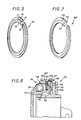
- the assembly means constituted according to the invention by the elastic washer 20, has at rest, as illustrated in FIG. 5, the shape of a torus interrupted by a slot extending over a small portion of the circumference .
- the diameter at rest of this washer is substantially equal to the diameter D o of the current part of the sleeve. In radial section, it has a profile delimited by two straight flanks 31, 32 placed in two planes perpendicular to the axis and separated from each other by a distance d 'slightly less than the axial distance d between the inner and outer rings of the bearing. , and more precisely between the rim 25 of the ring 15 and the adjacent terminal edge of the rotating ring 16.
- this profile On one of its faces comprising the profile 31 (which is located on the left in the drawings) this profile has the side radially inside a frustoconical face 33 and on the radially outside side a rebate 34. On its other face, there is simply provided on the radially inside side a slight chamfer 35.
- the washer 20 is put in place when the bearing constituting the driving member 11 is mounted in the position illustrated in FIG. 1: it can be seen that it finds its place with a certain radial clearance in the annular groove delimited by the radial rim 25 of the non-rotating ring 15, the end face of the rotating ring 16 and by the deflector 18. In the axial direction the clearance corresponds to the difference d - d ''.
- the attack member thus equipped engages without difficulty on the terminal part of the sleeve since the diameter D o of this part is, as we have seen, substantially equal to the diameter at rest of the washer 20; the chamfer 35 facilitates this engagement. The progression continues effortlessly until the start of ramp 30.
- the washer 20 engages by its frustoconical face 33 on the frustoconical flank 28 of the sleeve which has the effect of releasing the elastic energy accumulated by the expansion of the washer along the ramp 30.
- the washer tending to resume its rest configuration (at the diameter D o ) begins a descent of the frustoconical face 33 along the frustoconical flank 28: in axial direction the right flank 31 of the washer separates from the rotating ring 16, while its opposite right flank 32 will bear against the radial rim 25 of the non-rotating ring 15.
- This change of support takes place almost instantaneously in favor of the gentle play in the axial direction, the movement ending in the final position of FIG.
- the washer 20 bearing on the flank 28 due to its radial elasticity, exerts in the direction of the flange 13 an axial thrust, which is here directed towards the top of the cone defining this frustoconical flank.
- the top of the cone is directed in the direction of the axial thrust.
- the internal diameter D1 that reaches in this final position the washer 20 remains greater than its rest diameter D o by a quantity determined according to the invention so that, taking into account the elastic characteristics of the material constituting the washer, the moment of inertia from this, the axial component of the thrust exerted by means of the frustoconical flank 28 of the sleeve provides the required force for tightening the radial flange 25 against the flange 13 of said sleeve in order to allow the self-centering path that the bearing must be able to perform within the limits of the travel determined by the radial clearance J, while ensuring the maintenance of this self-centering.
- the radial rim 25 of the non-rotating ring 15 and the flange 13 of the sleeve 12 will also be called crowns of bearing.
- Figures 6 and 7 illustrate the application of the invention to a clutch release bearing in which the leading nose is carried by the outer race ring.
- the deflector 118 here has a straight profile determining opposite the radial flange 125 directed towards the outside of the non-rotating ring 115 an annular housing of general shape rectangular for the elastic washer 120, the sectional shape of which is simplified consequently with a frustoconical face 133 situated here on the radially outer side.
- This washer will in fact cooperate in the present case with a support means arranged radially inwards of the operating member on a coaxial return 140 which is connected by a series of fastening tabs to the external periphery of the flange radial 113 of sleeve 112, rim which is shown here doubled with a wear plate 113A.
- the support means here again comprises a frustoconical flank 128 adapted to cooperate with the frustoconical face 133 of the washer 120, a lip 129 and an engagement ramp 130.
- the frustoconical flank 128 departs from the flange 113 at the same time as it moves away from the bottom 127 from which it comes.
- the elastic deformation undergone by the washer 120 is a narrowing of its outside diameter up to the minimum value determined by the lip 129 and that the desired tightening is effected by wedging of relaxation of the frustoconical face 133 along the corresponding tapered flank 128 of the support means.
- the washer 120 bearing on the sidewall 128 due to its radial elasticity, exerts in the direction of the flange 113 an axial thrust, which is here directed opposite the top of the cone defining this sidewall frustoconical. It will also be emphasized that the external periphery of the washer 120 is in the final position at a distance from the bottom of the groove so that the axial thrust is maintained.
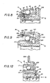
- the stop represented in FIG. 8 differs from the stops described above in that the groove defined by its bottom 27, its support flank 28, its lip 29 and the engagement ramp 30 is formed in the sleeve 12 towards the end of this sleeve axially opposite the flange 13.
- the radial elastic washer 20 thus comes to bear on an end edge 15A of the non-rotating ring 15, axially opposite the flange 25 directed towards the outside of this ring.
- the washer 20 is housed between the end edge 15A of the non-rotating ring 15, and the leading nose 17 of the rotating ring 16.
- the washer 20 carries, engaged in a peripheral groove, a seal 18 '' made of elastomer, with flexible lips which come into contact respectively with the internal face of the leading nose 17 and with the opposite face of the non-rotating ring 15.
- a seal 18 '' made of elastomer, with flexible lips which come into contact respectively with the internal face of the leading nose 17 and with the opposite face of the non-rotating ring 15.
- FIG. 9 represents a stop, where the rim 113 of the sleeve 112 is extended by a coaxial return 140 in analogy with the arrangement of FIG. 6.
- the washer 120 engaged in a groove made in the return 140, with a bottom 127, a frustoconical flank 128, a lip 129 and an engagement ramp 130, comes to take support on a wafer 115A of the non-rotating ring 115, opposite the flange 125 which forms the crown for bearing the non-rotating ring, extending towards the axis, pressing on the abutment crown of the sleeve 112 formed by the rim 113.
- the rotating ring 16 is interior.
- the flange 113 of the sleeve is doubled by an operating or wear plate 113A.
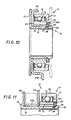
- the stop represented in FIG. 10 presents structural analogies with the stop represented in FIG. 8, in particular in that the elastic washer 20 bears on a edge 15A of the non-rotating ring 15 opposite the bearing crown 25, and in that the rotating ring 16 is external. But this stop is achieved with a very small axial size.
- the bearing 11 includes rings machined in rings.
- the rotating ring 16 has a leading nose 17 along a radial plane, and the non-rotating ring 15 is a ring of rectangular section, so that the bearing ring 25 is a straight edge.
- the stop comprises an operating or wear plate 63, taken between the rim 13 of the sleeve 12 and the bearing ring 25 of the non-rotating ring 15.
- the operating plate 63 comprises ears 63 a , for engagement with the clutch control means.
- the stop shown in Figure 11 has the same structure as that shown in Figure 10.
- the operating plate 63 of Figure 10 is replaced by a crown 65, 66 having a groove of rectangular section open radially outwards.
- This crown consists of a flat cheek 66, bearing on the edge 13 of the sleeve 12, and a cheek 65 integral with a tubular sheath 65 a which comes to rest on the flat cheek 66.
- This plate arrangement maneuver allows positive control of the movement of the stop 10, in traction and in thrust, by the declutching control means (not referenced) which engages in the groove.
- the stop shown in FIG. 12 also has a structure similar to that of FIGS. 10 and 11, with an outer rotating ring 16. But here the non-rotating ring 15 bears against the flange 13 located at the front of the sleeve 12 by an end edge 25 forming a bearing ring, and against an operating plate 63 by its opposite end edge 15A.
- the elastic washer 20 axially clamps the non-rotating ring 15 against the flange 13 by means of the operating plate 63.
- This operating plate 63 has a tubular sheath 63 b threaded on the sleeve 12, and ears 63 a for engaging the clutch control means.
- the groove in which the radial resilient washer 20 engages comprises, as before, a bottom 27, a frustoconical flank 28 remote from the flange 13 of the sleeve, a lip 29 and an engagement ramp 30 in a truncated cone to acute apex angle.
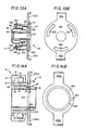
- FIGS. 13A and 13B represent a stop which has analogies with the stop of FIG. 9, with an inner rotating ring 116, and an elastic washer housing groove 120 formed in a return 140 from the rim 113 of the sleeve 112. But this stop comprises an operating plate 63 which is clamped between the rim 113 of the sleeve 112, and the end edge 125 forming a bearing ring for the non-rotating ring 115.
- the return 140 is divided into three tube segments which extend angularly over approximately 60 ° each, and also spaced about 60 ° apart.
- the drive plate 63 is generally disc-shaped, with ears 63 has thrust by the clutch control means.
- the maneuvering plate 63 has a central circular recess for the passage of the sleeve 112, and three recesses 63 c in the form of crown segments, extending over substantially 60 ° and spaced apart substantially 60 °, and provided to allow the return tube segments 140 to pass, including the lip 129 of the retaining groove of the elastic washer 120.
- FIGS. 14A and 14B show a simplified stop. Its structure is analogous to the stop of FIG. 12.
- the washer with radial elasticity 220 is arranged to form an operating plate. It has the shape of a ring, with a slot 221 intended to provide the necessary radial elasticity, and a frustoconical face 223, which comes to bear on the side 28 of the groove of the sleeve 12, to bring the clamping on the edge 15A of the non-rotating ring 15, supported by its other end edge 25 forming a bearing ring against the rim 13 of the sleeve 12.
- the washer 220 comprises, at 90 ° from the slot 221, ears 220 is engaged with the clutch control means.
- the stop consists of only three members, a bearing 11, a sleeve 12 and an operating plate 220.
- FIG. 15 represents a stop of the type called “pulled stop”, while the stops previously described were of the type called “pushed stop”.
- the references relating to the parts corresponding to an element of the stops according to FIG. 1 will be increased by 300 compared to those of this FIG. 1.
- pulled stop is meant a stop which works in traction and whose leading nose 317 is on the side opposite to that of the maneuvering plate 363 relative to the diaphragm the clutch 380.
- the stop comprises a sleeve 312 and a bearing 311 comprising a rotating ring 316 and, a non-rotating ring 315 and between the rings of the balls 314 (as mentioned above) the rotating ring 316 has a attack nose 317 machined in the rear face of a rim.
- the non-rotating ring 315 here interior, carries by its front edge 325 on a flange 313 forming crown rings.
- the edge 325 is held in abutment on the rim 313 by the thrust of a washer 20 with radial elasticity in tightening on the rear edge 315A of the non-rotating ring 315.
- the washer 20 is similar to the washers described with FIGS.
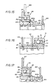
- the stop shown in FIG. 16 is very close to the stop shown in FIG. 11.
- the front edge 25 of the non-rotating ring 15 bears on an anterior flange 13 of the sleeve 12, set back from the leading nose 17 of the rotating ring 16
- On the rear edge 15A of the non-rotating ring 15 comes a cheek 65 secured to a tubular sheath 65 a which constitutes, with a flat cheek 170, an operating crown in which a disengaging control member engages, such as the fingers of a clutch release fork, for positive control of the stopper in both directions.
- the flat cheek 170 has a washer shape with radial elasticity. It is housed as a clamping support in a groove made in the sleeve 12 towards its rear end, and which comprises a bottom 27, a frustoconical flank 28, a lip 29 and an engagement ramp 30.
- the washer 170 does not, as according to the other figures, have a frustoconical face complementary to the support flank 28, and the internal bore of this washer 170 is cylindrical. The edges between the internal bore and the faces of the washer can be simply knocked down to avoid encrustation in the support flank 28.
- the stop shown in Figure 17 is a "pulled stop" similar to that of Figure 15, and has the same references.
- the nose 317 instead of being machined in the rotating ring 16 of the bearing, belongs to a stamped case crimped on this rotating ring.
- the operating member is a crown, consisting of an operating plate 316 and the elastic washer 20.
- the means of declutching control therefore acts in traction on the plate 316, and in thrust on the washer 20.
- the mounting of the stop comprises the positioning of the bearing 311 on the sleeve 312, the insertion of the washer 20 which goes up on the ramp engagement 330, passes over the cylindrical lip 329, to descend along the support flank 328 and tighten the non-rotating ring 315 on the flange 313.
- maneuvering plate 363 is threaded, with the cylindrical sleeve 363A on the shoulder of the sleeve provided for this purpose, and the sleeve 312 is then flared at the rear of the maneuvering plate 363, to crimp the latter.
- the external bore of the sleeve 363A comes flush with the external diameter of the sleeve 312, behind the engagement ramp 330.
- the tightening member with radial elasticity can be made of metal or plastic, and be made up in the most diverse forms; it is thus possible, instead of giving a ring a suitable elastic deformation capacity by a slot, constitute a ring with thinned periphery elements of appropriate shape between at least two cheeks distributed symmetrically around the axis where the support on the support flank 28 or 128 is preserved.
- the support of the bearing crowns of the non-rotating ring (15, 115) can be direct or indirect (as in FIGS. 10, 11 and 13A), and that the support of the elastic washer (20, 120) on this non-rotating ring can be direct, or indirect (as in Figures 12 and 16).
- the contact between the washer and the supporting flank takes place along the frustoconical face which at least one of these members has.
- the choice of the inclination of this face corresponding to the half angle at the top of the cone which defines the frustoconical face, determines the ratio of the axial thrust to the radial elastic return of the washer.
- the tightening of the device in the axial direction remains ensured by the residual elastic energy of the washer, which of course must not bear on the bottom of the groove. Furthermore, the axial size of the elastic washer, taking into account the axial clearances necessary for mounting, is reduced compared to the corresponding size of the axial elasticity washers.
Landscapes
- Engineering & Computer Science (AREA)
- General Engineering & Computer Science (AREA)
- Mechanical Engineering (AREA)
- Mechanical Operated Clutches (AREA)
Applications Claiming Priority (2)
| Application Number | Priority Date | Filing Date | Title |
|---|---|---|---|
| FR8510854 | 1985-07-15 | ||
| FR8510854A FR2584788B1 (fr) | 1985-07-15 | 1985-07-15 | Butee de debrayage a autocentrage maintenu, avec une rondelle de serrage a elasticite radiale |
Publications (1)
| Publication Number | Publication Date |
|---|---|
| EP0211697A1 true EP0211697A1 (de) | 1987-02-25 |
Family
ID=9321329
Family Applications (1)
| Application Number | Title | Priority Date | Filing Date |
|---|---|---|---|
| EP86400181A Withdrawn EP0211697A1 (de) | 1985-07-15 | 1986-01-29 | Selbstzentrierendes Ausrücklager mit einem radial elastischen Sprengring für eine Kupplung |
Country Status (2)
| Country | Link |
|---|---|
| EP (1) | EP0211697A1 (de) |
| FR (1) | FR2584788B1 (de) |
Cited By (3)
| Publication number | Priority date | Publication date | Assignee | Title |
|---|---|---|---|---|
| FR2631402A1 (fr) * | 1988-05-13 | 1989-11-17 | Roulements Soc Nouvelle | Montage d'un palier de roulement sur un porte-fusee de roue de vehicule |
| DE4440132A1 (de) * | 1994-11-10 | 1996-05-15 | Schaeffler Waelzlager Kg | Ausrücklager für eine Reibungskupplung |
| WO1997009542A1 (en) * | 1995-09-01 | 1997-03-13 | Federal-Mogul Corporation | Sealing assembly for clutch release bearing |
Families Citing this family (3)
| Publication number | Priority date | Publication date | Assignee | Title |
|---|---|---|---|---|
| FR2619880B1 (fr) * | 1987-08-24 | 1989-12-01 | Valeo | Butee de debrayage, notamment pour vehicules automobiles |
| FR2936032B1 (fr) * | 2008-09-16 | 2011-08-26 | Skf Ab | Roulement, son utilisation et vehicule automobile equipe d'un tel roulement. |
| DE102009032088A1 (de) * | 2009-07-07 | 2011-01-13 | Maxon Motor Ag | Elektromotor mit Anbaugehäuse |
Citations (10)
| Publication number | Priority date | Publication date | Assignee | Title |
|---|---|---|---|---|
| GB385039A (en) * | 1931-09-23 | 1932-12-22 | George Enoch Stanley | Clutch withdrawal collars |
| FR2125871A5 (de) * | 1971-02-18 | 1972-09-29 | Schaeffler Ohg Industriewerk | |
| EP0030165A1 (de) * | 1979-12-04 | 1981-06-10 | Societe Nouvelle De Roulements S.A. | Selbstzentrierendes Kupplungsausrücklager |
| GB2073353A (en) * | 1980-04-08 | 1981-10-14 | Valeo | Clutch release bearing assembly |
| FR2503297A1 (fr) * | 1981-04-07 | 1982-10-08 | Valeo | Butee de debrayage, notamment pour vehicules automobiles |
| EP0062535A1 (de) * | 1981-04-06 | 1982-10-13 | Skf (U.K.) Limited | Selbstzentrierende Kupplungsausrückvorrichtung |
| EP0080263A1 (de) * | 1981-11-13 | 1983-06-01 | Automotive Products Public Limited Company | Kupplungsausrücklagervorrichtung |
| DE3151473A1 (de) * | 1981-12-24 | 1983-07-07 | INA Wälzlager Schaeffler KG, 8522 Herzogenaurach | Kupplungsausruecklager fuer kraftfahrzeuge |
| FR2526107A1 (fr) * | 1982-05-01 | 1983-11-04 | Nippon Seiko Kk | Dispositif de roulement pour butee d'embrayage |
| US4482041A (en) * | 1981-12-14 | 1984-11-13 | Federal-Mogul Corporation | Self-aligning clutch release bearing assembly with lubrication reservoir |
-
1985
- 1985-07-15 FR FR8510854A patent/FR2584788B1/fr not_active Expired - Lifetime
-
1986
- 1986-01-29 EP EP86400181A patent/EP0211697A1/de not_active Withdrawn
Patent Citations (10)
| Publication number | Priority date | Publication date | Assignee | Title |
|---|---|---|---|---|
| GB385039A (en) * | 1931-09-23 | 1932-12-22 | George Enoch Stanley | Clutch withdrawal collars |
| FR2125871A5 (de) * | 1971-02-18 | 1972-09-29 | Schaeffler Ohg Industriewerk | |
| EP0030165A1 (de) * | 1979-12-04 | 1981-06-10 | Societe Nouvelle De Roulements S.A. | Selbstzentrierendes Kupplungsausrücklager |
| GB2073353A (en) * | 1980-04-08 | 1981-10-14 | Valeo | Clutch release bearing assembly |
| EP0062535A1 (de) * | 1981-04-06 | 1982-10-13 | Skf (U.K.) Limited | Selbstzentrierende Kupplungsausrückvorrichtung |
| FR2503297A1 (fr) * | 1981-04-07 | 1982-10-08 | Valeo | Butee de debrayage, notamment pour vehicules automobiles |
| EP0080263A1 (de) * | 1981-11-13 | 1983-06-01 | Automotive Products Public Limited Company | Kupplungsausrücklagervorrichtung |
| US4482041A (en) * | 1981-12-14 | 1984-11-13 | Federal-Mogul Corporation | Self-aligning clutch release bearing assembly with lubrication reservoir |
| DE3151473A1 (de) * | 1981-12-24 | 1983-07-07 | INA Wälzlager Schaeffler KG, 8522 Herzogenaurach | Kupplungsausruecklager fuer kraftfahrzeuge |
| FR2526107A1 (fr) * | 1982-05-01 | 1983-11-04 | Nippon Seiko Kk | Dispositif de roulement pour butee d'embrayage |
Cited By (3)
| Publication number | Priority date | Publication date | Assignee | Title |
|---|---|---|---|---|
| FR2631402A1 (fr) * | 1988-05-13 | 1989-11-17 | Roulements Soc Nouvelle | Montage d'un palier de roulement sur un porte-fusee de roue de vehicule |
| DE4440132A1 (de) * | 1994-11-10 | 1996-05-15 | Schaeffler Waelzlager Kg | Ausrücklager für eine Reibungskupplung |
| WO1997009542A1 (en) * | 1995-09-01 | 1997-03-13 | Federal-Mogul Corporation | Sealing assembly for clutch release bearing |
Also Published As
| Publication number | Publication date |
|---|---|
| FR2584788B1 (fr) | 1990-03-30 |
| FR2584788A1 (fr) | 1987-01-16 |
Similar Documents
| Publication | Publication Date | Title |
|---|---|---|
| EP0478427B1 (de) | Kupplungssteuereinrichtung, insbesondere für Kraftfahrzeuge | |
| FR2508125A1 (fr) | Butee de debrayage, notamment pour vehicule automobile, et son procede de montage | |
| FR2619880A1 (fr) | Butee de debrayage, notamment pour vehicules automobiles | |
| EP1080317B1 (de) | Sich mittels hülse selbstzentrierendes kupplungsausrücklager | |
| EP0224393B1 (de) | Trennbarer Zusammenbau eines ein Entriegelungselement tragenden Kupplungsausrücklagers, insbesondere für Kraftfahrzeuge | |
| EP0220982B1 (de) | Aufstellung eines Kupplungsausrückers, insbesondere für ein Kraftfahrzeug | |
| FR2756892A1 (fr) | Embrayage a friction a faible effort de debrayage | |
| EP0223645B1 (de) | Trennbarer Zusammenbau eines Kupplungsausrücklagers, insbesondere für Kraftfahrzeuge | |
| EP0192081A1 (de) | Zugkraftbetätigtes Kupplungslager | |
| EP0211697A1 (de) | Selbstzentrierendes Ausrücklager mit einem radial elastischen Sprengring für eine Kupplung | |
| FR2607885A1 (fr) | Butee de debrayage a rondelle elastique bistable, notamment pour vehicule automobile | |
| FR2756602A1 (fr) | Dispositif debrayeur | |
| FR2459906A1 (fr) | Butee d'embrayage a auto-centrage | |
| FR2465120A1 (fr) | Butee de debrayage | |
| FR2579703A1 (fr) | Butee de debrayage, notamment pour vehicule automobile | |
| FR2791746A1 (fr) | Embrayage a friction a dispositif de rattrapage d'usure des garnitures de friction, en particulier pour vehicule automobile | |
| FR2503297A1 (fr) | Butee de debrayage, notamment pour vehicules automobiles | |
| EP0916032B1 (de) | Reibungskupplung mit nachstellvorrichtung | |
| FR2652623A1 (fr) | Dispositif de butee d'embrayage a autocentrage du type tiree. | |
| EP0836685B1 (de) | Befestigung eines kupplungsrücklagers | |
| FR2733808A1 (fr) | Embrayage a friction a rattrapage d'usure | |
| EP0198747A1 (de) | Verfahren zur Herstellung einer Kupplungsvorrichtung und entsprechende Kupplungsvorrichtung | |
| FR2533281A2 (fr) | Butee de debrayage, notamment pour vehicule automobile et son procede de montage | |
| EP0421851B1 (de) | Zugkraftbetätigtes Kupplungslager | |
| FR2553846A1 (fr) | Butee de debrayage, notamment pour vehicule automobile, et son procede de montage |
Legal Events
| Date | Code | Title | Description |
|---|---|---|---|
| PUAI | Public reference made under article 153(3) epc to a published international application that has entered the european phase |
Free format text: ORIGINAL CODE: 0009012 |
|
| AK | Designated contracting states |
Kind code of ref document: A1 Designated state(s): DE FR GB IT |
|
| 17P | Request for examination filed |
Effective date: 19870116 |
|
| 17Q | First examination report despatched |
Effective date: 19880610 |
|
| STAA | Information on the status of an ep patent application or granted ep patent |
Free format text: STATUS: THE APPLICATION IS DEEMED TO BE WITHDRAWN |
|
| 18D | Application deemed to be withdrawn |
Effective date: 19890801 |
|
| RIN1 | Information on inventor provided before grant (corrected) |
Inventor name: GAY, CHRISTIAN Inventor name: LASSIAZ, PHILIPPE |