EP0211699B1 - Brenner mit Wärmerohren zur Luft- und Brennstoffvorheizung - Google Patents
Brenner mit Wärmerohren zur Luft- und Brennstoffvorheizung Download PDFInfo
- Publication number
- EP0211699B1 EP0211699B1 EP86401186A EP86401186A EP0211699B1 EP 0211699 B1 EP0211699 B1 EP 0211699B1 EP 86401186 A EP86401186 A EP 86401186A EP 86401186 A EP86401186 A EP 86401186A EP 0211699 B1 EP0211699 B1 EP 0211699B1
- Authority
- EP
- European Patent Office
- Prior art keywords
- heat pipes
- burner
- smoke gases
- air
- combustion air
- Prior art date
- Legal status (The legal status is an assumption and is not a legal conclusion. Google has not performed a legal analysis and makes no representation as to the accuracy of the status listed.)
- Expired - Lifetime
Links
- 239000000446 fuel Substances 0.000 title claims abstract description 13
- 238000002485 combustion reaction Methods 0.000 claims abstract description 27
- 239000007789 gas Substances 0.000 claims abstract description 15
- 239000000779 smoke Substances 0.000 claims abstract description 12
- 239000012530 fluid Substances 0.000 claims abstract description 5
- 238000010438 heat treatment Methods 0.000 claims abstract description 3
- 239000012895 dilution Substances 0.000 claims description 6
- 238000010790 dilution Methods 0.000 claims description 6
- 239000000567 combustion gas Substances 0.000 description 11
- 239000003517 fume Substances 0.000 description 7
- 210000003462 vein Anatomy 0.000 description 4
- 239000003546 flue gas Substances 0.000 description 3
- 230000005855 radiation Effects 0.000 description 3
- 239000007788 liquid Substances 0.000 description 2
- 238000000034 method Methods 0.000 description 2
- 239000000243 solution Substances 0.000 description 2
- UGFAIRIUMAVXCW-UHFFFAOYSA-N Carbon monoxide Chemical compound [O+]#[C-] UGFAIRIUMAVXCW-UHFFFAOYSA-N 0.000 description 1
- 229910000831 Steel Inorganic materials 0.000 description 1
- 238000000137 annealing Methods 0.000 description 1
- QVGXLLKOCUKJST-UHFFFAOYSA-N atomic oxygen Chemical compound [O] QVGXLLKOCUKJST-UHFFFAOYSA-N 0.000 description 1
- 239000004568 cement Substances 0.000 description 1
- 239000000919 ceramic Substances 0.000 description 1
- 238000004320 controlled atmosphere Methods 0.000 description 1
- 125000004122 cyclic group Chemical group 0.000 description 1
- 230000000694 effects Effects 0.000 description 1
- 230000004907 flux Effects 0.000 description 1
- 239000002737 fuel gas Substances 0.000 description 1
- 238000009434 installation Methods 0.000 description 1
- 238000002844 melting Methods 0.000 description 1
- 230000008018 melting Effects 0.000 description 1
- 239000002184 metal Substances 0.000 description 1
- 239000000203 mixture Substances 0.000 description 1
- 239000007800 oxidant agent Substances 0.000 description 1
- 239000001301 oxygen Substances 0.000 description 1
- 229910052760 oxygen Inorganic materials 0.000 description 1
- 238000006213 oxygenation reaction Methods 0.000 description 1
- 238000011084 recovery Methods 0.000 description 1
- 238000003303 reheating Methods 0.000 description 1
- 239000007787 solid Substances 0.000 description 1
- 239000010959 steel Substances 0.000 description 1
Images

Classifications
-
- F—MECHANICAL ENGINEERING; LIGHTING; HEATING; WEAPONS; BLASTING
- F23—COMBUSTION APPARATUS; COMBUSTION PROCESSES
- F23D—BURNERS
- F23D14/00—Burners for combustion of a gas, e.g. of a gas stored under pressure as a liquid
- F23D14/32—Burners for combustion of a gas, e.g. of a gas stored under pressure as a liquid using a mixture of gaseous fuel and pure oxygen or oxygen-enriched air
-
- F—MECHANICAL ENGINEERING; LIGHTING; HEATING; WEAPONS; BLASTING
- F23—COMBUSTION APPARATUS; COMBUSTION PROCESSES
- F23L—SUPPLYING AIR OR NON-COMBUSTIBLE LIQUIDS OR GASES TO COMBUSTION APPARATUS IN GENERAL ; VALVES OR DAMPERS SPECIALLY ADAPTED FOR CONTROLLING AIR SUPPLY OR DRAUGHT IN COMBUSTION APPARATUS; INDUCING DRAUGHT IN COMBUSTION APPARATUS; TOPS FOR CHIMNEYS OR VENTILATING SHAFTS; TERMINALS FOR FLUES
- F23L15/00—Heating of air supplied for combustion
- F23L15/04—Arrangements of recuperators
-
- Y—GENERAL TAGGING OF NEW TECHNOLOGICAL DEVELOPMENTS; GENERAL TAGGING OF CROSS-SECTIONAL TECHNOLOGIES SPANNING OVER SEVERAL SECTIONS OF THE IPC; TECHNICAL SUBJECTS COVERED BY FORMER USPC CROSS-REFERENCE ART COLLECTIONS [XRACs] AND DIGESTS
- Y02—TECHNOLOGIES OR APPLICATIONS FOR MITIGATION OR ADAPTATION AGAINST CLIMATE CHANGE
- Y02E—REDUCTION OF GREENHOUSE GAS [GHG] EMISSIONS, RELATED TO ENERGY GENERATION, TRANSMISSION OR DISTRIBUTION
- Y02E20/00—Combustion technologies with mitigation potential
- Y02E20/34—Indirect CO2mitigation, i.e. by acting on non CO2directly related matters of the process, e.g. pre-heating or heat recovery
Definitions
- This invention relates to a self-recovering burner.
- burners powered by various fuels are used: solid, liquid or gaseous, having a higher or lower calorific value.
- the oxidizer is atmospheric air, generally pressurized, and possibly enriched with oxygen.
- the fumes are more or less completely exhausted by a real or fictitious counter-current, in the case of regenerators (boilers, cement kilns, cowpers).
- the burner It is also common for the burner to heat an enclosure from which the products of combustion escape at high temperature. This is typical of many reheating and melting furnaces (pits, pottery furnaces, tunnel ovens, pocket heaters, etc.).
- self-recovering burners comprise an outer annular stream, concentric with the burner, through which the combustion gases pass before their evacuation to the atmosphere.
- self-recovering burners including means of thermal conduction between the combustion gases and the combustion air are found in US-A-3163 202 and EP-A-0 039 762.
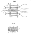
- the burner positioned through the wall of the oven 2, this burner being supplied with fuel, for example gaseous, by a pipe 3, and with combustion air by a pipe 4.
- the burner comprises an external annular vein 5, concentric with the burner, in which the combustion gases circulate, the circulation being obtained by a flow of reducing air admitted by a pipe 6.
- This known device effectively allows part of the heat contained in the combustion gases to be transmitted to the combustion air; however, the combustion air-combustion gas contact surface is small, and the efficiency remains moderate, although we work with very hot fumes whose radiation is important.
- Another example of a more specific application relates to radiant burners used in continuous annealing ovens with controlled atmosphere.
- the fumes from combustion cannot be released into the oven because they would pollute the atmosphere. They are therefore brought back outside the furnace using a pipe concentric with the supply pipe of the combustion air-fuel gas mixture, which is thus preheated. This increases the combustion temperature, and therefore the radiation of the barrel tube.
- publication EP-A 0 039 762 describes a self-recovering burner comprising means of thermal conduction between the combustion gases and the combustion air produced in the form of fins.
- This invention proposes to improve the self-recovering burners, so as to eliminate the drawbacks of the known solutions described above, by using heat pipes to ensure the transfer of heat between the combustion gases and the combustion air, and the fuel feeding the burner.
- heat pipes 15 are used to ensure the heat exchange between the combustion gases and the lean combustible gas, and heat pipes 15 'to effect the heat transfer between these combustion gases and the combustion air.
- the exchange surface has been substantially increased, and a convective exchange has been carried out in addition to the exchange by radiation. We can thus obtain a very high recovery rate.
Landscapes
- Engineering & Computer Science (AREA)
- Chemical & Material Sciences (AREA)
- Combustion & Propulsion (AREA)
- Mechanical Engineering (AREA)
- General Engineering & Computer Science (AREA)
- Gas Burners (AREA)
- Air Supply (AREA)
- Pre-Mixing And Non-Premixing Gas Burner (AREA)
- Combustion Of Fluid Fuel (AREA)
- Incineration Of Waste (AREA)
- Treating Waste Gases (AREA)
- Gas Separation By Absorption (AREA)
- Heat-Exchange Devices With Radiators And Conduit Assemblies (AREA)
Claims (6)
Priority Applications (1)
| Application Number | Priority Date | Filing Date | Title |
|---|---|---|---|
| AT86401186T ATE55476T1 (de) | 1985-06-10 | 1986-06-03 | Brenner mit waermerohren zur luft- und brennstoffvorheizung. |
Applications Claiming Priority (2)
| Application Number | Priority Date | Filing Date | Title |
|---|---|---|---|
| FR8508750A FR2583144B1 (fr) | 1985-06-10 | 1985-06-10 | Perfectionnements apportes aux bruleurs autorecuperateurs |
| FR8508750 | 1985-06-10 |
Publications (2)
| Publication Number | Publication Date |
|---|---|
| EP0211699A1 EP0211699A1 (de) | 1987-02-25 |
| EP0211699B1 true EP0211699B1 (de) | 1990-08-08 |
Family
ID=9320062
Family Applications (1)
| Application Number | Title | Priority Date | Filing Date |
|---|---|---|---|
| EP86401186A Expired - Lifetime EP0211699B1 (de) | 1985-06-10 | 1986-06-03 | Brenner mit Wärmerohren zur Luft- und Brennstoffvorheizung |
Country Status (7)
| Country | Link |
|---|---|
| EP (1) | EP0211699B1 (de) |
| JP (1) | JPS62720A (de) |
| KR (1) | KR870000549A (de) |
| AT (1) | ATE55476T1 (de) |
| BR (1) | BR8602633A (de) |
| DE (1) | DE3673282D1 (de) |
| FR (1) | FR2583144B1 (de) |
Families Citing this family (5)
| Publication number | Priority date | Publication date | Assignee | Title |
|---|---|---|---|---|
| FR2658279B1 (fr) * | 1990-02-13 | 1992-04-24 | Stein Industrie | Dispositif de rechauffage de deux fractions de gaz en echange de chaleur avec des fumees. |
| US6071116A (en) * | 1997-04-15 | 2000-06-06 | American Air Liquide, Inc. | Heat recovery apparatus and methods of use |
| DE19937305C1 (de) * | 1999-08-10 | 2001-03-01 | Riedhammer Gmbh Co Kg | Rekuperatorbrenner und zugehöriger Ofen |
| DE102010051347A1 (de) | 2010-11-13 | 2012-05-16 | Messer Austria Gmbh | Vorrichtung und Verfahren zum Oxidieren von Brennstoffen |
| DE102013014988A1 (de) * | 2013-09-07 | 2015-03-26 | Messer Austria Gmbh | Brenner |
Family Cites Families (11)
| Publication number | Priority date | Publication date | Assignee | Title |
|---|---|---|---|---|
| FR1210907A (fr) * | 1958-09-10 | 1960-03-11 | Babcock & Wilcox France | Réchauffeur d'air à génération |
| DE1229226B (de) * | 1960-07-19 | 1966-11-24 | Indugas Ges Fuer Ind Gasverwen | Industriebrenner mit rekuperativer Brennmittelvorwaermung |
| NL6814200A (de) * | 1967-10-16 | 1969-04-18 | ||
| FR2129019A5 (de) * | 1971-03-11 | 1972-10-27 | Air Ind | |
| GB1409872A (en) * | 1971-06-10 | 1975-10-15 | Foster Wheeler Brown Boilers | Steam boilers having air heaters |
| DE2406467A1 (de) * | 1974-02-11 | 1975-08-21 | Schneider Kg Ask A | Verfahren und vorrichtung zur waermerueckgewinnung bei feuerungsanlagen |
| FR2420734A1 (fr) * | 1978-03-20 | 1979-10-19 | Foster Wheeler Energy Corp | Appareil de prechauffage d'air utilisant des tuyaux de chaleur sans pieces mobiles |
| US4416325A (en) * | 1980-03-31 | 1983-11-22 | Foster Wheeler Energy Corporation | Heat exchanger |
| DE3017618C2 (de) * | 1980-05-08 | 1985-08-08 | Joachim Dr.-Ing. 7250 Leonberg Wünning | Öl- oder gasbeheizter Brenner für Industrieöfen oder dergleichen |
| DE3217509A1 (de) * | 1982-05-10 | 1983-07-07 | Fritz 4902 Bad Salzuflen Laude | Verbesserte entschwefelung von energieerzeuger |
| DK300584A (da) * | 1983-06-21 | 1984-12-22 | Babcock Hitachi Kk | Varmeveksler |
-
1985
- 1985-06-10 FR FR8508750A patent/FR2583144B1/fr not_active Expired
-
1986
- 1986-06-03 DE DE8686401186T patent/DE3673282D1/de not_active Expired - Lifetime
- 1986-06-03 AT AT86401186T patent/ATE55476T1/de active
- 1986-06-03 EP EP86401186A patent/EP0211699B1/de not_active Expired - Lifetime
- 1986-06-05 BR BR8602633A patent/BR8602633A/pt unknown
- 1986-06-09 KR KR1019860004555A patent/KR870000549A/ko not_active Withdrawn
- 1986-06-10 JP JP61134725A patent/JPS62720A/ja active Pending
Non-Patent Citations (2)
| Title |
|---|
| J.L. Roth, La combustion du gaz de haut fourneau dopé, IRSID, janvier 1985 * |
| P.Dunn et D.A. Reay, Heat pipes, second edition, Pergamon Press * |
Also Published As
| Publication number | Publication date |
|---|---|
| FR2583144B1 (fr) | 1989-05-12 |
| FR2583144A1 (fr) | 1986-12-12 |
| EP0211699A1 (de) | 1987-02-25 |
| BR8602633A (pt) | 1987-02-03 |
| KR870000549A (ko) | 1987-02-19 |
| DE3673282D1 (de) | 1990-09-13 |
| JPS62720A (ja) | 1987-01-06 |
| ATE55476T1 (de) | 1990-08-15 |
Similar Documents
| Publication | Publication Date | Title |
|---|---|---|
| CA2619681C (fr) | Prechauffage du combustible et du comburant d'oxybruleurs a partir d'installations de prechauffage d'air de combustion | |
| EP2148935B1 (de) | Verfahren und vorrichtung zur erwärmung eines metallstreifens, insbesondere zu seiner glühung | |
| JP5955958B2 (ja) | ガラスを溶融させるためのハイブリッド設備および方法 | |
| FR2726070A1 (fr) | Appareil de chauffage de fluide a bruleur de surface et a matrice poreuse | |
| EP0643262B1 (de) | Verbrennungsverfahren | |
| JPS62500010A (ja) | 炎発生方法および装置 | |
| JPH04500265A (ja) | 高発光火炎を発生させる方法および装置 | |
| CN115574595B (zh) | 氨燃烧还原低NOx排放连续加热炉窑及控制方法 | |
| FR2576968A1 (fr) | Procede et dispositif pour l'exploitation d'une centrale electrique | |
| EP3114243B1 (de) | Industrieofen zur erhitzung von produkten wie etwa stahlprodukte | |
| EA016077B1 (ru) | Способ нагрева в печи с использованием топлива со слабой тепловой мощностью и печь, в которой применяется этот способ | |
| EP0211699A1 (de) | Brenner mit Wärmerohren zur Luft- und Brennstoffvorheizung | |
| EP1001237A1 (de) | Beheizungsverfahren eines kontinuierlich arbeitenden Ofens für Stahl Produkte und kontinuierlich arbeitender Ofen | |
| JPH04257655A (ja) | 小型ガス燃焼空気ヒーター | |
| LU84337A1 (fr) | Procede pour alimenter en energie un four de rechauffage de produits metallurgiques | |
| FR2537605A1 (fr) | Procede et dispositif pour le prechauffage des agents de combustion, en particulier pour le chauffage des cowpers de hauts fourneaux | |
| US4385568A (en) | Solid fuel furnace | |
| EP0079264B1 (de) | Verfahren zum Stückigmachen von Eisenerzen auf einem Wanderrost und Vorrichtung zur Durchführung des Verfahrens | |
| JP3044286B2 (ja) | 連続焼鈍炉 | |
| RU2213907C1 (ru) | Способ ступенчатого сжигания топлива в котле с охлаждаемыми камерой сгорания и дымогарными трубами | |
| SU1097881A1 (ru) | Проходна печь скоростного струйного нагрева металла | |
| FR2549589A3 (fr) | Recuperateur de chaleur de fumees, a temperature elevee | |
| SU765217A1 (ru) | Способ отоплени стекловаренной печи пр мого нагрева и устройство дл его осуществлени | |
| SU663739A1 (ru) | Тупикова радиационна труба | |
| RU2024795C1 (ru) | Способ работы котла в режиме жидкого шлакоудаления |
Legal Events
| Date | Code | Title | Description |
|---|---|---|---|
| PUAI | Public reference made under article 153(3) epc to a published international application that has entered the european phase |
Free format text: ORIGINAL CODE: 0009012 |
|
| AK | Designated contracting states |
Kind code of ref document: A1 Designated state(s): AT BE CH DE GB IT LI LU NL SE |
|
| 17P | Request for examination filed |
Effective date: 19870701 |
|
| 17Q | First examination report despatched |
Effective date: 19880421 |
|
| GRAA | (expected) grant |
Free format text: ORIGINAL CODE: 0009210 |
|
| AK | Designated contracting states |
Kind code of ref document: B1 Designated state(s): AT BE CH DE GB IT LI LU NL SE |
|
| PG25 | Lapsed in a contracting state [announced via postgrant information from national office to epo] |
Ref country code: IT Free format text: LAPSE BECAUSE OF FAILURE TO SUBMIT A TRANSLATION OF THE DESCRIPTION OR TO PAY THE FEE WITHIN THE PRE;WARNING: LAPSES OF ITALIAN PATENTS WITH EFFECTIVE DATE BEFORE 2007 MAY HAVE OCCURRED AT ANY TIME BEFORE 2007. THE CORRECT EFFECTIVE DATE MAY BE DIFFERENT FROM THE ONE RECORDED.SCRIBED TIME-LIMIT Effective date: 19900808 Ref country code: NL Effective date: 19900808 Ref country code: AT Effective date: 19900808 Ref country code: SE Free format text: THE PATENT HAS BEEN ANNULLED BY A DECISION OF A NATIONAL AUTHORITY Effective date: 19900808 Ref country code: GB Effective date: 19900808 |
|
| REF | Corresponds to: |
Ref document number: 55476 Country of ref document: AT Date of ref document: 19900815 Kind code of ref document: T |
|
| REF | Corresponds to: |
Ref document number: 3673282 Country of ref document: DE Date of ref document: 19900913 |
|
| NLV1 | Nl: lapsed or annulled due to failure to fulfill the requirements of art. 29p and 29m of the patents act | ||
| GBV | Gb: ep patent (uk) treated as always having been void in accordance with gb section 77(7)/1977 [no translation filed] | ||
| PLBE | No opposition filed within time limit |
Free format text: ORIGINAL CODE: 0009261 |
|
| STAA | Information on the status of an ep patent application or granted ep patent |
Free format text: STATUS: NO OPPOSITION FILED WITHIN TIME LIMIT |
|
| PG25 | Lapsed in a contracting state [announced via postgrant information from national office to epo] |
Ref country code: BE Effective date: 19910630 Ref country code: CH Effective date: 19910630 Ref country code: LU Free format text: LAPSE BECAUSE OF NON-PAYMENT OF DUE FEES Effective date: 19910630 Ref country code: LI Effective date: 19910630 |
|
| 26N | No opposition filed | ||
| BERE | Be: lapsed |
Owner name: SOC. FRANCAISE D'ETUDES D'INSTALLATIONS SIDERURGIQ Effective date: 19910630 |
|
| REG | Reference to a national code |
Ref country code: CH Ref legal event code: PL |
|
| PG25 | Lapsed in a contracting state [announced via postgrant information from national office to epo] |
Ref country code: DE Effective date: 19920401 |