EP0211736B1 - Articulation à rotule sans jeu - Google Patents
Articulation à rotule sans jeu Download PDFInfo
- Publication number
- EP0211736B1 EP0211736B1 EP19860401599 EP86401599A EP0211736B1 EP 0211736 B1 EP0211736 B1 EP 0211736B1 EP 19860401599 EP19860401599 EP 19860401599 EP 86401599 A EP86401599 A EP 86401599A EP 0211736 B1 EP0211736 B1 EP 0211736B1
- Authority
- EP
- European Patent Office
- Prior art keywords
- ball joint
- fixed
- flanges
- parts
- brackets
- Prior art date
- Legal status (The legal status is an assumption and is not a legal conclusion. Google has not performed a legal analysis and makes no representation as to the accuracy of the status listed.)
- Expired
Links
Images
Classifications
-
- F—MECHANICAL ENGINEERING; LIGHTING; HEATING; WEAPONS; BLASTING
- F16—ENGINEERING ELEMENTS AND UNITS; GENERAL MEASURES FOR PRODUCING AND MAINTAINING EFFECTIVE FUNCTIONING OF MACHINES OR INSTALLATIONS; THERMAL INSULATION IN GENERAL
- F16C—SHAFTS; FLEXIBLE SHAFTS; ELEMENTS OR CRANKSHAFT MECHANISMS; ROTARY BODIES OTHER THAN GEARING ELEMENTS; BEARINGS
- F16C11/00—Pivots; Pivotal connections
- F16C11/04—Pivotal connections
- F16C11/06—Ball-joints; Other joints having more than one degree of angular freedom, i.e. universal joints
- F16C11/0619—Ball-joints; Other joints having more than one degree of angular freedom, i.e. universal joints the female part comprising a blind socket receiving the male part
- F16C11/0623—Construction or details of the socket member
Definitions
- the present invention relates to a ball joint intended to connect two parts to each other and comprising on the one hand a male element suitable for being fixed to one of the parts and comprising a projecting spherical portion, and on the other hand a female element suitable for being fixed on the other part and formed of two parts which each have a stamped in the form of a portion of a sphere, the two stamped trapping the spherical portion of the male element (see for example GB-A -607,709). It more particularly relates to a joint of this kind which is free of play and a reduced mounting cost.
- the joint according to the invention is characterized in that the female element is formed of two brackets, the two wings of which form one with the other, before mounting, an angle less than 90 °, one of the wings of each bracket being a fixing wing while the second wing has the pressed in the shape of a portion of a sphere, and in that, after assembly, the fixing wings of the brackets are adjacent and in the extension of one another and that their said second wings are applied to each other and fixed to each other.
- the ball joint according to the invention is particularly usable as a vehicle door hinge, as a bonnet or flap hinge, or as an articulation of seats, gates or opening roofs.
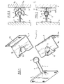
- the ball joint according to the invention comprises a male element 1 and a female element 2.
- the male element 1 is made of molded material, metal or plastic, and comprises a plate or plate 3 which can be fixed for example by screws to a part 4 to be connected to a part 5.
- This plate is integral with a rod 6 which extends substantially perpendicularly to it and is terminated by a spherical portion 7.
- the female element consists of two brackets 8 and 9, one of the wings 8a or 9a is fixed, for example by screwing, to the part 5, the wings 8a and 9a being adjacent and in the extension of one another ( Figure 2).
- the other wing 8b or 9b of each of these brackets makes with the first wing 8a or 9a an angle which is initially less than 90 ° and has in the middle part a stamped trapezoidal shape 10 terminated by a hemispherical portion 11 having substantially the same radius than the spherical portion 7.
- the spherical portion 7 is engaged between the two stampings 11, the two wings 8b and 9b are brought together so as to apply them one on the other, bringing them perpendicular to the wings 8a and 9a, the stampings 11 trapping the spherical portion 7 (FIG. 3), and these wings 8b and 9b are fixed to one another by two welding points, for example using electrodes 12.
Landscapes
- Engineering & Computer Science (AREA)
- General Engineering & Computer Science (AREA)
- Mechanical Engineering (AREA)
- Pivots And Pivotal Connections (AREA)
Description
- La présente invention concerne une articulation à rotule destinée à relier deux pièces l'une à l'autre et comprenant d'une part un élément mâle propre à être fixé à l'une des pièces et comportant en saillie une portion sphérique, et d'autre part un élément femelle propre à être fixé sur l'autre pièce et formé de deux parties qui présentent chacune un embouti en forme de portion de sphère, les deux emboutis emprisonnant la portion sphérique de l'élément mâle (voir par exemple GB-A-607 709). Elle a plus particulièrement pour objet une articulation de ce genre qui est exempte de jeu et d'un coût de montage réduit.
- L'articulation selon l'invention est caractérisée en ce que l'élément femelle est formé de deux équerres dont les deux ailes forment l'une avec l'autre, avant montage, un angle inférieur à 90°, l'une des ailes de chaque équerre étant une aile de fixation alors que la seconde aile présente l'embouti en forme de portion de sphère, et en ce que, après montage, les ailes de fixation des équerres sont adjacentes et dans le prolongement l'une de l'autre et que leurs dites secondes ailes sont appliquées l'une sur l'autre et fixées l'une à l'autre.
- Pour le montage il suffit de fixer l'élément mâle et chacune des équerres sur les pièces à relier, d'introduire la portion sphérique de l'élément mâle entre les emboutis des deux équerres, et enfin d'appliquer l'une sur l'autre des ailes des équerres comportant ces emboutis et de les fixer l'une à l'autre.
- L'articulation à rotule selon l'invention est particulièrement utilisable comme charnière de porte de véhicule, comme charnière de capot ou de volet, ou comme articulation de sièges, de portillons ou de toits ouvrants.
- On a décrit ci-après, à titre d'exemple non limitatif, un mode de réalisation de l'articulation à rotule selon l'invention, avec référence au dessin annexé dans lequel:
- La figure 1 est une vue en perspective montrant séparés les éléments de l'articulation;
- la figure 2 montre en coupe ces éléments fixés sur les pièces à relier, avant leur assemblage;
- la figure 3 est une vue semblable à la figure 2, après assemblage.
- Telle qu'elle est représentée au dessin, l'articulation à rotule selon l'invention comprend un élément mâle 1 et un élément femelle 2.
- L'élément mâle 1 est en matière moulée, métal ou matière plastique, et comprend une plaque ou platine 3 qui peut être fixée par exemple par des vis à une pièce 4 devant être reliée à une pièce 5. Cette plaque fait corps avec une tige 6 qui s'étend sensiblement perpendiculairement à elle et est terminée par une portion sphérique 7.
- L'élément femelle est constitué de deux équerres 8 et 9 dont une des ailes 8a ou 9a est fixée, par exemple par vissage, à la pièce 5, les ailes 8a et 9a étant adjacentes et dans le prolongement l'une de l'autre (Figure 2). L'autre aile 8b ou 9b de chacune de ces équerres fait avec la première aile 8a ou 9a un angle qui est initialement inférieur à 90° et présente dans la partie médiane un embouti de forme trapézoïdale 10 terminé par une portion hémisphérique 11 ayant sensiblement même rayon que la portion sphérique 7.
- Pour monter la rotule, on engage la portion sphérique 7 entre les deux emboutis 11, on rapproche les deux ailes 8b et 9b de façon à les appliquer l'une sur l'autre, en les amenant perpendiculairement aux ailes 8a et 9a, les emboutis 11 emprisonnant la portion sphérique 7 (Figure 3), et on fixe ces ailes 8b et 9b l'une à l'autre par deux points de soudure, par exemple à l'aide d'électrodes 12. On ne sortirait pas du cadre de l'invention en fixant les ailes 8b et 9b par des vis, des boulons ou des rivets.
Claims (3)
Applications Claiming Priority (2)
| Application Number | Priority Date | Filing Date | Title |
|---|---|---|---|
| FR8511271 | 1985-07-18 | ||
| FR8511271A FR2585094B1 (fr) | 1985-07-18 | 1985-07-18 | Articulation a rotule sans jeu |
Publications (2)
| Publication Number | Publication Date |
|---|---|
| EP0211736A1 EP0211736A1 (fr) | 1987-02-25 |
| EP0211736B1 true EP0211736B1 (fr) | 1988-09-14 |
Family
ID=9321567
Family Applications (1)
| Application Number | Title | Priority Date | Filing Date |
|---|---|---|---|
| EP19860401599 Expired EP0211736B1 (fr) | 1985-07-18 | 1986-07-17 | Articulation à rotule sans jeu |
Country Status (3)
| Country | Link |
|---|---|
| EP (1) | EP0211736B1 (fr) |
| DE (1) | DE3660732D1 (fr) |
| FR (1) | FR2585094B1 (fr) |
Families Citing this family (2)
| Publication number | Priority date | Publication date | Assignee | Title |
|---|---|---|---|---|
| FR2641173B1 (fr) * | 1988-12-30 | 1994-03-11 | Cinna Sa | Siege a dossier orientable |
| DE10301532A1 (de) * | 2003-01-17 | 2004-07-29 | Daimlerchrysler Ag | Luftklappe |
Family Cites Families (7)
| Publication number | Priority date | Publication date | Assignee | Title |
|---|---|---|---|---|
| US1554757A (en) * | 1924-09-19 | 1925-09-22 | Clarence E Pope | Bushing and reenforce for rod couplings |
| US2511788A (en) * | 1945-05-18 | 1950-06-13 | Socket assembly | |
| US3299721A (en) * | 1963-12-23 | 1967-01-24 | Gen Motors Corp | Windshield wiper drive and universal joint therefor |
| US3507527A (en) * | 1964-02-12 | 1970-04-21 | Charles S White | Bearing and method of making |
| US3292958A (en) * | 1964-06-10 | 1966-12-20 | Trico Products Corp | Transmission linkage assembly |
| FR2395161A1 (fr) * | 1977-06-20 | 1979-01-19 | Citroen Sa | Perfectionnements apportes aux suspensions de vehicules |
| GB1564539A (en) * | 1977-11-14 | 1980-04-10 | Britax Ltd | Vehicle mirror head and swivel joint assembly |
-
1985
- 1985-07-18 FR FR8511271A patent/FR2585094B1/fr not_active Expired
-
1986
- 1986-07-17 DE DE8686401599T patent/DE3660732D1/de not_active Expired
- 1986-07-17 EP EP19860401599 patent/EP0211736B1/fr not_active Expired
Also Published As
| Publication number | Publication date |
|---|---|
| DE3660732D1 (en) | 1988-10-20 |
| EP0211736A1 (fr) | 1987-02-25 |
| FR2585094B1 (fr) | 1987-11-13 |
| FR2585094A1 (fr) | 1987-01-23 |
Similar Documents
| Publication | Publication Date | Title |
|---|---|---|
| EP0897447B1 (fr) | Charniere a systeme de rappel par anneau elastique | |
| EP0647789B1 (fr) | Boítier de différentiel | |
| EP0908992B1 (fr) | Dispositif de recouvrement variable pour conduit de câblage électrique | |
| EP0211736A1 (fr) | Articulation à rotule sans jeu | |
| FR2791766A1 (fr) | Equipement encliquetable pour un echangeur de chaleur brase, notamment de vehicule automobile | |
| FR2798099A1 (fr) | Siege de vehicule dote d'un mecanisme d'articulation | |
| CA2092436C (fr) | Dispositif de fixation d'au moins deux organes l'un sur l'autre | |
| EP1057552B1 (fr) | Ensemble d'une rotule et d'un triangle de suspension | |
| FR2653081A1 (fr) | Dispositif de connexion a articulation entre deux elements oscillants d'un balai d'essuie-glace. | |
| EP0251844B1 (fr) | Poignée de porte à palette basculante | |
| FR3049016B1 (fr) | Dispositif de fixation d'un soufflet sur un pommeau de levier de commande de boite de vitesses. | |
| EP0299856B1 (fr) | Articulation perfectionnée pour capots de véhicules | |
| FR2622649A1 (fr) | Ensemble de goujon demontable | |
| EP0864763A1 (fr) | Dispositif de fixation amovible destiné notamment à un élément de carrosserie | |
| EP0286497B1 (fr) | Dispositif d'étanchéité de panneau ouvrant de véhicule automobile | |
| EP2764188B1 (fr) | Ensemble de charniere pour l'articulation d'une porte battante de vehicule automobile | |
| EP0511884B1 (fr) | Articulation pour vitre pivotante | |
| EP1932703B1 (fr) | Dispositif d'étanchéité pour l'encadrement d'une ouverture pouvant être fermée par un ouvrant d'un véhicule | |
| FR2729430A1 (fr) | Penture composite dont la constitution facilite le montage | |
| FR2721368A1 (fr) | Joint d'étanchéité. | |
| FR2754008A1 (fr) | Charnieres de portes ajourees pour automobiles et leur procede de fixation | |
| FR2866080A1 (fr) | Systeme de fixation de deux pieces l'une sur l'autre. | |
| FR2882800A1 (fr) | Anneau de liaison articulee pour un ensemble piston-cylindre | |
| FR2692205A1 (fr) | Dispositif d'articulation d'un triangle de suspension ou analogue sur la structure d'un véhicule automobile. | |
| FR2944996A1 (fr) | Train arriere de vehicule a chape support de barre anti devers |
Legal Events
| Date | Code | Title | Description |
|---|---|---|---|
| PUAI | Public reference made under article 153(3) epc to a published international application that has entered the european phase |
Free format text: ORIGINAL CODE: 0009012 |
|
| AK | Designated contracting states |
Kind code of ref document: A1 Designated state(s): DE GB IT |
|
| 17P | Request for examination filed |
Effective date: 19861217 |
|
| 17Q | First examination report despatched |
Effective date: 19871104 |
|
| GRAA | (expected) grant |
Free format text: ORIGINAL CODE: 0009210 |
|
| AK | Designated contracting states |
Kind code of ref document: B1 Designated state(s): DE GB IT |
|
| ITF | It: translation for a ep patent filed | ||
| REF | Corresponds to: |
Ref document number: 3660732 Country of ref document: DE Date of ref document: 19881020 |
|
| ITPR | It: changes in ownership of a european patent |
Owner name: OFFERTA DI LICENZA AL PUBBLICO |
|
| REG | Reference to a national code |
Ref country code: GB Ref legal event code: 746 |
|
| GBT | Gb: translation of ep patent filed (gb section 77(6)(a)/1977) | ||
| PLBE | No opposition filed within time limit |
Free format text: ORIGINAL CODE: 0009261 |
|
| STAA | Information on the status of an ep patent application or granted ep patent |
Free format text: STATUS: NO OPPOSITION FILED WITHIN TIME LIMIT |
|
| 26N | No opposition filed | ||
| PGFP | Annual fee paid to national office [announced via postgrant information from national office to epo] |
Ref country code: GB Payment date: 19920706 Year of fee payment: 7 |
|
| ITTA | It: last paid annual fee | ||
| PGFP | Annual fee paid to national office [announced via postgrant information from national office to epo] |
Ref country code: DE Payment date: 19920928 Year of fee payment: 7 |
|
| PGFP | Annual fee paid to national office [announced via postgrant information from national office to epo] |
Ref country code: GR Payment date: 19921029 Year of fee payment: 7 |
|
| PG25 | Lapsed in a contracting state [announced via postgrant information from national office to epo] |
Ref country code: GB Effective date: 19930717 |
|
| GBPC | Gb: european patent ceased through non-payment of renewal fee |
Effective date: 19930717 |
|
| PG25 | Lapsed in a contracting state [announced via postgrant information from national office to epo] |
Ref country code: DE Effective date: 19940401 |
|
| PG25 | Lapsed in a contracting state [announced via postgrant information from national office to epo] |
Ref country code: IT Free format text: LAPSE BECAUSE OF NON-PAYMENT OF DUE FEES;WARNING: LAPSES OF ITALIAN PATENTS WITH EFFECTIVE DATE BEFORE 2007 MAY HAVE OCCURRED AT ANY TIME BEFORE 2007. THE CORRECT EFFECTIVE DATE MAY BE DIFFERENT FROM THE ONE RECORDED. Effective date: 20050717 |