EP0211795A2 - Récipient en matière plastique repliable - Google Patents
Récipient en matière plastique repliable Download PDFInfo
- Publication number
- EP0211795A2 EP0211795A2 EP86630114A EP86630114A EP0211795A2 EP 0211795 A2 EP0211795 A2 EP 0211795A2 EP 86630114 A EP86630114 A EP 86630114A EP 86630114 A EP86630114 A EP 86630114A EP 0211795 A2 EP0211795 A2 EP 0211795A2
- Authority
- EP
- European Patent Office
- Prior art keywords
- walls
- container
- wall
- hinge
- openings
- Prior art date
- Legal status (The legal status is an assumption and is not a legal conclusion. Google has not performed a legal analysis and makes no representation as to the accuracy of the status listed.)
- Withdrawn
Links
- 239000000463 material Substances 0.000 claims abstract description 9
- 210000002105 tongue Anatomy 0.000 description 13
- 238000010276 construction Methods 0.000 description 7
- 238000005728 strengthening Methods 0.000 description 7
- 230000004048 modification Effects 0.000 description 1
- 238000012986 modification Methods 0.000 description 1
Images


Classifications
-
- B—PERFORMING OPERATIONS; TRANSPORTING
- B65—CONVEYING; PACKING; STORING; HANDLING THIN OR FILAMENTARY MATERIAL
- B65D—CONTAINERS FOR STORAGE OR TRANSPORT OF ARTICLES OR MATERIALS, e.g. BAGS, BARRELS, BOTTLES, BOXES, CANS, CARTONS, CRATES, DRUMS, JARS, TANKS, HOPPERS, FORWARDING CONTAINERS; ACCESSORIES, CLOSURES, OR FITTINGS THEREFOR; PACKAGING ELEMENTS; PACKAGES
- B65D11/00—Containers having bodies formed by interconnecting or uniting two or more rigid, or substantially rigid, components made wholly or mainly of plastics material
- B65D11/18—Containers having bodies formed by interconnecting or uniting two or more rigid, or substantially rigid, components made wholly or mainly of plastics material collapsible, i.e. with walls hinged together or detachably connected
- B65D11/1846—Containers having bodies formed by interconnecting or uniting two or more rigid, or substantially rigid, components made wholly or mainly of plastics material collapsible, i.e. with walls hinged together or detachably connected whereby all side walls are hingedly connected to each other
Definitions
- the present invention relates to a collapsible plastic container, namely to a container which can be conveniently opened for use in holding various types of goods, and also collapsed for storage or transportation.
- An object of the present invention is to provide a collapsible plastic container having advantages in some or all of the above respects.
- the present invention provides a collapsible plastic container comprising a pair of side walls of plastic material formed with a plurality of air-circulation openings therethrough; and a pair of end walls of plastic material formed with a plurality of of air-circulation openings therethrough; and hinges mounting each end wall between a pair of side walls to form a container in which the walls are hinged for movement either to an open condition wherein the walls are disposed perpendicularly to each other to form a container of rectangular configuration, or to a collapsed condition wherein the walls are folded on top of each other for storage or transportation.
- Each of the walls includes internally-extending bottom ledges adapted to receive a bottom wall of plastic material formed with a plurality of air-circulation openings therethrough. The bottom wall is supported on the bottom ledges in the open condition of the container so as to rigidify the container, and is removable from the ledges to permit collapse of the container.
- each of the side and end walls is integrally formed at one end with a laterally-extending retainer tongue, and the end of the contiguous wall is formed with a retainer member having a slot adapted to receive the retainer tongue in the open condition of the container to retain the walls in their open condition until the bottom wall is applied over the bottom ledges.
- each of the retainer tongues includes a cam face yieldingly engaging the side of the slot in its respective retainer member during the movement of the two respective walls to their open condition, and a shoulder which is snapped into engagement behind the edge of the slot in its respective retainer member when the two walls have reached their open condition.
- each of the side and end walls is formed with an upper series of air-circulation openings configured and dimensioned to impart high rigidity to the upper end of the wall; a lower series of air-circulation openings configured and dimensioned to impart less rigidity to the lower end of the wall; and an intermediate series of air-circulation openings configured and dimensioned to impart even less rigidity to the intermediate portion of the wall.
- each of the hinge pins is formed with an enlarged head at one end engageable with one side of the respective hinge socket, the opposite end of each hinge pin being tapered for passing it through the hinge sockets of the contiguous walls, the tapered end of the hinge pin terminating in an annular shoulder engageable with the opposite end of the hinge sockets.
- each of the hinge pins is formed with a slot beginning at a point between the tip of the tapered end of the hinge pin and the annular shoulder thereof, and extending past the annular shoulder, to increase the resiliency of the tapered end of the hinge pin when inserted into the hinge sockets.
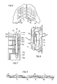
- the container illustrated in the drawings comprises a pair of end walls 2, 4 hingedly mounted to a pair of side walls 6, 8 by a plurality of hinges, each generally designated 10, permitting the walls to be moved to an open condition, as illustrated in Fig. 1 wherein the walls are disposed perpendicularly to each other to form a container of rectangular configuration, or to a collapsed condition, as illustrated in Fig. 9 wherein the walls are folded on top of each other for storage or transportation.
- a bottom wall 12 is inserted within the two end walls 2, 4 and the two side walls 6, 8, and retains the container in its open condition; when the container is to be collapsed to its folded condition as illustrated in Fig. 9, the bottom wall 12 is removed and placed on top of the folded side and end walls.
- All of the walls of the container are made of plastic material and are formed with a plurality of air-circulation openings therethrough.
- the two end walls 2, 4 are of identical construction, best illustrated in Fig. 2 with respect to end wall 4; the two side walls 6, 8 are also of identical construction, best illustrated in Fig. 3 with respect to side wall 6; and the construction of the bottom wall 12 is best illustrated in Fig. 4.
- the two end walls 2, 4, as best seen in Fig. 2, are each integrally formed with an upper horizontal series of air-circulation openings 21 configured and dimensioned to impart high rigidity to the upper end of the wall; a lower horizontal series of air-circulation openings 22 configured and dimensioned to impart less rigidity to the lower end of the wall; and an intermediate horizontal series of openings 23 configured and dimensioned to impart even less rigidity to the intermediate portion of the wall.
- end wall 2 is further formed with a vertical series of openings 24, 25, at its opposite ends configured to impart high rigidity to the opposite ends of the wall.
- End wall is also formed with a plurality of strengthening ribs including a plurality of vertically-extending ribs 26, a plurality of horizontally-extending ribs 27, and a pair of diagonally-extending ribs 28.
- each end wall 2, 4 are each formed with a rectangular opening 29 centrally of its upper end serving as hand-grip openings to enable carrying the container when in its open condition and filled with articles.
- the portion 29' of each end wall 2, 4 underlying the hand-grip openings 29 is left filled with plastic to increase the rigidity thereof when a lifting force is applied.
- each side wall also is formed with: an upper horizontal series of openings 31, configured and dimensioned to impart high rigidity to the upper end of the wall; a lower horizontal series of openings 32 to impart less rigidity to the lower end of the wall; an intermediate horizontal series of openings 33 to impart even less rigidity to the intermediate portion of the wall; a vertical series of openings 34 along one side of the wall providing a high rigidity to that side; a vertical series of openings 35 along the opposite of the wall also providing high rigidity to that side of the wall; a plurality of vertically-extending strengthening ribs 36; a plurality of horizontally-extending strengthening ribs 37; and a pair of diagonally-extending strengthening ribs 38.
- the upper series of openings 21, 31 in the end walls 2, 4 and side walls 6, 8 are of circular configuration;
- the lower series of openings 22, 32 are of rectangular configuration;
- the intermediate series of openings 23, 33 are also of rectangular configuration but have a longer vertical dimension than horizontal dimension;
- the end openings 24, 34 are of circular configuration but of smaller diameter than the upper openings 21, 31;
- the other end openings 25, 35 are of circular configuration of approximately the same diameter as the upper series of openings 21, 31.
- the foregoing construction of the two end walls 2, 4 and the two side walls 6, 8 of the container provides the following characteristics to the container when the container is in its open condition:
- the lower sections of the container walls occupied by the lower series of openings 22, 32 impart less rigidity to the respective walls of the container since the rigidity at the lower part of the container is enhanced by the pressence of the bottom wall 12 when the container is in its open condition.
- the intermediate portions of the container walls occupied by the intermediate openings 23, 33, imparting even less rigidity, provide these sections of the walls with yieldability to minimize the possibility of damage to the goods, such as produce, filling the container.
- a container including the side and end walls of the illustrated construction exhibits a magnitude of strength against top pressure and rotary moments approaching that of solid-wall containers.
- a container provides a surface area which is approximately 50% exposed to air, thereby enabling a high degree of air circulation through the walls, which is very important in plastic containers since plastic does not "breathe".
- the illustrated construction reduces considerably the weight and the cost of the container as compared to solid-wall containers.
- the bottom wall 12 of the container illustrated in Fig. 4 is also formed with a plurality of air-circulation openings 41. But in this case, all the openings 41 are of substantially the same rectangular configuration.
- Bottom wall 12 is further formed with a plurality of strengthening ribs 43, along our axis, a plurality of strengthening ribs 44 along the other orthogonal axis, and a pair of diagonally-extending strengthening ribs 45, 46.
- Each of the hinges 10 is constructed as illustrated in Fig. 7.
- the two contiguous walls at each hinge 10 are integrally formed with a pair of hinge sleeves 50 extending laterally of the respective wall and vertically spaced from each other so as to permit the two hinge sleeves of one wall to interfit and align with the hinge sleeves of the other wall to produce a socket for receiving the hinge pin 52.
- Each of the hinge sleeves 50 is formed with an annular flange 50a, 50b at its opposite ends of larger diameter than its intermediate portion 50c.
- Each hinge pin 52 is formed with an elongated shank 52a received within the aligned hinge sleeves 50, with a pair of enlarged heads 52b, 52c at one end of the pin, and with a tapered end 52d at the opposite end to facilitate passing the pin through the aligned sleeves.
- Tapered end 52d of each hinge pin 52 terminates in an annular shoulder 52e at its juncture with the shank 52a of the pin; this annular shoulder is engageable with the outer surface of the end hinge sleeve 50 when the hinge pin is in place.
- each hinge pin 52 is formed with a slot 52f starting at a point between the tip of the tapered end 52d and the annular shoulder 52e, slot 52f extending past the annular shoulder into the juncture portion with shank 52a.
- slot 52f is to increase the resiliency of the tapered end 52d of the pin to enable the pin to be force-fitted through the aligned sleeves 50 until shoulder 52e of the pin engages the lower surface of the end hinge sleeve; and the purpose of providing the two enlarged heads 52b, 52c at the opposite end of the pin is to permit the pin to be impacted by a hammer or like instrument when forcing the hinge pin through the aligned sleeves 50 at each hinge 10.
- each of the end walls 2, 4 is formed with a plurality of inwardly-extending ledges 60 spaced along the bottom edge of the wall.
- Each of the side walls 6, 8 is found with a plurality of similar ledges 62, but each such ledge is formed with an axial rib 64 (Figs. 4, 4a) having a thickened slot 63 therethrough bordering the wall.
- the bottom wall 12 is in turn formed along each of its two long sides with a downwardly extending rib 64 receivable within slots 63 of the ledges 62 for releasably retaining the bottom wall in place between the end and side walls of the container when the container is in its open condition.
- At least one of the walls 2, 4, 6, 8 is integrally formed at one end with a laterally-extending retainer tongue, and a contiguous wall is integrally formed with a retainer member having a slot adapted to receive the retainer tongue in the open condition of the container.
- the retainer tongue shown at 70 in Fig. 3 is provided at one end of each of the two end walls 2, 4; and the slotted retainer member, shown at 72 in Fig. 3, is provided at the contiguous end of each of the two side walls 6, 8.
- retainer tongue 70 is formed with a cam face 70a which, because of its yielding connection 70b to the end wall (2, 4), yieldingly enagages the edge of the slot 72a in the retainer member 72 integrally formed at the end of each side wall 6, 8.
- cam surface 70a of tongue 70 first engages the edge of slot 72a of retainer member 72 and yields during the continued movement of the walls because of the yielding connection 70b of the tongue, until the walls are brought perpendicularly to each other; at this time shoulder 70c formed at the juncture of tongue 70a and its yieldable connection 70b to its wall, snaps into engagement with the edge of slot 72a.
- the tongues 70 thus retain the four walls 2, 4, 6 and 8 perpendicularly to each other in the open condition of the container until the bottom wall 12 is inserted on top of the ledges 60, 62. When the bottom wall has been so inserted, it firmly retains the four walls in their open condition.
- the illustrated container may be opened for use by merely spreading the end walls 2, 4 and the side walls 6, 8 apart until tongues 70 are snapped into the slots 72a in the retainer members 72 of the contiguous walls.
- the bottom wall 12 may then be placed over the ledges 60, 62 of the side and end walls 2, 4, 6 and 8, and ribs 64, inserted into slots 63 of ledges 62.
- the ledges thereby retain the bottom wall in place even though the empty container is moved or inverted.
- a rigid container structure is thus provided for containing all types of products.
- bottom wall 12 is manually removed, and the remaining four walls 2, 4, 6 and 8 are manually forced towards each other. This is permitted by the yieldability of junctures 70b of tongues 70c with respect to their walls. The walls are then moved to their collapsed condition as illustrated in Fig. 9, thereby providing a compact assembly for storage or transportation.
- each of the two end walls 2, 4 is formed with an upstanding rib 80 extending along the complete length of its upper edge, and with a further rib 82 extending along its lower edge. Rib 82 is formed with a trapezoidal recess 84 midway of the length of the wall.
- each of the two side walls, 6, 8 is similarly formed with a rib 86 extending the complete length of its upper edge, and with a lower rib 88 extending along its lower edge; the lower ribs 88, however, are formed with two trapezoidal recesses 89 spaced at one-third and two-thirds, respectively, of the length of the wall.
- ribs and recesses permit a plurality of like containers to be stacked on top of each other in a plurality of layers with the containers of each layer straddling a pair of containers of the underlying layer, and with the ribs of the underlying layer, received in the recesses of the overlying layer to stabilize the stack.
- FIG. 10 Such a stacking arrangement is illustrated in Fig. 10, wherein it will be seen that containers C1-C3 of the overlying layer are applied over the containers C4-C6 of the underlying layer with the lower recesses 84 of the end walls of the overlying layer straddling the upper ribs 86 in the side walls of two adjacent containers in the underlying layer.
Landscapes
- Engineering & Computer Science (AREA)
- Mechanical Engineering (AREA)
- Rigid Containers With Two Or More Constituent Elements (AREA)
Applications Claiming Priority (2)
| Application Number | Priority Date | Filing Date | Title |
|---|---|---|---|
| IL75934A IL75934A (en) | 1985-07-29 | 1985-07-29 | Collapsible plastic container |
| IL75934 | 1985-07-29 |
Publications (2)
| Publication Number | Publication Date |
|---|---|
| EP0211795A2 true EP0211795A2 (fr) | 1987-02-25 |
| EP0211795A3 EP0211795A3 (fr) | 1987-10-28 |
Family
ID=11056106
Family Applications (1)
| Application Number | Title | Priority Date | Filing Date |
|---|---|---|---|
| EP86630114A Withdrawn EP0211795A3 (fr) | 1985-07-29 | 1986-07-21 | Récipient en matière plastique repliable |
Country Status (5)
| Country | Link |
|---|---|
| US (1) | US4820383A (fr) |
| EP (1) | EP0211795A3 (fr) |
| AU (1) | AU591694B2 (fr) |
| ES (1) | ES2000774A6 (fr) |
| IL (1) | IL75934A (fr) |
Cited By (5)
| Publication number | Priority date | Publication date | Assignee | Title |
|---|---|---|---|---|
| EP0523490A1 (fr) * | 1991-07-19 | 1993-01-20 | Uri Levy | Bac pliant |
| AT401765B (de) * | 1992-11-18 | 1996-11-25 | Furtner Josef | Behälter mit verschwenkbaren seitenwänden |
| WO2006116824A3 (fr) * | 2005-04-22 | 2007-03-15 | Kamran Mahmudov | Caisse polymere |
| WO2016132348A1 (fr) * | 2015-02-16 | 2016-08-25 | Dolav Plastic Products Cooperative Society Ltd. | Bac de stockage pliable très résistant |
| ITUB20153878A1 (it) * | 2015-09-24 | 2017-03-24 | Atelier Archiand Srl | Struttura di vaschetta espositiva con sistema facilitato di montaggio di lastre sovrapposte intercambiabili |
Families Citing this family (35)
| Publication number | Priority date | Publication date | Assignee | Title |
|---|---|---|---|---|
| CA2071776C (fr) * | 1991-06-28 | 2003-02-18 | William E. Wheeler | Contenant a fromage repliable |
| US5230435A (en) * | 1992-11-18 | 1993-07-27 | Mo Yhu Kee | Bendable load carrier |
| IT230329Y1 (it) * | 1993-07-01 | 1999-06-02 | Sviluppo Settori Impiego Srl | Cassetta pieghevole per ortofrutta |
| GB2303616B (en) * | 1995-07-26 | 1999-09-15 | Mckechnie Uk Ltd | Collapsible container |
| DE29701203U1 (de) * | 1997-01-24 | 1998-06-25 | Koordination Globus Betriebe GmbH & Co. KG, 66606 St Wendel | Haushaltskühlbox |
| AU136959S (en) * | 1998-03-13 | 1999-04-06 | Perstorp Plastic Syst Ab | Transport container |
| US7048134B1 (en) * | 2000-07-18 | 2006-05-23 | Rehrig Pacific Company | Container |
| USD458753S1 (en) | 2000-09-21 | 2002-06-18 | Rehrig Pacific Co. | Container |
| USD452614S1 (en) | 2000-10-28 | 2002-01-01 | Rehrig Pacific Company | Collapsible container |
| US6631822B1 (en) * | 2000-10-28 | 2003-10-14 | Rehrig Pacific Company | Collapsible container |
| USD481542S1 (en) | 2001-12-11 | 2003-11-04 | Steco Logistic Gmbh | Carrying container |
| US6752285B1 (en) | 2002-04-08 | 2004-06-22 | Wallace J. Scalf | Storage and shipping bin |
| US8261923B2 (en) * | 2008-04-22 | 2012-09-11 | Otto Industries North America, Inc. | Collapsible container |
| DE102010010049A1 (de) * | 2010-03-03 | 2011-09-08 | Schoeller Arca Systems Gmbh | Großladungsträger |
| EP2431287B1 (fr) | 2010-09-20 | 2013-07-24 | IFCO Systems GmbH | Caisse |
| US9469429B2 (en) * | 2010-09-20 | 2016-10-18 | Ifco Systems Gmbh | Crate |
| US8424710B2 (en) * | 2010-09-20 | 2013-04-23 | Ifco Systems Gmbh | Crate |
| MX2013003052A (es) * | 2010-09-20 | 2013-10-17 | Ifco Systems Gmbh | Cajon con paredes laterales que comprende la entrada para un líquido refrigerante. |
| CA2776643A1 (fr) * | 2011-05-11 | 2012-11-11 | Rehrig Pacific Company | Caisse pliable |
| US10750727B1 (en) | 2013-02-26 | 2020-08-25 | Tyson Foods, Inc. | Portable basket colony for growing and transport and method of use |
| US9737056B2 (en) * | 2013-02-26 | 2017-08-22 | Tyson Foods, Inc. | Portable basket colony for growing and transport and method of use |
| WO2015134067A1 (fr) * | 2014-03-05 | 2015-09-11 | A.R. Arena Products, Inc. | Contenant en plastique réutilisable pour expédition de produits |
| US9550602B2 (en) | 2013-09-18 | 2017-01-24 | Allpillars, Inc. | Collapsible reusable carrying cases |
| CA2960500A1 (fr) | 2016-03-11 | 2017-09-11 | Rehrig Pacific Company | Caisse ecrasable a apparence de bois |
| US12448172B2 (en) | 2018-03-05 | 2025-10-21 | Rehrig Pacific Company | Collapsible container |
| US11597557B2 (en) | 2018-10-04 | 2023-03-07 | Rehrig Pacific Company | Reconfigurable beverage crate |
| US11008134B2 (en) * | 2018-10-26 | 2021-05-18 | Dustin Kyle Nolen | Foldable and/or collapsible plastic/composite utility enclosures |
| US11338524B1 (en) | 2018-10-26 | 2022-05-24 | Afl Telecommunications Llc | Method of forming a foldable or collapsible plastic and/or composite utility enclosure |
| US11066802B1 (en) * | 2019-10-25 | 2021-07-20 | Tan Composites, Llc | Foldable and/or collapsible plastic/composite utility enclosure |
| US11374386B2 (en) * | 2018-10-26 | 2022-06-28 | Afl Telecommunications Llc | Foldable and/or collapsible plastic/composite utility enclosure |
| US11349281B1 (en) | 2018-10-26 | 2022-05-31 | Afl Telecommunications Llc | Foldable and/or collapsible plastic/composite utility enclosure |
| US11447289B1 (en) * | 2018-12-13 | 2022-09-20 | Amazon Technologies, Inc. | Collapsible container |
| CA3172382A1 (fr) | 2021-09-16 | 2023-03-16 | Rehrig Pacific Company | Caisse escamotable hybride |
| US12344435B2 (en) * | 2022-04-28 | 2025-07-01 | Intercrate Container Corp. | Sliding stackable container |
| USD1109532S1 (en) * | 2024-04-11 | 2026-01-20 | Skov A/S | Crate |
Family Cites Families (16)
| Publication number | Priority date | Publication date | Assignee | Title |
|---|---|---|---|---|
| US3119508A (en) * | 1960-03-29 | 1964-01-28 | Reynolds Metals Co | Collapsible container |
| US3254786A (en) * | 1964-04-29 | 1966-06-07 | John B Melville | Folding carrying case |
| US3371816A (en) * | 1965-10-22 | 1968-03-05 | Fausto M. Ricci | Collapsible receptacle |
| AU437558B2 (en) * | 1968-06-03 | 1973-07-02 | Clifford Simkins John | Improvements in and relating to containers |
| DE2160601A1 (de) * | 1970-12-10 | 1972-06-29 | Roddier, Roger, Thiers, Puy de Dome (Frankreich) | Zerlegbare Kisten aus plastischem Material mit leichtvergitterten Öffnungen für das Darbieten und den Transport von leichtverderblichen Waren |
| US3973692A (en) * | 1973-08-23 | 1976-08-10 | Nosco Plastics, Inc. | Injection molded folding box |
| FR2260501A1 (en) * | 1974-02-07 | 1975-09-05 | Mazuir Pierre Jean | Collapsible packaging container - injection moulded in one piece sides fold up and corner uprights interlock |
| US4044910A (en) * | 1976-05-05 | 1977-08-30 | Box Theodor | Collapsible crate |
| SE413491B (sv) * | 1978-09-08 | 1980-06-02 | Sinjet Ab | Pallkrage |
| US4320845A (en) * | 1978-12-07 | 1982-03-23 | Waller John G | Collapsible container |
| AU6387580A (en) * | 1979-10-30 | 1981-05-07 | Castalloy Ltd. | Collapsible bin surround for pallet base |
| GB2068338A (en) * | 1980-01-31 | 1981-08-12 | Larosiere De Champfeu P De | Box for trays or cartons of eggs |
| KR830002832Y1 (ko) * | 1982-03-11 | 1983-12-10 | 동화엔지니어링주식회사 | 절첩식 과일상자 |
| US4508237A (en) * | 1982-04-09 | 1985-04-02 | Pinckney Molded Plastics, Inc. | Collapsible container |
| US4491231A (en) * | 1983-05-13 | 1985-01-01 | Family Distributors, Inc. | Collapsible case |
| AU594798B2 (en) * | 1987-07-28 | 1990-03-15 | Ko-Lin Sun | A collapsible plastic crate |
-
1985
- 1985-07-29 IL IL75934A patent/IL75934A/xx not_active IP Right Cessation
-
1986
- 1986-06-30 US US06/879,961 patent/US4820383A/en not_active Expired - Lifetime
- 1986-07-21 EP EP86630114A patent/EP0211795A3/fr not_active Withdrawn
- 1986-07-28 ES ES8600648A patent/ES2000774A6/es not_active Expired
- 1986-08-20 AU AU61617/86A patent/AU591694B2/en not_active Ceased
Cited By (10)
| Publication number | Priority date | Publication date | Assignee | Title |
|---|---|---|---|---|
| EP0523490A1 (fr) * | 1991-07-19 | 1993-01-20 | Uri Levy | Bac pliant |
| AT401765B (de) * | 1992-11-18 | 1996-11-25 | Furtner Josef | Behälter mit verschwenkbaren seitenwänden |
| US5588549A (en) * | 1992-11-18 | 1996-12-31 | Steiner Freizeitmobel Gesellschaft M.B.H. & Co. Kg. | Container with swivelling sidewalls |
| EP0773171A2 (fr) | 1992-11-18 | 1997-05-14 | STEINER FREIZEITMÖBEL GESELLSCHAFT M.B.H. & Co. KG. | Récipient à parois latérales pivotantes |
| WO2006116824A3 (fr) * | 2005-04-22 | 2007-03-15 | Kamran Mahmudov | Caisse polymere |
| MD3778G2 (ro) * | 2005-04-22 | 2009-07-31 | Камран МАХМУДОВ | Ladă de polimer |
| CN101263060B (zh) * | 2005-04-22 | 2011-06-22 | 卡姆朗·马赫穆多夫 | 聚合物箱 |
| WO2016132348A1 (fr) * | 2015-02-16 | 2016-08-25 | Dolav Plastic Products Cooperative Society Ltd. | Bac de stockage pliable très résistant |
| ITUB20153878A1 (it) * | 2015-09-24 | 2017-03-24 | Atelier Archiand Srl | Struttura di vaschetta espositiva con sistema facilitato di montaggio di lastre sovrapposte intercambiabili |
| EP3146870A1 (fr) * | 2015-09-24 | 2017-03-29 | Atelier Archiand S.r.l. | Construction de bassin d'exposition possédant un système d'assemblage simplifié permettant de monter des plaques superposées interchangeables |
Also Published As
| Publication number | Publication date |
|---|---|
| AU6161786A (en) | 1988-02-25 |
| IL75934A0 (en) | 1985-12-31 |
| US4820383A (en) | 1989-04-11 |
| IL75934A (en) | 1990-01-18 |
| ES2000774A6 (es) | 1988-03-16 |
| EP0211795A3 (fr) | 1987-10-28 |
| AU591694B2 (en) | 1989-12-14 |
Similar Documents
| Publication | Publication Date | Title |
|---|---|---|
| US4820383A (en) | Collapsible plastic container | |
| US5671857A (en) | Collapsible container | |
| US4722440A (en) | Tray for transporting internal combustion engine pistons | |
| US4687129A (en) | Reusable container | |
| EP0931727B1 (fr) | Récipient empilable | |
| US4823955A (en) | Nesting and stacking storage container | |
| US6036049A (en) | Reusable produce crate | |
| US6708836B2 (en) | Container consisting of a plurality of plates | |
| US5299700A (en) | Container with composite structure | |
| CA2086274C (fr) | Emballage en carton pour aliments | |
| US4739921A (en) | Storage box with tray | |
| US8720736B2 (en) | Storage box | |
| EP0373547B1 (fr) | Caisse d'envoi pour l'emballage d'unités | |
| US2675264A (en) | Bottle carrier | |
| US2335914A (en) | Cup package and carton therefor | |
| US2777597A (en) | Stackable tote box construction | |
| CA2136554C (fr) | Conteneur demontable | |
| US4236664A (en) | Stackable transport container | |
| US20240278979A1 (en) | Bulk bin, bulk bin sleeve pack, and related method | |
| US7837037B2 (en) | Two stacking position square container | |
| EP0785135A1 (fr) | Casier à bouteilles en deux parties | |
| US3790061A (en) | Reusable container | |
| GB2160850A (en) | Stackable receptacle | |
| GB2306944A (en) | A stackable or nestable container | |
| JP3287378B2 (ja) | 運搬用矩形容器 |
Legal Events
| Date | Code | Title | Description |
|---|---|---|---|
| PUAI | Public reference made under article 153(3) epc to a published international application that has entered the european phase |
Free format text: ORIGINAL CODE: 0009012 |
|
| AK | Designated contracting states |
Kind code of ref document: A2 Designated state(s): AT BE CH DE FR GB IT LI NL SE |
|
| PUAL | Search report despatched |
Free format text: ORIGINAL CODE: 0009013 |
|
| AK | Designated contracting states |
Kind code of ref document: A3 Designated state(s): AT BE CH DE FR GB IT LI NL SE |
|
| STAA | Information on the status of an ep patent application or granted ep patent |
Free format text: STATUS: THE APPLICATION IS DEEMED TO BE WITHDRAWN |
|
| 18D | Application deemed to be withdrawn |
Effective date: 19880429 |
|
| RIN1 | Information on inventor provided before grant (corrected) |
Inventor name: SHCHAMOROV, SHLOMO Inventor name: SCHNAPP, AHARON |