EP0211809A2 - Structure réglable en longueur au moyen d'un dispositif hydraulique à circuit fermé interne, notamment une structure de colonne verticale d'un support de siège d'une chaise - Google Patents
Structure réglable en longueur au moyen d'un dispositif hydraulique à circuit fermé interne, notamment une structure de colonne verticale d'un support de siège d'une chaise Download PDFInfo
- Publication number
- EP0211809A2 EP0211809A2 EP86830151A EP86830151A EP0211809A2 EP 0211809 A2 EP0211809 A2 EP 0211809A2 EP 86830151 A EP86830151 A EP 86830151A EP 86830151 A EP86830151 A EP 86830151A EP 0211809 A2 EP0211809 A2 EP 0211809A2
- Authority
- EP
- European Patent Office
- Prior art keywords
- extension
- cylinder
- telescopic
- unit
- box
- Prior art date
- Legal status (The legal status is an assumption and is not a legal conclusion. Google has not performed a legal analysis and makes no representation as to the accuracy of the status listed.)
- Withdrawn
Links
- 239000007788 liquid Substances 0.000 claims description 4
- 230000000694 effects Effects 0.000 claims description 2
- 230000006835 compression Effects 0.000 abstract 1
- 238000007906 compression Methods 0.000 abstract 1
- 238000010276 construction Methods 0.000 description 3
- 239000000463 material Substances 0.000 description 3
- 229910000831 Steel Inorganic materials 0.000 description 2
- 239000010959 steel Substances 0.000 description 2
- 239000004677 Nylon Substances 0.000 description 1
- 239000006096 absorbing agent Substances 0.000 description 1
- 239000000853 adhesive Substances 0.000 description 1
- 230000001070 adhesive effect Effects 0.000 description 1
- 238000005452 bending Methods 0.000 description 1
- 239000003795 chemical substances by application Substances 0.000 description 1
- 150000001875 compounds Chemical class 0.000 description 1
- 230000008602 contraction Effects 0.000 description 1
- 239000011796 hollow space material Substances 0.000 description 1
- 238000012986 modification Methods 0.000 description 1
- 230000004048 modification Effects 0.000 description 1
- 229920001778 nylon Polymers 0.000 description 1
- 239000004033 plastic Substances 0.000 description 1
- 230000000284 resting effect Effects 0.000 description 1
- 238000007789 sealing Methods 0.000 description 1
- 230000008719 thickening Effects 0.000 description 1
- 238000005303 weighing Methods 0.000 description 1
Images

Classifications
-
- A—HUMAN NECESSITIES
- A47—FURNITURE; DOMESTIC ARTICLES OR APPLIANCES; COFFEE MILLS; SPICE MILLS; SUCTION CLEANERS IN GENERAL
- A47C—CHAIRS; SOFAS; BEDS
- A47C3/00—Chairs characterised by structural features; Chairs or stools with rotatable or vertically-adjustable seats
- A47C3/20—Chairs or stools with vertically-adjustable seats
- A47C3/30—Chairs or stools with vertically-adjustable seats with vertically-acting fluid cylinder
Definitions
- the invention regards a telescopic structure, adjustable in extension, that can be made rotate around its own axis and can be efficaciously used as a structure of vertical rod for the seat rest of a chair.
- the structure at issue differs from the known structures used for the same purpose in that it is adjustable in extension by means of a closed circuit hydraulic device placed coaxially inside the structure and distinguished by a very simple design and very high technological reliability. This hydraulic device is normally closed and after having been opened, if left free, automatically returns to block position.
- the hydraulic adjustment device is also distinguished by the fact that it can be operated without appreciable physical effort even when the structure is stressed by the weight of the sitting person.
- the structure includes a round-section steel sheath 1 closed at the bottom by a bottom plate 101 and cone-shaped in the lower part of end 201 so that it can be coupled in the known manner with the base-structure of the chair.
- a guide bushing 2 made of nylon, for example, or of other suitable material with low friction coefficient, or even of a compound material, is snugly inserted in the upper part of sheath 1. This bushing is provided with an upper collar 102 resting on the top edge of sheath 1.
- Barrel 3 made of steel as well, is mounted telescopically in the sheath 1, fitted with bushing 2, and may slide axially and rotate round its own axis, as it is closed at the top end as indicated with 103 and as it is characterized by a conveniently cone-shaped upper part of end, as indicated with 203, so that it can be coupled in known manner with the seat structure of the chair.
- a tubular stem 4 is fixed to the cap 103 of barrel 3.
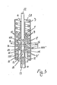
- This stem is placed coaxially inside the barrel and has at least externally a round and machined section and is fixed at the other end (see fig. 3) to a piston 5 that can slide with lateral tightness in a cylinder 6 closed at the ends by plugs 7-7' which are axially and with lateral tightness crossed respectively by the above mentioned stem 4 and by a tubular, round-section stem 8 axially aligned to parts 5-4 and having an external diameter equal to that of stem 4. Therefore, inside cylinder 6 there are two pressure chambers A and B, defined by the two faces of piston 5, that have a perfectly identical section. These chambers are completely filled with oil or other suitable liquid.
- gaskets 9-9' can be combined or replaced with sealing agents or adhesives.
- the stems 4-8 ends are preferably fixed to coaxial and opposed bar holds 105-105' with which piston 5 is enbloc and coaxially provided, such an assemblage 5-105-105' being provided with an axial hole 11, the diameter of which is equal to the inner diameter of stem 4, while it is inferior to that of stem 8, so that at the lower end of bar hold 105' there remains free a ring step 12 which will be dealt with later.
- Holes 14-14' are radially cut at the tapered ends of the piston. These holes open into above mentioned hole 11 through which the hydraulic connection between pressure chambers A and B of the cylinder-piston unit can be realized.
- a cylindrical round-section box 15 is fitted in hole 11 sufficiently snugly, but with the possibility to slide axially in it.
- the intermediate part of such box is equipped with a ring recess 16 of regular-symmetrical shape (see hereafter) being at least or substantially as long as the distance between centers of A/M holes 14-14'.
- box 15 is provided with ring gaskets 17-17' for laterally tight cooperation with the wall of hole 11. Gaskets 17' are more distant from ring recess 16 than gaskets 17, so that between parts 16-17' the box itself shows a section 115 of its pitch diameter.
- Box 15 protrudes with its lower end inside stem 8 and at this end it bears enbloc a head 18 which beats against the above mentioned step 12 under the stress of an elastic device 19.
- the section 115 of box 15 cooperates with a ring gasket 20 placed in a ring recess obtained in the intermediate part of hole 11 so that it appears equally distant from holes 14-14'.
- the above mentioned elastic device 19 is a garter spring fitted on stem 8 and maintained in the appropriate calibration ratio by a spacing bar 21 fixed on stem 8 for example by means of centripetal bending of the lower end of such device, as indicated with 108.
- the spacing bar 21 is preferably axially hollow, as indicated with 121, in order to avoid forming of pressure or vacuum at the bottom of box 15, which could compromise the smooth working of this device.
- Box 15 can be moved axially downwards, with a stroke of suitable length, by means of a rod 22 that axially crosses stem 4 and that protrudes from it and from barrel 3 with a section provided at the end with a head 122.
- Rod 22 can be structurally separated from box 15 or fastened to it or be enbloc with it.
- stems 4 and 8 must be refined only on the lateral outer surface which is meant to cooperate in tightness with plugs 7-7'.
- the inner surface of stems 4-8 can be unrefined instead as, for the purpose in question, only hole 11 together with box 15 need to be refined.
- Stems 4 and 8 are of such length that they remain in the necessary lateral tightness condition with the relative plugs, when piston 5 beats against the plugs 7-7', as per figures 1 and 2. As an indication, it is pointed out that,when stem 4 is completely extended from cylinder 6, the unit 4-6 shows a length which is substantially equal to that of barrel 3.
- a helical spring 25, with suitable characteristics, is fitted inside pipe 23 and the bottom end 123 of the pipe 23 is bent towards the center so that the pipe doesn't come out of the thickened part 124 of pin 24.
- This bottom part of the pin is equipped with a ring collar 224 weighing upon an axial thrust bearing 26 placed at the bottom of sheath 1. Pin 24 crosses this bearing, passes with clearance through a hole obtained at the bottom of sheath 1 and is constrained to the bottom 101, with sufficient clearance, by means of an elastic ring 27.
- Pipe 23 preferably presents an outside diameter equal or substantially equal to that of cylinder 6 and such as to leave between these parts and telescopic unit 1-3 a hollow space of such a width as to enable coaxial placing of a garter spring 28, with suitable characteristics, that with its upper end lies on a conical ring 29 centered on top of barrel 3, while with its bottom end the spring 28 lies on bearing 26.
- box 15 is hindered only by the action of spring 19 and can take place easily even if chamber A is under pressure (owing to the weight of the person sitting in the chair equipped with the structure in question), as thanks to the symmetric and regular form of recess 16, the axial movement of box 14 doesn't appear to be affected by the pressure exerted by transfer oil between chambers A and B (or viceversa).
- spring 19 brings box 15 back to closed position and the system automatically returns to block position.
- Rod 22 can be partly threaded and screwed to a correspondingly threaded part of stem 4, so that the axial movement of box 15 takes place in consequence of a rotation given to rod 22.
- elastic devices are provided for even in this case, wire springs for example, in order to bring rod 22 automatically back to rest position when left free, so as to permit automatic return of box 15 to block position.
- box 15 can be supplied without thickening of head 18 and can be fitted in an upside-down version as compared to the solution shown in the drawings, so that it can be operated in opening, with axial movement upwards in contrast with the action of an outer spring that would tend to stress it downwards, in the condition of interception of holes 14-14'. In this case box 15 would be fastened or integral with control rod 22.
- a hydropneumatic compensator or any other kind of compensator normally used for the same purpose in hydraulic shock-absorbers can be installed inside at least one of the pressure chambers A-B.
- the system as described above is extremely reliable. This doesn't prevent, however, other suitable interception means from being integrated in piston 5, preferably in combination with those described, in order to further improve the reliability of the unit.
- Box 15, with its inclined-plane shaped parts could for example be used as linear cam to open and close a small tap that controls the passage of liquid between chambers A and B, and closes automatically when the box itself is left free and returns to block position.
- holes 14-14' may be different in number and placed in a different manner on piston 5 or on parts close to it.
- Seal gaskets can also be different in number and of a quality different from those schematically shown in the drawings.
Landscapes
- Chairs Characterized By Structure (AREA)
- Accommodation For Nursing Or Treatment Tables (AREA)
- Fluid-Damping Devices (AREA)
Applications Claiming Priority (2)
| Application Number | Priority Date | Filing Date | Title |
|---|---|---|---|
| IT346285 | 1985-06-11 | ||
| IT8503462A IT8503462A0 (it) | 1985-06-11 | 1985-06-11 | Struttura regolabile in lunghezza mediante un dispositivo idraulico interno,e circuito chiuso particolarmente adatta come struttura di montante per il supporto del piano di sedile d'una poltrona |
Publications (2)
| Publication Number | Publication Date |
|---|---|
| EP0211809A2 true EP0211809A2 (fr) | 1987-02-25 |
| EP0211809A3 EP0211809A3 (fr) | 1987-07-22 |
Family
ID=11107824
Family Applications (1)
| Application Number | Title | Priority Date | Filing Date |
|---|---|---|---|
| EP86830151A Withdrawn EP0211809A3 (fr) | 1985-06-11 | 1986-06-05 | Structure réglable en longueur au moyen d'un dispositif hydraulique à circuit fermé interne, notamment une structure de colonne verticale d'un support de siège d'une chaise |
Country Status (4)
| Country | Link |
|---|---|
| EP (1) | EP0211809A3 (fr) |
| JP (1) | JPS6263230A (fr) |
| ES (1) | ES8703976A1 (fr) |
| IT (1) | IT8503462A0 (fr) |
Cited By (1)
| Publication number | Priority date | Publication date | Assignee | Title |
|---|---|---|---|---|
| EP0459955A1 (fr) * | 1990-05-21 | 1991-12-04 | SKILLMATIC S.r.l. | Cylindre de longueur variable, notamment pour chaises, sièges et similaires |
Family Cites Families (1)
| Publication number | Priority date | Publication date | Assignee | Title |
|---|---|---|---|---|
| DE3322796A1 (de) * | 1983-06-24 | 1985-01-03 | Eckard St. Margrethen Hansen | Federelement |
-
1985
- 1985-06-11 IT IT8503462A patent/IT8503462A0/it unknown
-
1986
- 1986-06-05 EP EP86830151A patent/EP0211809A3/fr not_active Withdrawn
- 1986-06-11 JP JP61133970A patent/JPS6263230A/ja active Pending
- 1986-06-11 ES ES555955A patent/ES8703976A1/es not_active Expired
Cited By (1)
| Publication number | Priority date | Publication date | Assignee | Title |
|---|---|---|---|---|
| EP0459955A1 (fr) * | 1990-05-21 | 1991-12-04 | SKILLMATIC S.r.l. | Cylindre de longueur variable, notamment pour chaises, sièges et similaires |
Also Published As
| Publication number | Publication date |
|---|---|
| JPS6263230A (ja) | 1987-03-19 |
| IT8503462A0 (it) | 1985-06-11 |
| ES8703976A1 (es) | 1987-03-01 |
| EP0211809A3 (fr) | 1987-07-22 |
| ES555955A0 (es) | 1987-03-01 |
Similar Documents
| Publication | Publication Date | Title |
|---|---|---|
| US4245826A (en) | Resilient column of adjustable length | |
| US4373707A (en) | Construction including a gas spring | |
| JPH08511190A (ja) | 人工膝関節のためのスウィングフェイズ制御 | |
| CA2170172A1 (fr) | Articulation pour le genou produisant un effet de freinage | |
| US4595179A (en) | Hyraulic damping device and artificial joint employing the device | |
| US4997150A (en) | Adjustable oleopneumatic support | |
| ES8608413A1 (es) | Amortiguador de choques hidraulico y regulable | |
| WO2020115642A4 (fr) | Amortisseur hydraulique avec un organe d'arrêt hydraulique fonctionnant pendant la course de compression de l'amortisseur et avec un dispositif de réglage pour régler le comportement de l'organe d'arrêt hydraulique en fonction de la charge du véhicule | |
| GB1526856A (en) | Lockable supporting spring unit | |
| EP0211809A2 (fr) | Structure réglable en longueur au moyen d'un dispositif hydraulique à circuit fermé interne, notamment une structure de colonne verticale d'un support de siège d'une chaise | |
| AU2152197A (en) | Hydraulic lifting-lowering-system for a working table, a couch or lying furniture or another heavy object | |
| GB2343848A (en) | Control unit for prosthesis | |
| US4438910A (en) | Shock absorbing snubber for derrick hooks | |
| CN211175172U (zh) | 一种可调节双向气弹簧 | |
| FR2457402A1 (fr) | Dispositif de manoeuvre du type a cylindre et tige de piston et actionne par un fluide | |
| US4178655A (en) | Counterbalance mechanism | |
| US2695777A (en) | Hydraulic metering device | |
| US2940433A (en) | Hydraulic valve tappet | |
| DE808745C (de) | Hydraulische Stuhlsaeule | |
| KR101084699B1 (ko) | 운동기구용 유압실린더의 제어장치 | |
| SU1542773A1 (ru) | Гидравлическое устройство дл выпрессовки гладких втулок | |
| DE102007015992B4 (de) | Gasfeder | |
| CN210344401U (zh) | 一种高精度等量分配阀结构 | |
| US4331186A (en) | Safety push rod assemblies | |
| US2063802A (en) | Automatic rod line adjuster |
Legal Events
| Date | Code | Title | Description |
|---|---|---|---|
| PUAI | Public reference made under article 153(3) epc to a published international application that has entered the european phase |
Free format text: ORIGINAL CODE: 0009012 |
|
| AK | Designated contracting states |
Kind code of ref document: A2 Designated state(s): CH DE FR GB LI NL SE |
|
| PUAL | Search report despatched |
Free format text: ORIGINAL CODE: 0009013 |
|
| AK | Designated contracting states |
Kind code of ref document: A3 Designated state(s): CH DE FR GB LI NL SE |
|
| STAA | Information on the status of an ep patent application or granted ep patent |
Free format text: STATUS: THE APPLICATION IS DEEMED TO BE WITHDRAWN |
|
| 18D | Application deemed to be withdrawn |
Effective date: 19880125 |
|
| RIN1 | Information on inventor provided before grant (corrected) |
Inventor name: PIRETTI, GIANCARLO |