EP0211976A1 - Procédé pour la fabrication d'un senseur optique - Google Patents
Procédé pour la fabrication d'un senseur optique Download PDFInfo
- Publication number
- EP0211976A1 EP0211976A1 EP85110149A EP85110149A EP0211976A1 EP 0211976 A1 EP0211976 A1 EP 0211976A1 EP 85110149 A EP85110149 A EP 85110149A EP 85110149 A EP85110149 A EP 85110149A EP 0211976 A1 EP0211976 A1 EP 0211976A1
- Authority
- EP
- European Patent Office
- Prior art keywords
- core
- bore
- cladding
- optical waveguide
- waveguide
- Prior art date
- Legal status (The legal status is an assumption and is not a legal conclusion. Google has not performed a legal analysis and makes no representation as to the accuracy of the status listed.)
- Granted
Links
Images



Classifications
-
- B—PERFORMING OPERATIONS; TRANSPORTING
- B29—WORKING OF PLASTICS; WORKING OF SUBSTANCES IN A PLASTIC STATE IN GENERAL
- B29C—SHAPING OR JOINING OF PLASTICS; SHAPING OF MATERIAL IN A PLASTIC STATE, NOT OTHERWISE PROVIDED FOR; AFTER-TREATMENT OF THE SHAPED PRODUCTS, e.g. REPAIRING
- B29C48/00—Extrusion moulding, i.e. expressing the moulding material through a die or nozzle which imparts the desired form; Apparatus therefor
- B29C48/15—Extrusion moulding, i.e. expressing the moulding material through a die or nozzle which imparts the desired form; Apparatus therefor incorporating preformed parts or layers, e.g. extrusion moulding around inserts
- B29C48/156—Coating two or more articles simultaneously
-
- B—PERFORMING OPERATIONS; TRANSPORTING
- B29—WORKING OF PLASTICS; WORKING OF SUBSTANCES IN A PLASTIC STATE IN GENERAL
- B29C—SHAPING OR JOINING OF PLASTICS; SHAPING OF MATERIAL IN A PLASTIC STATE, NOT OTHERWISE PROVIDED FOR; AFTER-TREATMENT OF THE SHAPED PRODUCTS, e.g. REPAIRING
- B29C48/00—Extrusion moulding, i.e. expressing the moulding material through a die or nozzle which imparts the desired form; Apparatus therefor
- B29C48/03—Extrusion moulding, i.e. expressing the moulding material through a die or nozzle which imparts the desired form; Apparatus therefor characterised by the shape of the extruded material at extrusion
- B29C48/06—Rod-shaped
-
- B—PERFORMING OPERATIONS; TRANSPORTING
- B29—WORKING OF PLASTICS; WORKING OF SUBSTANCES IN A PLASTIC STATE IN GENERAL
- B29C—SHAPING OR JOINING OF PLASTICS; SHAPING OF MATERIAL IN A PLASTIC STATE, NOT OTHERWISE PROVIDED FOR; AFTER-TREATMENT OF THE SHAPED PRODUCTS, e.g. REPAIRING
- B29C48/00—Extrusion moulding, i.e. expressing the moulding material through a die or nozzle which imparts the desired form; Apparatus therefor
- B29C48/03—Extrusion moulding, i.e. expressing the moulding material through a die or nozzle which imparts the desired form; Apparatus therefor characterised by the shape of the extruded material at extrusion
- B29C48/09—Articles with cross-sections having partially or fully enclosed cavities, e.g. pipes or channels
-
- A—HUMAN NECESSITIES
- A61—MEDICAL OR VETERINARY SCIENCE; HYGIENE
- A61B—DIAGNOSIS; SURGERY; IDENTIFICATION
- A61B1/00—Instruments for performing medical examinations of the interior of cavities or tubes of the body by visual or photographical inspection, e.g. endoscopes; Illuminating arrangements therefor
- A61B1/00163—Optical arrangements
- A61B1/00165—Optical arrangements with light-conductive means, e.g. fibre optics
-
- B—PERFORMING OPERATIONS; TRANSPORTING
- B29—WORKING OF PLASTICS; WORKING OF SUBSTANCES IN A PLASTIC STATE IN GENERAL
- B29L—INDEXING SCHEME ASSOCIATED WITH SUBCLASS B29C, RELATING TO PARTICULAR ARTICLES
- B29L2011/00—Optical elements, e.g. lenses, prisms
- B29L2011/0075—Light guides, optical cables
Definitions
- the present invention relates to a method for producing an optical sensor. More particularly, it relates to a method for producing an optical sensor comprising a core acting as an optical waveguide part for illumination, a cladding surrounding the core and having a refractive index lower than that of the core and an image fiber which is inserted in an elongate bore formed in the core along the entire length of the sensor, or embedded in the core.
- An optical sensor is a light- or image-transmitting elongate element comprising an optical waveguide, an image fiber and optionally an elongate hollow tube member for transporting a fluid.
- Such the optical sensor is often used as a light transmitting element of an endoscope for inspecting an interior of an organ such as an abdomen, a heart or a blood vessel.
- the optical sensor is introduced in a human or mammal body to be inspected together with an image pick up adapter which comprises a lens and forms an image of the organ interior on a front end of the image fiber.
- an image pick up adapter which comprises a lens and forms an image of the organ interior on a front end of the image fiber.
- the endoscope comprises an image-receiving apparatus for monitoring the image propagated through the image fiber. The image is directly observed by means of an orthoptic adaptor or projected on a monitoring television.
- a light source attached at the near end of the optical waveguide emits light, which is propagated through the optical waveguide and illuminates the organ interior.
- the conventional optical waveguide comprises bundled transparent plastic optical fibers each having a round cross section. However, gaps are formed between the adjacent optical fibers, and light is not propagated through the gaps. This reduces an effective volume of the optical waveguide.
- a hollow tube is additionally assembled in the optical sensor to remove a fluids such as blood from the organ interior or to inject physiologic saline in a small balloon attached to the front end of the sensor so as to inflate the balloon and exclude the blood from a part to be observed. Air in the balloon is exhausted through an additional tube provided in the sensor.
- Fig. 1 shows a conventional sensor having an image fiber 1, plural optical fibers 2 as optical waveguides and two tubes 3 all of which are enclosed in a cladding 4. Such the sensor also has gaps between the waveguides and/or the tubes.
- the sensor containing the optical waveguide and the image fiber has a cross section as shown in Fig. 2, 3 or 4.
- the sensor of Fig. 2 has one bore 6 having a cladding layer 5 through which an image fiber is inserted, that of Fig. 2 has three bores 6 each having a cladding layer 5 through one of which an image fiber is inserted, and that of Fig. 4 has one image fiber 1 and two vacant bores 6.
- the bore is formed in the waveguide by extruding a core material from a coextrusion die with supplying at least one metal wire, simultaneously extruding a cladding material around the core material to form a cylindrical waveguide with the metal wire embedded and removing the metal wire after stretching it to form a bore in the core.
- the inner diameter of the die and the outer diameter of the metal wire should be extremely precise since the former determines the outer diameter of the waveguide and the latter determines the inner diameter of the bore.
- the methods include many steps including the removal of the metal wire. Further, marks are generated on the inner surface of the bore during the removal of the metal wire. Since the inner surface of the bore should be coated with a material having a smaller refractive index than that of the waveguide (core) material so as to reflect light to be transmitted, the metal wire should be coated by such the material before extrusion of the core material. This makes the structure of the die more complicate.
- One object of the present invention is to provide an improved method for producing an optical sensor comprising a core acting as an optical waveguide part, a cladding surrounding the core and an image fiber inserted in a bore formed in the core.
- Another object of the present invention is to provide an improved method for producing an optical sensor having an enlarged effective cross sectional area of the optical waveguide.
- Further object of the present invention is to provide a novel optical sensor comprising a core acting as an optical waveguide part and having a bore extending along the entire length of the sensor, a cladding surrounding the core, and an image fiber embedded in the core.
- the core of the sensor to be produced by the method of the invention is usually made of a transparent amorphous polymeric material optionally added with a plasticizer.
- the core material are homo- or co-polymer of styrene or methacrylate (e.g., polymethyl methacrylate, n-butyl methacrylate/isobutyl methacrylate copolymer and the like), polymethyl methacrylate plasticized with adipate, and polycarbonate.
- the core is surrounded by a cladding to confine the propagated light in the core.
- the cladding is made of a material having a smaller refractive index than that of the core material such as fluororesin (e.g., homo- or co-polymer of vinylidene fluoride or tetrafluoroethylene), silicone resin and ethylene/vinyl acetate copolymer.
- the optical sensor has an outer diameter of 0.25 to 2.2 mm, the cladding has a thickness of 0.01 to 0.04, and the bore has a diameter up to 1.5 mm.
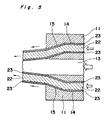
- the optical waveguide is produced by means of a coextrusion die shown in Fig. 5.
- the die 11 has an aperture 13 and an inlet 14 for the core and cladding materials coaxially surrounding the aperture 13.
- a frustoconical slant channel 15 is provided with.
- the tip of the channel 15 opens near the front end of the aperture 13.
- the core material 22 and the cladding material 23 are fed into the inlet 14. Simultaneously, a suitable volume of air is injected through the aperture 13 at suitable pressure.
- the core and cladding materials are coextruded in the form of a tube a central hollow portion of which is formed by injected air.
- the thus produced optical waveguide has a cross section as shown in Fig. 2, wherein the inner and outer surfaces of the core 2 are coated by the cladding material 4,5. Through the bore 6, an image fiber is inserted to form an optical sensor.
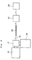
- Fig. 6 schematically shows an equipment for producing the optical waveguide of Fig. 2.
- the core and cladding materials are fed in a coextrusion die part 17 having the die 11 of Fig. 5 from extruders 16 and 18, respectively.
- a fiber 19 extruded from the die is cooled in a cooling zone 20, and drawn by a capstan puller 21 and finally wound by a winder 22.
- the outer diameter of the fiber 19 is controlled by adjusting the puling rate of the capstan 21 and the fed amounts of the core and cladding materials.
- a waveguide having two or more bores in the core can be produced by means of a suitable die having two or more apertures for injecting air.
- the optical waveguide is produced by coextruding the core and cladding materials with supplying at least one metal wire in the core material to form an optical waveguide having the metal wire embedded, removing the wire from the fiber after stretching it and drawing the waveguide at a temperature higher than a glass transition temperature of the core material.
- a metal wire 31 is supplied from a supplier 30 to a die 32, and the core and cladding materials are supplied from an extruder 32' and coated around the metal wire 31.
- Two or more metal wires may be supplied to finally produce an optical waveguide having two or more bores.
- An optical waveguide 33 with the metal wire is wound by a winder 34.
- the metal wire is removed from the optical waveguide.
- the optical waveguide 34 without the wire is unwound from a supplier 35 and wound by a winder 39 through a roll 35 for controlling a supply rate, a heating means 37 and a roll 38 for controlling a winding rate.
- the heating means 37 may be a furnace, a water or oil bath or a heating roll.
- the optical waveguide is heated at a temperature higher than the glass transition temperature of the core material by 10 to 50°C.
- the drawn rate of the optical waveguide is controlled by adjusting the supply rate and the winding rate. Usually, the waveguide is drawn by a factor of 2 to 3.
- the metal wire is made of a rigid flexible metal such as annealed copper wire.
- the waveguide is produced by substantially the same manner as in the second embodiment but using a hollow fiber in place of the metal wire and not drawing the waveguide.
- the hollow fiber forms the bore of the optical waveguide.
- the hollow fiber is made of a thermoplastic resin (e.g, polyamide, polysulfone, polyethersulfone, polyetherimide, polyvinylidene fluoride, polytetrafluoroethylene, tetrafluoroethylene/hexafluoropropylene copolymer and the like), a thermoset resin (e.g., polyesterimide, polyamideimide, polyimide and the like), quartz glass, multicomponent glass, metal (e.g., gold, silver, copper, aluminum, stainless steel and the like). Because of flexibility, the resins are preferable.
- a thermoplastic resin e.g, polyamide, polysulfone, polyethersulfone, polyetherimide, polyvinylidene fluoride, polytetrafluoroethylene, tetrafluoroethylene/hexafluoropropylene copolymer and the like
- a thermoset resin e.g., polyesterimide, polyamideimide
- an image fiber may be supplied together with the hollow fiber.
- Two hollow fibers 41 are continuously supplied from corresponding hollow fiber suppliers 42 to a coextrusion die 40.
- An image fiber 1 is continuously supplied from an image fiber supplier 43 to the coextrusion die 1.
- Distance between the two hollow fibers 7 is controlled by means of a pair of guide rolls 44.
- the coextrusion die is attached to a head of an extruder consisting of extruders 45,46 for the core material and the cladding material, respectively.
- Fig. 10 shows an enlarged cross section of a die 10, which has apertures 51 for forwarding the respective hollow fiber and an aperture (not shown) for forwarding the image fiber 1.
- the core material A is cylindrically extruded around the hollow fibers 41 and the image fiber 1 and then a cladding material B is applied around the core material to form an optical waveguide comprising a core 52 and a cladding 53. Then, the cladding is sized to form an optical sensor of Fig. 11.
- the optical sensor extruded from the die 10 is cooled in a cooling zone 47 to solidify the cladding material.
- a capstan puller 48 and a winder 49 are provided with.
- Extrusion conditions are so selected that the thermal deformation of the hollow fiber is prevented during extrusion of the core and cladding materials.
- the hollow fiber is made of a material having a deformation temperature higher than the extrusion temperature of the core material preferably by at least 10°C.
- This method can be modified by replacing the image fiber with a third hollow fiber.
- the image fiber is inserted in one of three hollow fibers. This modification is preferred since the image fiber is not subjected to a high temperature so that it is not thermally damaged.
- polymethyl methacrylate and vinylidene fluoride/tetrafluoroethylene copolymer were used, respectively.
- the optical waveguide was produced under following conditions: Extrusion rate of the resin: 20-40 cm3/min. Pulling rate: 5-10 m/min. Extrusion temperature: 240°C
- the produced waveguide had an outer diameter of 2.2 mm, a bore diameter of 1.5 mm and cladding thickness of 20 ⁇ m.
- an optical waveguide was produced under substantially the same conditions but the extrusion temperature being 150-200°C.
- a core material of polymethyl methacrylate (glass transition temperature, 105°C) and a cladding material of vinylidene fluoride/tetrafluoroethylene copolymer were extruded and applied around annealed copper wire having an outer diameter of 1.06 mm. Then, the copper wire was removed to form an optical waveguide having an outer diameter of 1.70 mm and a bore diameter of 1.06 mm.
- the produced optical waveguide was drawn with a draw ratio of two in a furnace kept at 140°C to produce the waveguide having an outer diameter of 1.2 mm and a bore diameter of 0.75 mm. Its physical properties are shown in Table.
- an image sensor could be produced by inserting an image fiber in the bore of the waveguide.
- An optical sensor was produced by means of the die of Fig. 10.
Landscapes
- Engineering & Computer Science (AREA)
- Mechanical Engineering (AREA)
- Optical Fibers, Optical Fiber Cores, And Optical Fiber Bundles (AREA)
Priority Applications (2)
| Application Number | Priority Date | Filing Date | Title |
|---|---|---|---|
| DE8585110149T DE3574238D1 (en) | 1985-08-13 | 1985-08-13 | Method for producing an optical sensor |
| EP85110149A EP0211976B1 (fr) | 1985-08-13 | 1985-08-13 | Procédé pour la fabrication d'un senseur optique |
Applications Claiming Priority (1)
| Application Number | Priority Date | Filing Date | Title |
|---|---|---|---|
| EP85110149A EP0211976B1 (fr) | 1985-08-13 | 1985-08-13 | Procédé pour la fabrication d'un senseur optique |
Publications (2)
| Publication Number | Publication Date |
|---|---|
| EP0211976A1 true EP0211976A1 (fr) | 1987-03-04 |
| EP0211976B1 EP0211976B1 (fr) | 1989-11-15 |
Family
ID=8193679
Family Applications (1)
| Application Number | Title | Priority Date | Filing Date |
|---|---|---|---|
| EP85110149A Expired EP0211976B1 (fr) | 1985-08-13 | 1985-08-13 | Procédé pour la fabrication d'un senseur optique |
Country Status (2)
| Country | Link |
|---|---|
| EP (1) | EP0211976B1 (fr) |
| DE (1) | DE3574238D1 (fr) |
Cited By (4)
| Publication number | Priority date | Publication date | Assignee | Title |
|---|---|---|---|---|
| FR2899087A1 (fr) * | 2006-04-03 | 2007-10-05 | V I M S Video Interventionnell | Protection pour endoscope et endoscope correspondant |
| US8611716B2 (en) | 2009-09-30 | 2013-12-17 | Corning Incorporated | Channeled substrates for integrated optical devices employing optical fibers |
| CN111788509A (zh) * | 2017-11-30 | 2020-10-16 | 光子科学研究所基金会 | 光学内窥镜 |
| WO2021120441A1 (fr) * | 2019-12-18 | 2021-06-24 | 安徽森泰木塑集团股份有限公司 | Moule de préparation de profil composite |
Citations (4)
| Publication number | Priority date | Publication date | Assignee | Title |
|---|---|---|---|---|
| FR2365999A1 (fr) * | 1976-09-30 | 1978-04-28 | Univ Southern California | Instrument pour examiner la surface interne d'une cavite du corps et executer simultanement une operation medicale sur cette surface, de l'exterieur du corps |
| GB1526777A (en) * | 1976-12-01 | 1978-09-27 | Pilkington Brothers Ltd | Method and apparatus for sheathing fibres |
| EP0097934A2 (fr) * | 1982-06-26 | 1984-01-11 | Sumitomo Electric Industries Limited | Cathéter transmetteur d'images à fibres optiques composées et procédé de fabrication |
| EP0100517A2 (fr) * | 1982-07-31 | 1984-02-15 | Sumitomo Electric Industries Limited | Capteur à fibres optiques |
-
1985
- 1985-08-13 EP EP85110149A patent/EP0211976B1/fr not_active Expired
- 1985-08-13 DE DE8585110149T patent/DE3574238D1/de not_active Expired
Patent Citations (4)
| Publication number | Priority date | Publication date | Assignee | Title |
|---|---|---|---|---|
| FR2365999A1 (fr) * | 1976-09-30 | 1978-04-28 | Univ Southern California | Instrument pour examiner la surface interne d'une cavite du corps et executer simultanement une operation medicale sur cette surface, de l'exterieur du corps |
| GB1526777A (en) * | 1976-12-01 | 1978-09-27 | Pilkington Brothers Ltd | Method and apparatus for sheathing fibres |
| EP0097934A2 (fr) * | 1982-06-26 | 1984-01-11 | Sumitomo Electric Industries Limited | Cathéter transmetteur d'images à fibres optiques composées et procédé de fabrication |
| EP0100517A2 (fr) * | 1982-07-31 | 1984-02-15 | Sumitomo Electric Industries Limited | Capteur à fibres optiques |
Non-Patent Citations (2)
| Title |
|---|
| PATENT ABSTRACTS OF JAPAN, vol. 9, no. 187 (M-401), 3rd August 1985, page 145 M 401; & JP - A - 60 54830 (SUMITOMO DENKI KOGYO K.K.) 29-03-1985 * |
| PATENT ABSTRACTS OF JAPAN, vol. 9, no. 187 (M-401), 3rd August 1985, page 146 M 401; & JP - A - 60 54833 (SUMITOMO DENKI KOGYO K.K.) 29-03-1985 * |
Cited By (12)
| Publication number | Priority date | Publication date | Assignee | Title |
|---|---|---|---|---|
| FR2899087A1 (fr) * | 2006-04-03 | 2007-10-05 | V I M S Video Interventionnell | Protection pour endoscope et endoscope correspondant |
| WO2007113400A1 (fr) * | 2006-04-03 | 2007-10-11 | V.I.M.S.Video Interventionnelle Medicale Scientifique | Protection pour endoscope et endoscope correspondant |
| JP2009532153A (ja) * | 2006-04-03 | 2009-09-10 | ベ.イ.エム.エス.ビデオ アンテルバンシオネル メディカル サイアンティフィク | 内視鏡用保護体及びこれに対応する内視鏡 |
| RU2435513C2 (ru) * | 2006-04-03 | 2011-12-10 | В.И.М.С. Видео Интервансионнелль Медикаль Сьентифик | Защитное устройство для эндоскопа и соответствующий эндоскоп |
| CN101466297B (zh) * | 2006-04-03 | 2012-12-19 | 视频医药科学治疗公司 | 内窥镜用保护装置及相应的内窥镜 |
| US8454501B2 (en) | 2006-04-03 | 2013-06-04 | V.I.M.S. Video Interventionnelle Medicale Scientifique | Protection for endoscope, and corresponding endoscope |
| AU2007232458B2 (en) * | 2006-04-03 | 2013-08-01 | V.I.M.S.Video Interventionnelle Medicale Scientifique | Protection for endoscope, and corresponding endoscope |
| AU2007232458B9 (en) * | 2006-04-03 | 2013-12-19 | V.I.M.S.Video Interventionnelle Medicale Scientifique | Protection for endoscope, and corresponding endoscope |
| US8611716B2 (en) | 2009-09-30 | 2013-12-17 | Corning Incorporated | Channeled substrates for integrated optical devices employing optical fibers |
| CN111788509A (zh) * | 2017-11-30 | 2020-10-16 | 光子科学研究所基金会 | 光学内窥镜 |
| US12282151B2 (en) | 2017-11-30 | 2025-04-22 | Fundació Institut De Ciències Fotòniques | Optical endoscope |
| WO2021120441A1 (fr) * | 2019-12-18 | 2021-06-24 | 安徽森泰木塑集团股份有限公司 | Moule de préparation de profil composite |
Also Published As
| Publication number | Publication date |
|---|---|
| DE3574238D1 (en) | 1989-12-21 |
| EP0211976B1 (fr) | 1989-11-15 |
Similar Documents
| Publication | Publication Date | Title |
|---|---|---|
| US4806289A (en) | Method of making a hollow light pipe | |
| US4172106A (en) | Optical fibre cables and their manufacture | |
| EP0097934B1 (fr) | Cathéter transmetteur d'images à fibres optiques composées et procédé de fabrication | |
| US5471553A (en) | Multicore hollow optical fiber and a method for preparation thereof | |
| US5898810A (en) | Illumination waveguide and method for producing same | |
| CA1200062A (fr) | Elements de cable optique | |
| JP3229044B2 (ja) | 中空多芯光ファイバ及びその先端異形体 | |
| AU7682894A (en) | Apparatus and method for sheathing optical fibers | |
| EP0211976B1 (fr) | Procédé pour la fabrication d'un senseur optique | |
| GB1526777A (en) | Method and apparatus for sheathing fibres | |
| US4552434A (en) | Crystalline infrared optical fiber with a small gap and a process for the production of same | |
| US6171526B1 (en) | Method for making a grooved spacer for a telecommunications cable | |
| EP0173266A2 (fr) | Guide d'ondes optiques composé et sa fabrication | |
| JPS6054830A (ja) | 光学的センサの製造方法 | |
| US20050056952A1 (en) | Method of manufacturing multi-polymer optical fiber cable | |
| GB2079970A (en) | Improvements in or relating to optical cable elements | |
| EP0229202A1 (fr) | Guide d'ondes optique et son procédé de fabrication | |
| JP3102910B2 (ja) | 中空導光繊維 | |
| US4871499A (en) | Method of molding a flexible tube of low thermal longitudinal coefficient of expansion | |
| JPS6186720A (ja) | 光学的センサの製造方法と装置 | |
| JPS60169805A (ja) | 光学的センサおよびその製造方法 | |
| JPS613105A (ja) | 光学的センサの製造方法 | |
| JPH07256779A (ja) | 繊維強化熱可塑性樹脂複合管の製造方法 | |
| CA1290602C (fr) | Guide de lumiere d'eclairage et fabrication de ce guide | |
| JPS6054833A (ja) | ライトガイド製作用ダイス |
Legal Events
| Date | Code | Title | Description |
|---|---|---|---|
| PUAI | Public reference made under article 153(3) epc to a published international application that has entered the european phase |
Free format text: ORIGINAL CODE: 0009012 |
|
| AK | Designated contracting states |
Kind code of ref document: A1 Designated state(s): DE FR GB |
|
| 17P | Request for examination filed |
Effective date: 19870424 |
|
| 17Q | First examination report despatched |
Effective date: 19880208 |
|
| GRAA | (expected) grant |
Free format text: ORIGINAL CODE: 0009210 |
|
| AK | Designated contracting states |
Kind code of ref document: B1 Designated state(s): DE FR GB |
|
| REF | Corresponds to: |
Ref document number: 3574238 Country of ref document: DE Date of ref document: 19891221 |
|
| ET | Fr: translation filed | ||
| PLBE | No opposition filed within time limit |
Free format text: ORIGINAL CODE: 0009261 |
|
| STAA | Information on the status of an ep patent application or granted ep patent |
Free format text: STATUS: NO OPPOSITION FILED WITHIN TIME LIMIT |
|
| 26N | No opposition filed | ||
| PGFP | Annual fee paid to national office [announced via postgrant information from national office to epo] |
Ref country code: GB Payment date: 19930730 Year of fee payment: 9 |
|
| PGFP | Annual fee paid to national office [announced via postgrant information from national office to epo] |
Ref country code: FR Payment date: 19930805 Year of fee payment: 9 |
|
| PGFP | Annual fee paid to national office [announced via postgrant information from national office to epo] |
Ref country code: DE Payment date: 19930806 Year of fee payment: 9 |
|
| PG25 | Lapsed in a contracting state [announced via postgrant information from national office to epo] |
Ref country code: GB Effective date: 19940813 |
|
| GBPC | Gb: european patent ceased through non-payment of renewal fee |
Effective date: 19940813 |
|
| PG25 | Lapsed in a contracting state [announced via postgrant information from national office to epo] |
Ref country code: FR Effective date: 19950428 |
|
| PG25 | Lapsed in a contracting state [announced via postgrant information from national office to epo] |
Ref country code: DE Effective date: 19950503 |
|
| REG | Reference to a national code |
Ref country code: FR Ref legal event code: ST |