EP0212003A1 - Schutzvorrichtung für Wärmetauscher in einem Rohr für mit feinen Aschenteilchen beladenen Rauch - Google Patents
Schutzvorrichtung für Wärmetauscher in einem Rohr für mit feinen Aschenteilchen beladenen Rauch Download PDFInfo
- Publication number
- EP0212003A1 EP0212003A1 EP85115670A EP85115670A EP0212003A1 EP 0212003 A1 EP0212003 A1 EP 0212003A1 EP 85115670 A EP85115670 A EP 85115670A EP 85115670 A EP85115670 A EP 85115670A EP 0212003 A1 EP0212003 A1 EP 0212003A1
- Authority
- EP
- European Patent Office
- Prior art keywords
- parallel
- sections
- networks
- flow
- tubes
- Prior art date
- Legal status (The legal status is an assumption and is not a legal conclusion. Google has not performed a legal analysis and makes no representation as to the accuracy of the status listed.)
- Granted
Links
- 239000000779 smoke Substances 0.000 title abstract description 4
- 230000001681 protective effect Effects 0.000 title description 2
- UGFAIRIUMAVXCW-UHFFFAOYSA-N Carbon monoxide Chemical compound [O+]#[C-] UGFAIRIUMAVXCW-UHFFFAOYSA-N 0.000 claims abstract description 6
- 239000003546 flue gas Substances 0.000 claims abstract description 6
- 239000010419 fine particle Substances 0.000 claims abstract description 5
- 239000003517 fume Substances 0.000 claims description 4
- 239000003245 coal Substances 0.000 abstract description 3
- 239000002956 ash Substances 0.000 description 6
- 230000003628 erosive effect Effects 0.000 description 4
- 238000009825 accumulation Methods 0.000 description 1
- 239000010883 coal ash Substances 0.000 description 1
- 230000000694 effects Effects 0.000 description 1
- 239000000463 material Substances 0.000 description 1
- 239000002184 metal Substances 0.000 description 1
- 238000011144 upstream manufacturing Methods 0.000 description 1
Images



Classifications
-
- F—MECHANICAL ENGINEERING; LIGHTING; HEATING; WEAPONS; BLASTING
- F28—HEAT EXCHANGE IN GENERAL
- F28D—HEAT-EXCHANGE APPARATUS, NOT PROVIDED FOR IN ANOTHER SUBCLASS, IN WHICH THE HEAT-EXCHANGE MEDIA DO NOT COME INTO DIRECT CONTACT
- F28D21/00—Heat-exchange apparatus not covered by any of the groups F28D1/00 - F28D20/00
- F28D21/0001—Recuperative heat exchangers
- F28D21/0003—Recuperative heat exchangers the heat being recuperated from exhaust gases
- F28D21/0005—Recuperative heat exchangers the heat being recuperated from exhaust gases for domestic or space-heating systems
- F28D21/0007—Water heaters
-
- F—MECHANICAL ENGINEERING; LIGHTING; HEATING; WEAPONS; BLASTING
- F16—ENGINEERING ELEMENTS AND UNITS; GENERAL MEASURES FOR PRODUCING AND MAINTAINING EFFECTIVE FUNCTIONING OF MACHINES OR INSTALLATIONS; THERMAL INSULATION IN GENERAL
- F16L—PIPES; JOINTS OR FITTINGS FOR PIPES; SUPPORTS FOR PIPES, CABLES OR PROTECTIVE TUBING; MEANS FOR THERMAL INSULATION IN GENERAL
- F16L55/00—Devices or appurtenances for use in, or in connection with, pipes or pipe systems
- F16L55/02—Energy absorbers; Noise absorbers
- F16L55/027—Throttle passages
-
- F—MECHANICAL ENGINEERING; LIGHTING; HEATING; WEAPONS; BLASTING
- F16—ENGINEERING ELEMENTS AND UNITS; GENERAL MEASURES FOR PRODUCING AND MAINTAINING EFFECTIVE FUNCTIONING OF MACHINES OR INSTALLATIONS; THERMAL INSULATION IN GENERAL
- F16L—PIPES; JOINTS OR FITTINGS FOR PIPES; SUPPORTS FOR PIPES, CABLES OR PROTECTIVE TUBING; MEANS FOR THERMAL INSULATION IN GENERAL
- F16L57/00—Protection of pipes or objects of similar shape against external or internal damage or wear
-
- F—MECHANICAL ENGINEERING; LIGHTING; HEATING; WEAPONS; BLASTING
- F28—HEAT EXCHANGE IN GENERAL
- F28F—DETAILS OF HEAT-EXCHANGE AND HEAT-TRANSFER APPARATUS, OF GENERAL APPLICATION
- F28F19/00—Preventing the formation of deposits or corrosion, e.g. by using filters or scrapers
-
- F—MECHANICAL ENGINEERING; LIGHTING; HEATING; WEAPONS; BLASTING
- F28—HEAT EXCHANGE IN GENERAL
- F28F—DETAILS OF HEAT-EXCHANGE AND HEAT-TRANSFER APPARATUS, OF GENERAL APPLICATION
- F28F9/00—Casings; Header boxes; Auxiliary supports for elements; Auxiliary members within casings
- F28F9/005—Other auxiliary members within casings, e.g. internal filling means or sealing means
Definitions
- the present invention relates to a device for protecting exchangers placed in a flue pipe loaded with fine particles of ash.
- These horizontal or vertical exchangers are formed by parallel networks between them comprising a main zone equipped with straight tubes perpendicular to the flue gas flow and two reduced end zones equipped with bends and sections of tubes parallel to the flow fumes.
- the average speed of smoke circulation at the exchangers is generally limited between 10 and 15 m / s to avoid erosion of the tubes by coal ash, the abrasiveness of which, depending on the nature of the coal, can be high.
- the end zones have a lower pressure drop coefficient than that of the zone main.
- they are generally the seat of significant local overspeeds, which can reach for example twice the average speed of circulation due to the dimensioning, causing local erosion of the tubes. This results in major repair work which is expensive and which affects the availability of the boiler.
- the devices of the prior art are generally obstacles placed upstream of the exchangers and essentially having a baffle effect. These devices only protect the entry of the exchangers and therefore do not provide total protection of these. In addition, at the end of these obstacles, a large overspeed zone may form which may be accompanied by significant concentrations of ash, sources of local erosion.
- the object of the present invention is to provide complete protection of the exchangers, while avoiding any local overspeed zone and any zone of ash concentrations.
- the subject of the present invention is a device for protecting exchangers placed in a flue pipe loaded with fine particles of ash, these exchangers being formed by networks which are parallel to each other comprising a main zone equipped with sections of straight tubes perpendicular to the flue gas flow and two end zones equipped with elbows and sections of straight tubes parallel to the flow, characterized in that it consists of panels parallel to each other and parallel to the networks of tubes, each panel being placed between two networks and at each end zone.
- This device is designed so as to reconstitute in the area considered a pressure drop coefficient at least equivalent to that existing in the main area of the networks.
- each panel consists of an assembly, the active part of which represents, vis-à-vis the fumes, an obstacle substantially equivalent to the obstacle represented by the main zone consisting of sections of straight tubes perpendicular to the flow.
- each panel has the general shape of a triangle covering the sections of straight tubes parallel to the flow.
- each panel has the general shape of a rectangle covering an entire end zone.
- Figure 1 there is shown the duct 1 and a single network 10 consisting of tubes, the arrow F representing the direction of the flue gas flow.
- Each tube has several straight sections 11 perpendicular to the flue gas flow, several bends 12 and several straight sections 13 parallel to the flow. All the straight sections 11 perpendicular to the flow represent a main zone A. All the elbows 12 and all the straight sections 13 parallel to the flow represent two end zones B where the risks of erosion are located.
- FIG. 2 shows the section of the duct 1 and the position of all the networks 10 of tubes placed parallel to each other.
- the present invention therefore consists in placing protective devices at each end B and between all the spaces left free between two networks 10.
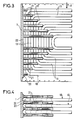
- FIG. 3 shows an end of a network 10 of tubes covered by a device according to the invention.
- This device 20 consists of tubes 21 parallel to each other and connected at their end to a support plate 22 fixed to the wall of the conduit 1, the various connections being made by any known means.
- each tube 21 is stopped at an elbow 12 in order to best reconstruct the pressure drop coefficient of the sections 11.
- FIG. 4 clearly shows the position of a device 20 between two networks 10.
- FIG. 5 shows a device 20 of triangular shape, consisting of a plate 25 of expanded metal, the plate having holes 26.
- FIG. 6 shows a device of rectangular shape made up of superimposed blades 23 and fixed at one of their ends to the support plate 22 by any known means. These blades are interconnected by vertical links 24 such as, for example blades or twisted son performing an assembly of the grating type.
Landscapes
- Engineering & Computer Science (AREA)
- General Engineering & Computer Science (AREA)
- Mechanical Engineering (AREA)
- Physics & Mathematics (AREA)
- Thermal Sciences (AREA)
- Heat-Exchange Devices With Radiators And Conduit Assemblies (AREA)
- Duct Arrangements (AREA)
- Sink And Installation For Waste Water (AREA)
- Details Of Indoor Wiring (AREA)
- Incineration Of Waste (AREA)
- Chimneys And Flues (AREA)
- Pipe Accessories (AREA)
- Protection Of Pipes Against Damage, Friction, And Corrosion (AREA)
- Physical Or Chemical Processes And Apparatus (AREA)
Priority Applications (1)
| Application Number | Priority Date | Filing Date | Title |
|---|---|---|---|
| AT85115670T ATE41509T1 (de) | 1985-08-14 | 1985-12-10 | Schutzvorrichtung fuer waermetauscher in einem rohr fuer mit feinen aschenteilchen beladenen rauch. |
Applications Claiming Priority (2)
| Application Number | Priority Date | Filing Date | Title |
|---|---|---|---|
| FR8512405 | 1985-08-14 | ||
| FR8512405A FR2586290B1 (fr) | 1985-08-14 | 1985-08-14 | Dispositif de protection d'echangeurs places dans un conduit de fumees chargees en fines particules de cendres |
Publications (2)
| Publication Number | Publication Date |
|---|---|
| EP0212003A1 true EP0212003A1 (de) | 1987-03-04 |
| EP0212003B1 EP0212003B1 (de) | 1989-03-15 |
Family
ID=9322245
Family Applications (1)
| Application Number | Title | Priority Date | Filing Date |
|---|---|---|---|
| EP85115670A Expired EP0212003B1 (de) | 1985-08-14 | 1985-12-10 | Schutzvorrichtung für Wärmetauscher in einem Rohr für mit feinen Aschenteilchen beladenen Rauch |
Country Status (10)
| Country | Link |
|---|---|
| US (1) | US4667733A (de) |
| EP (1) | EP0212003B1 (de) |
| AT (1) | ATE41509T1 (de) |
| BR (1) | BR8600692A (de) |
| DE (1) | DE3568861D1 (de) |
| FR (1) | FR2586290B1 (de) |
| GR (1) | GR853069B (de) |
| IN (1) | IN165805B (de) |
| YU (1) | YU45997B (de) |
| ZA (1) | ZA859702B (de) |
Families Citing this family (5)
| Publication number | Priority date | Publication date | Assignee | Title |
|---|---|---|---|---|
| US5094292A (en) * | 1991-06-10 | 1992-03-10 | Buckshaw Dennis J | Tube shield |
| US5154648A (en) * | 1991-08-23 | 1992-10-13 | Buckshaw Dennis J | Tube shield |
| US5474123A (en) * | 1994-04-19 | 1995-12-12 | Buckshaw; Dennis J. | Tube shield |
| CN104315497A (zh) * | 2014-10-27 | 2015-01-28 | 国网上海市电力公司 | 一种发电锅炉省煤器用防磨防爆装置 |
| FR3035955B1 (fr) * | 2015-05-06 | 2019-04-19 | Valeo Systemes Thermiques | Echangeur de chaleur comportant un dispositif de protection |
Citations (8)
| Publication number | Priority date | Publication date | Assignee | Title |
|---|---|---|---|---|
| GB633365A (de) * | 1900-01-01 | |||
| US2496540A (en) * | 1942-12-07 | 1950-02-07 | Thomas W Holmes | Heating system |
| GB653540A (en) * | 1947-07-02 | 1951-05-16 | Comb Eng Superheater Inc | Improvements in steam boilers and like heat exchangers |
| US2559069A (en) * | 1949-07-30 | 1951-07-03 | Standard Oil Co | Choke for abrasive fluids |
| US3568763A (en) * | 1969-02-26 | 1971-03-09 | Ingersoll Rand Co | Protective device for condenser tubes |
| FR2293674A1 (fr) * | 1974-12-06 | 1976-07-02 | Forissier Bouilhol Germain | Dispositif de recuperation de la chaleur evacuee dans les conduits de fumees par les appareils de chauffage notamment ceux agissant par l'intermediaire d'un fluide en circulation |
| US4007908A (en) * | 1975-05-09 | 1977-02-15 | Masoneilan International, Inc. | Process and device for attenuating noise caused by a valve during the expansion of a fluid |
| EP0123569A1 (de) * | 1983-03-15 | 1984-10-31 | Schlumberger Industries | Beruhigungsvorrichtung zum Regulieren des Geschwindigkeitsprofils eines strömenden Fluidums |
Family Cites Families (8)
| Publication number | Priority date | Publication date | Assignee | Title |
|---|---|---|---|---|
| DE301900C (de) * | ||||
| US2110024A (en) * | 1936-08-29 | 1938-03-01 | Gen Electric | Heat exchange unit |
| GB490727A (en) * | 1937-12-08 | 1938-08-19 | Tech Studien Ag | Tubular heat exchanger particularly suitable for heating air |
| US2303247A (en) * | 1941-04-22 | 1942-11-24 | Clifford Mfg Co | Heat exchange apparatus |
| US2847192A (en) * | 1955-09-12 | 1958-08-12 | Acme Ind Inc | Tube supporting and spacing structure for heat exchangers |
| US4422411A (en) * | 1981-05-29 | 1983-12-27 | International Coal Refining Company | Convective heater |
| JPS5813987A (ja) * | 1981-07-17 | 1983-01-26 | Sasakura Eng Co Ltd | 伝熱装置 |
| JPS60152892A (ja) * | 1984-01-18 | 1985-08-12 | エム・テ−・ウ−・モト−レン−・ウント・ツルビ−ネン−ウニオ−ン・ミユンヘン・ゲゼルシヤフト・ミツト・ベシユレンクテル・ハフツング | 熱交換器 |
-
1985
- 1985-08-14 FR FR8512405A patent/FR2586290B1/fr not_active Expired
- 1985-12-10 AT AT85115670T patent/ATE41509T1/de not_active IP Right Cessation
- 1985-12-10 EP EP85115670A patent/EP0212003B1/de not_active Expired
- 1985-12-10 DE DE8585115670T patent/DE3568861D1/de not_active Expired
- 1985-12-10 IN IN1041/DEL/85A patent/IN165805B/en unknown
- 1985-12-18 GR GR853069A patent/GR853069B/el not_active IP Right Cessation
- 1985-12-19 ZA ZA859702A patent/ZA859702B/xx unknown
- 1985-12-27 US US06/813,816 patent/US4667733A/en not_active Expired - Lifetime
-
1986
- 1986-01-23 YU YU8986A patent/YU45997B/sh unknown
- 1986-02-19 BR BR8600692A patent/BR8600692A/pt not_active IP Right Cessation
Patent Citations (8)
| Publication number | Priority date | Publication date | Assignee | Title |
|---|---|---|---|---|
| GB633365A (de) * | 1900-01-01 | |||
| US2496540A (en) * | 1942-12-07 | 1950-02-07 | Thomas W Holmes | Heating system |
| GB653540A (en) * | 1947-07-02 | 1951-05-16 | Comb Eng Superheater Inc | Improvements in steam boilers and like heat exchangers |
| US2559069A (en) * | 1949-07-30 | 1951-07-03 | Standard Oil Co | Choke for abrasive fluids |
| US3568763A (en) * | 1969-02-26 | 1971-03-09 | Ingersoll Rand Co | Protective device for condenser tubes |
| FR2293674A1 (fr) * | 1974-12-06 | 1976-07-02 | Forissier Bouilhol Germain | Dispositif de recuperation de la chaleur evacuee dans les conduits de fumees par les appareils de chauffage notamment ceux agissant par l'intermediaire d'un fluide en circulation |
| US4007908A (en) * | 1975-05-09 | 1977-02-15 | Masoneilan International, Inc. | Process and device for attenuating noise caused by a valve during the expansion of a fluid |
| EP0123569A1 (de) * | 1983-03-15 | 1984-10-31 | Schlumberger Industries | Beruhigungsvorrichtung zum Regulieren des Geschwindigkeitsprofils eines strömenden Fluidums |
Non-Patent Citations (1)
| Title |
|---|
| PATENTS ABSTRACTS OF JAPAN, vol. 7, no. 89 (M-207) [1234], 13 avril 1983; & JP - A - 58 13 987 (SASAKURA KIKAI SEISAKUSHO K.K.) 26-01-1983 * |
Also Published As
| Publication number | Publication date |
|---|---|
| US4667733A (en) | 1987-05-26 |
| IN165805B (de) | 1990-01-13 |
| BR8600692A (pt) | 1987-03-10 |
| DE3568861D1 (en) | 1989-04-20 |
| GR853069B (de) | 1986-04-21 |
| ZA859702B (en) | 1986-09-24 |
| ATE41509T1 (de) | 1989-04-15 |
| FR2586290B1 (fr) | 1989-02-03 |
| YU45997B (sh) | 1992-12-21 |
| FR2586290A1 (fr) | 1987-02-20 |
| EP0212003B1 (de) | 1989-03-15 |
| YU8986A (en) | 1989-08-31 |
Similar Documents
| Publication | Publication Date | Title |
|---|---|---|
| EP0212003B1 (de) | Schutzvorrichtung für Wärmetauscher in einem Rohr für mit feinen Aschenteilchen beladenen Rauch | |
| CH639187A5 (fr) | Chaudiere, notamment pour installation de chauffage. | |
| FR2474651A1 (fr) | Installation de rejet dans l'atmosphere ambiante d'un fluide gazeux sous pression a vitesse elevee | |
| EP1143153B1 (de) | Mit einer Vorrichtung zur Schwingungs- und Schockverringerung ausgestattes T-Stück in einer Gasrohranlage und mit einem derartigen T-Stück ausgestattete Rohranlage | |
| FR2703729A3 (fr) | Conduite d'échappement, en particulier pour véhicule à moteur. | |
| ATE44410T1 (de) | Heizanlage. | |
| RU2150047C1 (ru) | Водогрейный котел | |
| FR3041689B1 (fr) | Dispositif de suppression, partielle voire totale, d'un panache de fumees, ainsi qu'installation de rejet de fumees a l'atmosphere comprenant un tel dispositif | |
| US4372255A (en) | Five-smoke-flue type wet water box boiler | |
| FR2605714A1 (fr) | Chaudiere a air humide | |
| FR3077776B1 (fr) | Dispositif de chauffage electrique additionnel configure pour chauffer un flux d'air circulant dans un boitier d'installation de ventilation, de chauffage et/ou de climatisation de vehicule | |
| JPH05215302A (ja) | 伝熱管プロテクタ | |
| EP0088710A1 (de) | Einrichtung zur Wärmerückgewinnung aus den Verbrennungsgasen von Heizeinrichtungen | |
| JPH04101A (ja) | U型火炉ボイラ | |
| FR2646498A1 (fr) | Batterie de conditionnement d'air, destinee a assurer le chauffage ou le refroidissement d'un local | |
| EP0047010B1 (de) | Verbrennungseinrichtung, insbesondere für einen Dampfkessel | |
| US3263404A (en) | Spark arrester | |
| BE894088R (fr) | Dispositif de recuperation de chaleur sur les conduits de fumees de combustion | |
| FR2919532A1 (fr) | Systeme de protection de pieces chaudes d'un moteur | |
| EP0039870B1 (de) | Aufhängevorrichtung für Gasrohre | |
| SU1746115A1 (ru) | Конвективна поверхность нагрева | |
| EP0750448A1 (de) | Vorrichtung zur Aussenkühlung eines Plasmabrenners | |
| Roberts et al. | Combined cycle steam generator gas side fouling evaluation, phase 2[Final Report] | |
| FR2799535A1 (fr) | Chaudiere alimentant un circuit de chauffage et comprenant un echangeur-condenseur | |
| FR2699264A1 (fr) | Echangeur de chaleur muni d'un système anti-érosion. |
Legal Events
| Date | Code | Title | Description |
|---|---|---|---|
| PUAI | Public reference made under article 153(3) epc to a published international application that has entered the european phase |
Free format text: ORIGINAL CODE: 0009012 |
|
| AK | Designated contracting states |
Kind code of ref document: A1 Designated state(s): AT BE CH DE FR GB IT LI LU NL SE |
|
| 17P | Request for examination filed |
Effective date: 19870902 |
|
| 17Q | First examination report despatched |
Effective date: 19880105 |
|
| GRAA | (expected) grant |
Free format text: ORIGINAL CODE: 0009210 |
|
| AK | Designated contracting states |
Kind code of ref document: B1 Designated state(s): AT BE CH DE FR GB IT LI LU NL SE |
|
| REF | Corresponds to: |
Ref document number: 41509 Country of ref document: AT Date of ref document: 19890415 Kind code of ref document: T |
|
| GBT | Gb: translation of ep patent filed (gb section 77(6)(a)/1977) | ||
| REF | Corresponds to: |
Ref document number: 3568861 Country of ref document: DE Date of ref document: 19890420 |
|
| ITF | It: translation for a ep patent filed | ||
| PLBE | No opposition filed within time limit |
Free format text: ORIGINAL CODE: 0009261 |
|
| STAA | Information on the status of an ep patent application or granted ep patent |
Free format text: STATUS: NO OPPOSITION FILED WITHIN TIME LIMIT |
|
| 26N | No opposition filed | ||
| PGFP | Annual fee paid to national office [announced via postgrant information from national office to epo] |
Ref country code: LU Payment date: 19931015 Year of fee payment: 9 |
|
| EPTA | Lu: last paid annual fee | ||
| ITTA | It: last paid annual fee | ||
| PG25 | Lapsed in a contracting state [announced via postgrant information from national office to epo] |
Ref country code: LU Free format text: LAPSE BECAUSE OF NON-PAYMENT OF DUE FEES Effective date: 19941210 |
|
| EAL | Se: european patent in force in sweden |
Ref document number: 85115670.3 |
|
| PGFP | Annual fee paid to national office [announced via postgrant information from national office to epo] |
Ref country code: SE Payment date: 19981118 Year of fee payment: 14 Ref country code: DE Payment date: 19981118 Year of fee payment: 14 |
|
| PGFP | Annual fee paid to national office [announced via postgrant information from national office to epo] |
Ref country code: AT Payment date: 19981123 Year of fee payment: 14 |
|
| PGFP | Annual fee paid to national office [announced via postgrant information from national office to epo] |
Ref country code: BE Payment date: 19981209 Year of fee payment: 14 |
|
| PGFP | Annual fee paid to national office [announced via postgrant information from national office to epo] |
Ref country code: GB Payment date: 19991112 Year of fee payment: 15 |
|
| PGFP | Annual fee paid to national office [announced via postgrant information from national office to epo] |
Ref country code: NL Payment date: 19991122 Year of fee payment: 15 |
|
| PG25 | Lapsed in a contracting state [announced via postgrant information from national office to epo] |
Ref country code: AT Free format text: LAPSE BECAUSE OF NON-PAYMENT OF DUE FEES Effective date: 19991210 |
|
| PG25 | Lapsed in a contracting state [announced via postgrant information from national office to epo] |
Ref country code: SE Free format text: LAPSE BECAUSE OF NON-PAYMENT OF DUE FEES Effective date: 19991211 |
|
| PG25 | Lapsed in a contracting state [announced via postgrant information from national office to epo] |
Ref country code: BE Free format text: LAPSE BECAUSE OF NON-PAYMENT OF DUE FEES Effective date: 19991231 |
|
| BERE | Be: lapsed |
Owner name: STEIN INDUSTRIE Effective date: 19991231 |
|
| PG25 | Lapsed in a contracting state [announced via postgrant information from national office to epo] |
Ref country code: NL Free format text: LAPSE BECAUSE OF NON-PAYMENT OF DUE FEES Effective date: 20000701 |
|
| EUG | Se: european patent has lapsed |
Ref document number: 85115670.3 |
|
| NLV4 | Nl: lapsed or anulled due to non-payment of the annual fee |
Effective date: 20000701 |
|
| PG25 | Lapsed in a contracting state [announced via postgrant information from national office to epo] |
Ref country code: DE Free format text: LAPSE BECAUSE OF NON-PAYMENT OF DUE FEES Effective date: 20001003 |
|
| PGFP | Annual fee paid to national office [announced via postgrant information from national office to epo] |
Ref country code: CH Payment date: 20001120 Year of fee payment: 16 |
|
| PGFP | Annual fee paid to national office [announced via postgrant information from national office to epo] |
Ref country code: FR Payment date: 20001204 Year of fee payment: 16 |
|
| PG25 | Lapsed in a contracting state [announced via postgrant information from national office to epo] |
Ref country code: GB Free format text: LAPSE BECAUSE OF NON-PAYMENT OF DUE FEES Effective date: 20001210 |
|
| GBPC | Gb: european patent ceased through non-payment of renewal fee |
Effective date: 20001210 |
|
| PG25 | Lapsed in a contracting state [announced via postgrant information from national office to epo] |
Ref country code: LI Free format text: LAPSE BECAUSE OF NON-PAYMENT OF DUE FEES Effective date: 20011231 Ref country code: CH Free format text: LAPSE BECAUSE OF NON-PAYMENT OF DUE FEES Effective date: 20011231 |
|
| REG | Reference to a national code |
Ref country code: CH Ref legal event code: PL |
|
| PG25 | Lapsed in a contracting state [announced via postgrant information from national office to epo] |
Ref country code: FR Free format text: LAPSE BECAUSE OF NON-PAYMENT OF DUE FEES Effective date: 20020830 |
|
| REG | Reference to a national code |
Ref country code: FR Ref legal event code: ST |